1
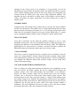
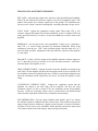
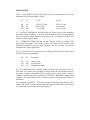
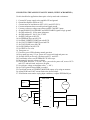
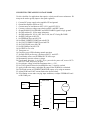
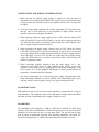
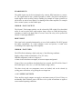
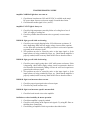
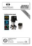
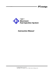
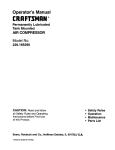
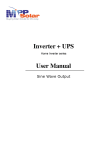
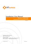
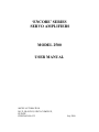
‘ENCORE’ SERIES
SERVO AMPLIFIERS
MODEL 2500
USER MANUAL
ARCEE AUTOMATION
NO.32, BLOCK II, SIDCO COMPLEX,
GUINDY,
CHENNAI 600 032.
July 2000
INTRODUCTION
The ‘Encore’ Series amplifiers are second generation products designed for low cost
and high performance. They are designed for edgewise mounting and can operate
from power supplies ranging from 24V to 150V DC.
A wide range of inductive loads can be driven by the amplifiers. All models feature
fully differential inputs for the control, or reference, voltage. Enable inputs for the
control of outputs, and status signal and current monitor output are provided to ease
system interfacing.
The 22 KHz switching frequency eliminates audible noise from the motor windings,
and fast rise and fall times give high efficiency.
The amplifiers are protected against over temperature, over and under voltage, and
short circuits between outputs, and from outputs to ground.
They are typically used as voltage to current converters. A +/- 10V signal will drive
the amplifier’s peak rated current to the load in the ‘flat gain’ mode. If a tachometer is
used, the amplifier is still operated as a voltage to current converter, but DIP switch
settings are changed to increase the gain of the servo amplifier.
Voltage mode operation with IR compensation is also supported and is switch
selectable.
Loads driven are normally motors, but magnet coils, inductors or other non-motor
loads can also be driven using appropriate settings.
THEORY OF OPERATION
AC voltage from the transformer is rectified and filtered to provide the DC bus
voltage for the power stage. The power stage is a full bridge formed by power
MOSFETs, and is capable of allowing the motor to accelerate or brake in either
direction. The MOSFETs use separate floating power supplies for their gate drives,
which allow the drive to operate without any restriction on the duty cycle.
The innermost control loop in the drive is a current control loop, the heart of which is
a resistive feed-back element and the PWM control circuit. In the torque mode, the
input signal is fed directly to the current loop and so the motor current is made equal
to the input signal. The PWM circuit switches each leg of the bridge alternately to the
bus voltage and to ground, to maintain the motor current at the desired value.
In the velocity mode, an outer loop is formed by comparing the tachometer’s output
voltage and the input signal. Thus, the motor’s speed will equal the input signal. If the
motor’s speed varies due to load or voltage variations, the drive adjusts the motor
current till the preset speed is again achieved. In the velocity mode, the tach,
proportional , integral gains and integration time constant are all variable to allow
tuning of the drive to varying load and speed conditions.
SALIENT FEATURES
MOSFET DRIVE FOR HIGH EFFICIENCY
Rugged power MOSFETs are used in the power stage. These have lower losses than
comparable bipolar transistors, resulting in higher efficiency and also improved
reliability due to lower temperatures. Also, MOSFETs have peak current ratings of
approximately 10 times the average current, which makes them totally immune to
spikes and surges.
ELECTRONIC SHORT CIRCUIT PROTECTION
An electronic circuit monitors the total supply current, and shuts off the voltage drive
to each MOSFET if a predetermined limit is exceeded. This protects the output stage
from direct shorts to either power rail as well as direct shorts across the armature
terminals.
DIFFERENTIAL COMMAND INPUT
This provides high noise immunity, and is essential for proper operation in electrically
noisy environments, and to eliminate switching noise picked up by the tach from
integrated tach-motor packages.
AVERAGE CURRENT LIMITING FOR OVERLOAD PROTECTION
When the average current setting of the drive is exceeded, an analog timer starts.
When the preset time limit is exceeded, the drive current is clamped to the set average
value. This logic completely protects the motor from any overload damage.
VOLTAGE AND TEPMERATURE PROTECTION
The drive monitors logic and power supply voltages, as well as driver heat sink
temperatures and shuts down the drive in the event the preset limits are exceeded.
FAULT OUTPUT
An open collector signal is available as an output from the drive, which can be set to
activate either when the drive is in a normal state, or shut down due to a fault. This
feature allows the signal to be used for driving a relay to be used for controlling a
power fail brake mounted on the motor shaft, if required.
INTEGRATED HEATSINK AND COOLING FAN
An integrated heat sink with cooling fan is provided for reliable operation at high
ambient temperatures. The cooling fan requires an external 220V AC supply.
TECHNICAL SPECIFICATIONS : MODEL ENCORE 2500
Typical specs at 25 degrees C, supply voltage = 150V DC, load = 0.25 mH + 2 ohms.
SUPPLY VOLTAGE
Minimum supply voltage
Typical operating supply voltage
Maximum operating supply voltage
Typical Aux. Supply for cooling fan
:
:
:
:
24 V DC
150 V DC
155V DC
220V AC 50Hz 0.2 Amps
OUTPUT POWER
Peak power output @ 30A, 150V ( 2 sec unipolar / 4 sec bipolar) :
Continuous power output @ 15A, 150V
:
4500 W
2250 W
OUTPUT CURRENT
Peak output current @ Vout = +/-150V ( 2 sec unipolar / 4 sec bipolar)
Continuous current @ 50 degrees C ambient
: +/-30A
: +/-15A
OUTPUT VOLTAGE
Vout = Vsupply – 0.12 * Iout
LOAD INDUCTANCE
Switch selectable in three ranges, 0.13 to 20 mH @ 75V, 0.25 to 40 mH @ 150V
SMALL SIGNAL BANDWIDTH
-3dB @ 3KHz
22 KHz
SWITCHING FREQUENCY
INPUT CHARACTERISTICS
Reference input
Max. input voltage
Tachometer
Max. tachometer input
Input amplifier drift
Differential, 90 K ohm min. between inputs
+/-10 volts
Single ended, 21 K ohms
+/-30 volts
0.05% per degree C
OVERCURRENT TIME LIMITS
The continuous current limit trimpot setting will affect the time limit at peak output
currents as follows :
Continuous current setting
Time limit, Unidirectional change
Time limit, Bidirectional change
GAINS
Input differential amplifier
Servo preamplifier
Power amplifier stage
Current monitor
15A
2
4
10A
1.5
3
5A
1
2
sec
sec
1.0
Adjustable
2 A/V
5.0 A/V
ADJUSTABLE SETTINGS
Trimpots : Peak current, Continuous current, Reference gain, Feedback, Tachometer
gain, Balance, IR compensation.
DIP switches : Load inductance, Voltage feedback, Alternate compensation, Low
gain, Flat gain, IR compensation, Normal polarity.
LED INDICATOR
Normal / Fault
LOGIC INPUTS
Enable Pos Enable Neg Enable Reset -
Red / Green ( Bicolour)
74HC levels, active low.
Low enables amplifier
Low enables + output
Low enables – output
Low resets fault
LOGIC OUTPUTS
Normal: Open drain MOSFET output, 100 mA / 50V
S8 open : Low when normal, High on fault condition
S8 closed : High when normal, Low on fault condition
Overcurrent
CMOS 5V output
AUXILIARY OUTPUTS
+/- 12 V
PROTECTION FEATURES
Current v/s. time limiting
Heatsink temp. limit
Over-voltage shutdown
Undervoltage shutdown
Output short circuit
10 mA max.
2 secs max @ +/-30A
83 degrees C
155V
22 V
Output-output, output-Ground
THERMAL REQUIREMENTS
Maximum ambient temperature
Maximum power dissipation
50 degrees C
50W @ +/- 15 Amps
MECHANICAL
Size without heatsink and cooling fan
Size including heatsink and cooling fan
Weight
40 x 230 x 155 mm
103 x 230 x 155 mm
1.5 Kgs
CONNECTORS : SIGNALS AND PINOUTS
Motor and power connections are made via a four terminal screw connector ( P2 ).
Signal connections are made via a 15 pin 0.1” pitch connector ( P1 ).
4 PIN POWER CONNECTOR P2
PIN 1 : MOTOR OUT +, positive output
PIN 2 : MOTOR OUT -, negative output
PIN 3 : + HV RETURN (GND)and chassis ground
PIN 4 : +HV, the high voltage DC power input.
15 PIN SIGNAL CONNECTOR P1
PIN 1: +12V OUT, 10 mA MAX.
PIN 2 : ENABLE-, ACTIVE LOW CMOS INPUT.
PIN 3 : NEG ENABLE-, ACTIVE LOW CMOS INPUT.
PIN 4 : POS ENABLE-, ACTIVE LOW CMOS INPUT.
PIN 5 : RESET-, ACTIVE LOW CMOS INPUT.
PIN 6 : NORMAL / FAULT OPEN COLLECTOR OUTPUT.
PIN 7 : OVERCURRENT CMOS OUTPUT.
PIN 8 : CURRENT MONITOR OUTPUT.
PIN 9 : AUX INPUT.
PIN 10 : SIGNAL GROUND.
PIN 11 : -REF IN ( DIFFERENTIAL INPUT ).
PIN 12 : + REF IN ( DIFFERENTIAL INPUT ).
PIN 13 : SIGNAL GROUND.
PIN 14 : TACH INPUT.
PIN 15 : -12V OUT, 10 mA MAX.
GETTING STARTED
To install the amplifier you will require a control, or reference, voltage, a power
supply, and a load. The reference voltage can be as simple as a potentiometer, or as
complex as a digital control system. First you must determine the mode of operation,
and the connect the amplifier to power supply, load and control system. Once
installed, you will next power up and check that the motor, tachometer and control
signal polarities are correct. The final operation is tuning, the process of adjusting
amplifier gain, control system parameters, etc. to achieve the desired performance of
the system.
OPERATING MODES
A mode is simply the way that the amplifier is used. Because the amplifier is one of
the several components comprising a system, the operating mode frequently depends
on the other components in the system. A tachometer is the most important option in
determining the operating mode. If you use a tachometer, the amplifier will be
operating in the velocity mode. If no tachometer is used, typically you will be
operating in the current mode. In both these modes, the amplifier operates as a current
source, and the difference between them is in the setup of the servo preamplifier, the
section between the PWM power stage and the input differential amplifier. The
amplifier can also be operated as a voltage source. In this fashion, a given reference
voltage will produce an output voltage that will remain constant over a range of
output currents.
CURRENT MODE
Commonly used with microprocessor controls that use encoders for motion feedback
and don’t use tachometers. The amplifier acts as a wide bandwidth current source that
puts out its peak current rating in response to a +/-10V reference voltage input. In this
mode the servo preamplifier operates at low gain, and the PWM stage as a current
source, changing the output voltage in order to maintain a constant output current.
VELOCITY MODE
Used with a tachometer. In this mode the amplifier continues to act as a wide
bandwidth current source. The servo preamplifier operates at high gain, because it is
amplifying the difference of the tachometer and the reference signal. The PWM stage
again operates as a current source to accelerate / decelerate the motor to produce an
RPM which makes the tachometer signal equal to the reference signal.
VOLTAGE MODE
This mode is used less frequently because it produces lower performance from the
motor. As a voltage amplifier, an input voltage will produce an output voltage, which
will remain relatively constant over a range of output currents. The servo preamplifier
now amplifies the difference between the reference voltage, and the scaled down
sample of the output voltage.
VOLTAGE MODE WITH IR COMPENSATION
This is a variation of voltage mode operation in which the servo preamplifier sees not
only the reference and output voltages, but also the output current. Because the
armature voltage ( back emf, which produces the motor RPM ) is the difference
between the motor terminal voltage and the internal drop across the armature
resistance, the it will decrease when greater loads produce greater currents. This
current produces an “IR” drop ( current x resistance = voltage ) which subtracts from
the terminal voltage of the amplifier. IR compensation mode increases the amplifier
output when the load current increases. When adjusted correctly, the increase will just
compensate the IR drop and the motor speed will remain constant without a
tachometer. The actual regulation will not be as good as with a tach, but is simpler
and cheaper than using a tach, and is adequate for many situations.
FRONT PANEL ADJUSTMENT TRIMPOTS
REF. GAIN : Attenuates the output of the reference signal gain differential amplifier.
Fully CW will send the full reference signal to the servo preamplifier stage. CCW
rotation will result in less reference signal sent to the preamp. This adjustment acts
like an overall ‘volume’ control for the amplifier, controlling the amps-out per volt-in.
TACH. GAIN : Adjusts the tachometer scaling signal. When fully CW, a 10V
reference signal will demand 10V from the tachometer. As this is adjusted CCW, the
motor speed will increase. Use this to set the basic RPM-out to volts-in ratio of the
amplifier.
FEEDBACK : Sets the gain of the servo preamplifier. Usually set to a minimum (
fully CW ) in current mode operation for maximum bandwidth. When using
tachometers, turn this pot CCW until oscillation begins, and then back off 1 or 2
turns for stable operation. Adjustment of this pot affects the response of the amplifier
to a step input.
BALANCE : Used to ‘null’ the output of the amplifier when the reference inputs are
at 0 V. adjust the pot for zero current, or for zero volts between motor + and motorwhen the input to the amplifier is zero.
PEAK CURRENT LIMIT : Controls the peak current the amplifier can output to the
load. Fully CW the amplifier will drive the rated peak current. As this is turned CCW,
the maximum current will gradually decrease. Useful for protecting mechanical parts
when the maximum current required by the load is less than the amplifier’s peak
rating.
CONTINUOUS CURRENT LIMIT : Controls the continuous current that the
amplifier can output to the load. Fully CW the amplifier will drive the rated
continuous current. As this is turned CCW, the continuous current will gradually
decrease. Useful for protecting motors such as printed-circuit and basket-wound
motors that have high peak current but low continuous current ratings.
IR COMPENSATION : Used in voltage feedback mode with S3 and S7 on. Adjusts
the amount of positive feedback from the current circuit. This feedback increases the
output voltage when the load draws a higher current. Because it is positive feedback,
too much of it can cause severe oscillation. When adjusted correctly the motor speed
will remain constant as the load changes, without using a tachometer.
DIP SWITCHES
S1,S2 : LOAD INDUCTANCE SELECTOR. Set these two switches based on the
inductance of the load and supply voltage.
S1
S2
at 75V
at 150V
On
Off
Off
On
On
Off
0.13 to 0.75 mH
0.8 to 5 mH
5.1 to 20 mH
0.25 to 1.5 mH
1.6 to 10 mH
10.1 to 40 mH
S3 : VOLTAGE FEEDBACK. No effect when off. When on this switch substitutes
the output voltage divided by 25 in place of the tachometer, converting the amplifier
from a current to a voltage amplifier. If the gain of 25 is too high, use the Ref. Gain
trimpot to reduce the gain further.
S4 : ALTERNATE COMP. Typically the Ref. Gain pot will be set to fully CCW
when using this feature. This switch connects the output of the reference gain
differential amplifier to the Aux. Input internally. The servo preamp. Can then be
customized for special applications.
S5, S6 : GAIN SETTING. Set the switches according to the chart below. They adjust
the gain of the servo preamplifier.
S5
S6
Gain mode
On
Off
Off
On
Off
On
Current mode
Velocity mode
Medium Gain mode
S7 : IR COMPENSATION . Enables feedback from the current monitor when on.
This mode is an option when operating in voltage mode. IR compensation increases
the output voltage to compensate for the voltage drop across the motor’s armature
resistance. Normally this drop would decrease the motor’s RPM under cahnging load
conditions. IR compensation permits a relatively constant velocity operation without a
tachometer.
S8 : NORMAL POLARITY . This switch changes the polarity of the Normal / Fault
output. With S8 off, a normal condition turns the output On. When S8 is On, the logic
is reversed and a fault condition turns the output On.
CONNECTING THE AMP IN CURRENT MODE ( NO TACHOMETER )
Use this checklist for applications that don’t require a tachometer. These include
control systems that get their feedback from an encoder, as well as non-motor
applications that require a set current from the amplifier in response to the control
voltage at the input.
1. Connect DC power supply to the amplifier HV and ground.
2. Ground the amplifier chassis at P2-3.
3. Connect motor or load between OUT+(P2-1) and OUT-(P2-2).
4. Connect a reference voltage source between REF+ and REF- inputs.
5. Ground ENABLE, POS ENABLE and NEG ENABLE signals to logic ground.
6. Set DIP switches S1, S2 for motor inductance.
7. Set DIP switches S3, S4, S7 OFF and set S5, S6 ON.
8. Set REF GAIN pot to full CW.
9. Set FEEDBACK pot to full CCW.
10. Set PEAK CURRENT LIMIT pot to half CW.
11. Set CONT CURRENT LIMIT pot to half CW.
12. Set TACH GAIN pot to full CW.
13. Set IR COMP pot to full CCW.
14. Set VREF to zero volts.
15. Turn power on.
16. Check for green LED indicating normal operation.
17. Set BALANCE pot for zero volts between OUT+ and OUT -.
18. Momentarily increase reference voltage.
19. Check motor direction : is it OK ? If yes, proceed else power off, reverse OUT+
and OUT-, and power on again.
20. Set reference voltage to maximum value ( +/-10V ).
21. Check load current at CURRENT MONITOR output, or by using an ammeter in
series with the load.
22. Adjust PEAK and CONT current limit to the desired values.
AMPLIFIER 1
12
REF +,-
11
2
MOTOR
2
3
4
10
P1
4
3
P2
24-150V DC
CONNECTING THE AMP IN VELOCITY MODE ( WITH TACHOMETER )
Use this checklist for applications that require velocity mode and a tachometer.
1. Connect DC power supply to the amplifier HV and ground.
2. Ground the amplifier chassis at P2-3.
3. Connect motor or load between OUT+(P2-1) and OUT-(P2-2).
4. Connect tachometer between tach input and signal ground.
5. Connect a reference voltage source between REF+ and REF- inputs.
6. Ground ENABLE, POS ENABLE and NEG ENABLE signals to logic ground.
7. Set DIP switches S1, S2 for motor inductance.
8. Set DIP switches S3, S4, S5, S6, S7 OFF.
9. Set REF GAIN pot to full CW.
10. Set FEEDBACK pot to full CCW.
11. Set PEAK CURRENT LIMIT pot to half CW.
12. Set CONT CURRENT LIMIT pot to half CW.
13. Set TACH GAIN pot to full CW.
14. Set IR COMP pot to full CCW.
15. Set VREF to zero volts.
16. Turn power on.
17. Check for green LED indicating normal operation.
18. Does motor run away ? If yes, power off. reverse tach leads and power on.
19. Set BALANCE pot for zero volts between OUT+ and OUT -.
20. If oscillation occurs, turn FEEDBACK CW till it stops.
21. Momentarily increase reference voltage.
22. Check motor direction : is it OK ? If yes, proceed else power off, reverse OUT+
and OUT- and tach leads, and power on again.
23. Set reference voltage to maximum value ( +/-10V ).
24. Set TACH gain till desired RPM is reached.
25. Check load current at CURRENT MONITOR output, or by using an ammeter.
26. Adjust PEAK and CONT current limit to the desired values.
27. If oscillation occurs under varying input conditions, re-adjust FEEDBACK pot.
AMPLIFIER 1
12
REF +,-
11
MOTOR
14
13
2
2
TACH
3
4
4
3
10
P1
P2
24-150V DC
CONNECTING THE AMP IN VOLTAGE MODE
Use this checklist for applications that require velocity mode but no tachometer. IR
comp can be used to greatly improve the speed regulation.
1. Connect DC power supply to the amplifier HV and ground.
2. Ground the amplifier chassis at P2-3.
3. Connect motor or load between OUT+(P2-1) and OUT-(P2-2).
4. Connect a reference voltage source between REF+ and REF- inputs.
5. Ground ENABLE, POS ENABLE and NEG ENABLE signals to logic ground.
6. Set DIP switches S1, S2 for motor inductance.
7. Set DIP switches S4, S5, S6, OFF. Set S3 ON, also S7 if using IR COMP.
8. Set REF GAIN pot to full CW.
9. Set FEEDBACK pot to full CCW.
10. Set PEAK CURRENT LIMIT pot to half CW.
11. Set CONT CURRENT LIMIT pot to half CW.
12. Set TACH GAIN pot to full CW.
13. Set IR COMP pot to full CCW.
14. Set VREF to zero volts.
15. Turn power on.
16. Check for green LED indicating normal operation.
17. Set BALANCE pot for zero volts between OUT+ and OUT -.
18. If oscillation occurs, turn FEEDBACK CW till it stops.
19. Momentarily increase reference voltage.
20. Check motor direction : is it OK ? If yes, proceed else power off, reverse OUT+
and OUT- leads, and power on again.
21. Set reference voltage to half the maximum value ( +/-5V ).
22. Set TACH gain till desired no load RPM for max / 2 signal is reached.
23. Apply a load to the motor, and adjust IR comp till the old RPM is re-obtained.
24. Check load current at CURRENT MONITOR output, or by using an ammeter.
25. Adjust PEAK and CONT current limit to the desired values.
26. If oscillation occurs under varying input conditions, re-adjust FEEDBACK and /
or IR COMP pots.
AMPLIFIER 1
12
REF +,-
11
MOTOR
2
2
3
4
4
3
10
P1
P2
24-150V DC
POWER SUPPLY AND WIRING CONSIDERATIONS
1. Make sure that the applied supply voltage is adequate to drive the motor at
maximum current and maximum RPM. This should equal the maximum motor
voltage on load, plus saturation losses in the amplifier and an extra 5 to 10 percent
for ripple.
2. Under low input supply conditions, the voltage requirement of (1) may not be met,
and this may be seen effectively as poor regulation at high speeds, since the
amplifier may not have adequate ‘headroom’.
3. When operating with low voltage supplies close to 24V, check the Normal LED
while accelerating. If it goes off occasionally, it may be due to supply going below
22V while the motor draws accelerating current. In this case, filter capacitor value
and / or supply voltage should be increased.
4. When operating with higher supply voltages close to 150V, check the Normal
LED while decelerating. If it goes off occasionally, it may be due to the fact that
the energy pumped back from the inertial load back to the power supply capacitor
causes the supply to exceed 155V. In this case, reduce the power supply voltage,
reduce the deceleration rate or install a regenerative brake. Contact factory for
details of regenerative brake.
5. When connecting multiple amplifiers from the same supply, use a ‘star’
connection with supply wires to each amplifier going directly to the filter
capacitor. Don’t ‘daisy chain’ by looping power leads from one amplifier to the
next. Connect P2-3 of each amplifier individually to chassis ground, and do not
ground the – terminal of the filter capacitor.
6. Use wires of appropriate size for connecting power supply and main motor leads.
Keep connecting conductors as short as possible, and avoid bundling these wires
with any sensitive control signals, as they carry large switching currents.
LOAD INDUCTANCE
DIP switches S1 and S2 can be used to set the amplifier to compensate for a range of
load inductances. The inductance range varies with applied voltage, and this should be
taken into account if significantly lower supply voltages are used.
BANDWIDTH
The bandwidth of the amplifier is –3dB at 3 KHz and is defined for small signal
operation. The effect of bandwidth is to limit the freqeuncy of a sine wave that can be
amplified, or to limit the rise time of a step input signal. The type of load will also
have an effect on bandwidth, especially with increasing inductance. The factor V/L
will be the limiting factor, as it defines the maximum rate of change of current.
ENABLE INPUTS
The enable inputs may be driven through relay contacts, NPN transistors or sensors,
etc. The signals must be low ( pulled to ground ) to enable. The positive and negative
enable signals can be used for selective enabling, for example in a linear system to cut
off the drive at end-of-travel limits. For shutting off the entire amplifier, for example
from a control system, use the Enable input.
NORMAL / FAULT OUTPUT
The Normal / Fault output polarity can be selected by DIP switch S8 as described
earlier. It can be used to drive opto-couplers, lamps, relays etc. While driving relays,
remember to install a fly-back diode in reverse across the relay coil to protect the
Normal / Fault output MOSFET.
RESET INPUT
This signal can be grounded momentarily to reset a fault condition. DO NOT ground
this input continuously. If a fault condition occurs and persists, it could cause
overheating of the output stage of the amplifier.
NORMAL / FAULT LED
The LED is Red, indicating a fault, under any of the following conditions :
Supply voltage outside normal limits ( 22 to 155 volts ).
Heatsink temperature is above 83 degrees C.
A short circuit exists between outputs, or between outputs and ground.
If none of the error conditions described above has occurred, the LED will be Green if
the Enable input is low ( true ), or off if the Enable is high ( false ).
The short circuit and over temperature errors are latched, and can be cleared by
cycling power off and on, or by pulsing the reset input low.
+/- 12 V SUPPLY OUTPUTS
These auxiliary supply outputs can supply a maximum current of 10 mA. If they are
accidentally short circuited, power will have to be cycled off and then on again to
restore normal operating conditions.
TROUBLESHOOTING GUIDE
Amplifier NORMAL light does not come on.
1. Check that at least between 24V and 150V DC is available at the amp’s
DC power input. Increase or decrease supply if outside these limits.
2. Check that the enable signal is low ( active ).
Amplifier FAULT light is always on.
1. Check for high temperature caused by failure of cooling fan or loss of
220V AC supply to cooling fan.
2. Check for possible short from motor wires to ground, or across motor
wires.
NORMAL light goes off while accelerating.
1. Check for power supply dipping below 24V while motor accelerates. If
this is happening, either increase supply voltage, increase filter capacitor
or slow down the acceleration by adding a resistor in series and a capacitor
to ground on the reference signal.
2. This problem can also be caused by noise on the input signal, or if the
input reference is being switched by relays, etc. Check that the amplifier is
properly earthed, and if necessary install an RC filter as described above.
NORMAL light goes off while decelerating.
1. Check for power supply going above 160V while motor accelerates. If this
is happening, either reduce supply voltage, install a regenerative brake or
slow down the deceleration by adding a resistor in series and a capacitor to
ground on the reference signal.
2. This problem can also be caused by noise on the input signal, or if the
input reference is being switched by relays, etc. Check that the amplifier is
properly earthed, and if necessary install an RC filter as described above.
NORMAL light is on but motor does not run.
1. Check for proper input signal at the reference input.
2. Check for any break in motor wires.
NORMAL light is on but motor speed is uncontrolled.
1. Check for break in tach wires to the amplifier.
Oscillation or other instability in motor operation.
1. Check that amplifier is properly earthed.
2. Check for noise pickup on the input or tach signals. Try using RC filters or
shielding these connections.
3. Check tuning of amplifier. Refer to procedures described earlier.
FEEDBACK
BALANCE
PEAK I
CONT I
IR COMP
TACH
REF GAIN
S1
S8
FLT/NORM
P1-15
P1-1
OUT +
OUT GND
HV
E NCO RE
PWM SERVO AMPLIFIER