1
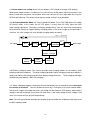
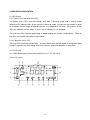
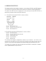
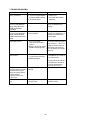
Inverter + UPS
Home Inverter series
User Manual
Sine Wave Output
IMPORTANT SAFETY INSTRUCTIONS
● When replacing the batteries, use the same number and the same type of batteries.
● Do not dispose of batteries in a fire; the battery may explode.
● Do not open or mutilate the battery or batteries, released electrolyte is harmful to the skin and
eyes.
● A battery can present a risk of electric shock and high short circuit current. The following
precaution should be observed when working on batteries.
* Remove watches, rings or other metal objects.
* Use tools with insulated handles.
● To prevent an overbalance of this unit, with the installation the additional stabilizer are to mount at
the bottom side.
● This unit should be installed by service personnel.
● The equipment can be operated by any individuals with no previous experience.
● “The socket-outlet shall be installed near the equipment and easily accessible.”
● “With the installation of this equipment it should be prevented, that the sum of the leakage current
of the inverter at the connected consumer does not exceed 3.5mA.”
● Attention: hazardous through electric shock. Also, with disconnection of this unit from the main,
hazardous voltage still may be accessible through supply of battery.
● The battery supply should be therefore disconnected in the plus and minus pole through or from
the outer enclosure accessible battery fuses when maintenance or service work inside the inverter
is considered.
● The lead acid battery may cause chemical hazard.
● The battery presents a risk of electric shock and energy hazard.
● Batteries will be disposed by the manufacturer or importer.
Customers need to send them back
with no charge for disposal.
SAVE THESE INSTRUCTION. This manual is important instructions that you should follow
during installation and maintenance of the Inverter and batteries. Please read all instructions
before operating the equipment and save this manual for future reference.
1
CAUTION:
● The inverter connection instructions and operation described in the manual must be followed in the
indicated order.
● The inverter must be connected to a near by wall outlet that is easily accessible.
The inverter can
be disconnected from the AC-power source by removing the power cord.
● Check that the indications on the rating plate correspond to your AC-power system and to the actual
electrical consumption of all the equipment to be connected to the inverter.
● Never install the inverter near liquids or in an excessively damp environment.
● Never let a foreign body penetrate inside the inverter.
● Never block the ventilation grates of the inverter.
● Never expose the inverter to direct sunlight or source of heat.
● If the inverter must be stored prior to installation, storage must be in a dry place.
● The admissible storage temperature range is -15℃ to +55℃.
● All handling operations will require at least two people (unpacking, installation in rack systems).
● Once installed and connected to the AC power source for the first time, the battery will start to
charge. Full charging to obtain the rated battery backup time requires at least 8 hours.
● Before and after the installation, in case of any doubt, do Not hesitate to contact our service
department.
2
Special Symbols
The following are examples of symbols used on the unit to alert you the important information.
RISK OF ELECTRIC SHOCK Indicates that a risk of electric shock is present and the associated warning
should be observed
CAUTION; REFER TO OPERATOR’S MANUAL Refer to your operator’s manual for additional information, such as important
operating and maintenance.
SAFETY EARTHING TERMINAL Indicates the primary safety ground.
RJ-45 RECEPTACLE For 230V units only, this receptacle provides network interface connections.
Do not plug telephone or telecommunications equipment into this receptacle.
This symbol indicates that you should not discard the inverter or the inverter
batteries in the trash. The inverter & the sealed, lead-acid batteries must
be recycled.
3
TABLE of CONTENTS
1.
2.
Over view and Features ---------------------------------------------------------- Page 5
Presentation -------------------------------------------------------------------------- Page 6
2.1
LED display models
2.2
LCD display models
2.3
Rear Panels --------------------------------------------------------------------------- Page 7
3.
Installation ---------------------------------------------------------------------------- Page 8
4.
Operation ------------------------------------------------------------------------------ Page 9
5.
Indication and Control ------------------------------------------------------------ Page 12
5.1
LED Display
5.2
LCD Display
5.3
Audible alarm ------------------------------------------------------------------------- Page 14
5.4
Auto self-test Function
5.5
Remote Control ----------------------------------------------------------------------- Page 15
5.6
Reset the Inverter
5.7
DIP Switch Setting
6.
Communication interface ------------------------------------------------------- Page 16
7.
Trouble shooting ------------------------------------------------------------------- Page 17
8.
Specifications ----------------------------------------------------------------------- Page 18
4
1. OVER VIEW AND FEATURES
The series Inverter is advanced & friendly designed with pure sine-wave output to your equipment;
besides a big charger up to 35A (depending on model), the inverter, unlike the traditional one, also
provides a very short transference when blackouts happen; thus, you may apply it as an UPS, too.
Further, it is also made with Wide Range AVR, output ±10% with input range as large as 140V ~
310V in the rated 230V area; or 70V ~ 155V in the 115V area. With the wide AVR, you won't need
to use the valuable battery energy when in a brownout. The series provides efficiency over 97%
under normal power condition, and 86% under inverter mode. Two charge modes, quick and trickle
charge, are applied in the big charger, and so as to maintain the batteries in the best condition.
With outstanding performance & reliability, the unique benefits of the inverter include the following:
* Pure sine wave output.
* Microprocessor based design with true Line-Interactive structure, DC/AC Isolation.
* Remaining Estimated Backup Time indication (EBT system on LCD version).
* Wide input range 140V~310V for 230V area; and 70V~155V for 115V area.
* Adjustable charging voltage & voltage-transfer points.
* Smart battery management with intelligent double stages of charging control.
*
*
*
*
Adjustable charging current by DIP switch for different battery.
Real time auto-detection for battery condition.
Automatic restart of load after Inverter shutdown.
Smart AVR function (Two buck / boost modes).
* Generator compatible & Cold-start capable.
* “Green Power” design with auto on/off function & adjustable level.
* Network manageable (SNMP optional).
* Optional RS-232/USB interface for communication, compatible with all major O.S., including
Windows, Linux, SCO UNIX, & DOS.
* Protection for overload, short circuit, & over heat; also with thermal control cooling fan.
* Support Solar panel input for charging (Optional)
5
2. PRESENTATION
2.1 LED display models
There are many types of LED display for different models; however, they all use the same control
method, the following is an example of it:
1
LEDs of battery voltage level and load level.
2
LED of operation status.
3
Control button.
2.2 LCD display models
The following is one example of LCD display; the location of control buttons could be different for
some models; however, the functions of buttons are the same.
1
Main control button.
2
LCD screen.
3
Selection button for mode & value.
6
2.3 Rear Panels — Tower type
Description of Rear panel in Tower
1. Circuit Breaker for Input.
2. Input Terminal.
3. Output Terminal and / or Outlet(s) (NEMA
or IEC).
4. RS-232 Interface port (for application with
optional Monitoring software)
5. DIP Switch.
6. RJ-45 Interface for Remote LCD display
(Optional).
7. Battery connector.
8. Auto-bypass On/Off Switch (Turn on switch
to enable Auto-bypass function).
9. Bypass LED Indicator.
2.3 Rear Panels — Wall-mount type
1600 ~ 4000
800 / 1200
1 Input circuit breaker
○
7 Battery connector
○
2 Input terminal of city power
○
8 Connector for solar panel (Optional)
○
3 Output circuit breaker for outlets
○
9 Internal SNMP Slot or USB (Optional)
○
4 Output terminal & Outlets (IEC or NEMA)
○
10 Auto-bypass On/Off Switch (Turn on switch
○
5 RS-232 Interface port
○
to enable Auto-bypass function)
6 DIP Switch
○
11 Bypass LED Indicator
○
7
3. INSTALLATION
3.1 Inspecting the packing carton for damage that may have occurred while in transit. Immediately
notify the carrier and place of purchase if any damage is found. Retain the package for future use.
3.2 Connect the AC power only to a grounded shockproof wiring system to avoid electric shocks
resulted from current leakage.
Keep wire length as short as possible to minimize voltage loss.
The installation must be performed by qualified personnel.
Recommended AC wire size:
Capacity \ Input voltage
110/115/120Vac
220/230/240Vac
800VA ~ 1.6KVA
AWG14
AWG16
2.4KVA
AWG12
AWG14
3.2KVA
AWG10
AWG12
4KVA
N/A
AWG12
3.3 Connecting the DC input power cord with the correct battery voltage and correct polarity, the
inverter must be as close as possible to the battery to avoid the voltage drop on the power cord.
WARNING: Incorrect polarity may blow fuse and cause internal damage of inverter.
Recommended Battery wire size:
Capacity
Max Current/DC Voltage
Wire Size
800VA
70A / 12Vdc
AWG 6
1.2KVA
100A / 12Vdc
AWG 4
1.6KVA
60A / 24Vdc
AWG 8
2.4KVA
90A / 24Vdc
AWG 6
3.2KVA
80A / 36Vdc
AWG 6
4KVA
75A / 48Vdc
AWG 6
3.4 Connecting your equipment to the Inverter. To ensure your home appliances to be powered &
protected during a utility failure, it is important to make sure that the maximum power needed by the
equipment is not over the rated capacity of the Inverter. Red LED will light up (LED version), or the
“Over load” symbol will show up (LCD version), and alarm will beep if the load is over the rated value
(the default setting is 100%), and wait for one minute to shutdown when load remains between 100%
~150%. Meantime, if the overload is severe (the default setting is 150%), the Inverter will shut down
in two seconds for protecting itself.
8
3.5 Connecting Solar input: Make sure the open circuit voltage of the PV array is less than the DC
maximum input voltage of the built-in solar charger. The suggested PV voltage ranges are shown
below:
12V models:12 ~ 35Vdc
24V models:24 ~ 42Vdc
36V models:36 ~ 63Vdc
48V models:48 ~ 84Vdc
3.6 Connection concept (For wall-mount 1600VA or above & all Tower units with solar input):
9
4. OPERATION
4.1 Once it’s connected with normal city power, the inverter will charge the battery automatically,
when inverter is off, the status LED (in LED version) blinks green every 2 seconds; or in LCD
version, the battery symbol and battery level will blink every second during charging. If AC auto
turn-on function is enabled, the inverter will turn on automatically when city power is normal. If
auto turn-on is disabled, please push the button for about one second on the front panel; then the
inverter will give power to the outlets after a short-time of beeping.
4.2 Pushing the button 4 seconds for ‘OFF mode’, the CPU will turn off the power from the AVR
or inverter. But, the output relay will transfer to bypass mode automatically. To cut off the
auto-bypass power from utility, please turn off the auto-bypass switch. In off mode, inverter will
keep charging if city power is normal at 1600VA model or above, charger will stop charging for
800VA and 1200VA models.
4.3 Auto-Bypass: When auto-bypass switch is turned on, the inverter will transfer to bypass mode
any time when inverter is turned off. It prevents any power loss to the important equipment if over
load or any abnormal situation triggers the shut-down function of inverter.
4.4 DC Start: During a blackout, push the button one second for entering “OFF” mode (LCD
showing “OFF” or LED blinking orange); then push again for one second, and the inverter will be
turned on and enter into backup mode. To turn off the power from inverter; please push the
button for 4 seconds; then the status LED (in LED version) will blink orange every 2 seconds; or
LCD display will show “OFF” (in LCD version); then, wait for 10 seconds, and inverter will turn off
the power automatically.
4.5 Operation block diagram is shown blow. The auto-bypass switch is available only for 1600VA
or above.
Bypas s / Sys tem Off
Auto bypas s
On/Off s witch
AC input
N.F.
I/P RY
AVR
Surge
Protection
Bi-direction
Inverter / Charger
PV
Module
Solar
Charger
Battery
10
Sys tem
On
O/P RY
AC output
4.6 DC Priority Mode/Inverter Mode: There are 2 main operation modes when AC utility is normal,
the DC priority mode and the AC priority mode. To set DIP SW3 up will enable DC priority mode. In this
mode, DC power will be priority and system will draw power from battery when battery voltage is
normal. System will automatically switch to AC mode and keep the battery at basic charging level (24V
or 36V or 48V) when battery voltage is low. In the DC priority mode, solar charger or fan generator will
be the main charger power. The system will not transfer to inverter mode until battery voltage is
charged to 13V for each 12V battery.
Bypas s / Sys tem Off
Auto bypas s
On/Off s witch
AC input
N.F.
I/P RY
AVR
Surge
Protection
Sys tem
On
O/P RY
AC output
Bi-direction
Inverter / Charger
PV
Module
Solar
Charger
Battery
4.7 DC Priority Mode/Green Mode: When load level is low (under 35W), the inverter efficiency is very
low. To save the battery energy, user can enable the green mode (set DIP SW4 up). The system will
transfer O/P relay to bypass mode at low load level. Please turn on the auto-bypass switch at rear
panel under green mode, or the output voltage will become zero when system transfers to bypass
mode.
Bypas s / Sys tem Off
Auto bypas s
On/Off s witch
AC input
N.F.
I/P RY
AVR
Surge
Protection
Bi-direction
Inverter / Charger
PV
Module
Solar
Charger
Battery
11
Sys tem
On
O/P RY
AC output
4.8 Green mode level setting (by the set-up software, UPS wizard; or through LCD display):
When green mode function is enabled, the inverter will turn off the power within 60 seconds in the
battery mode with the power consumption lower than the pre-set level (adjustable by using the
UPS wizard software). The default value of green mode setting is zero (disabled).
4.9 AC Priority Mode/AC Mode: AC Priority Mode/AC Mode: To set DIP SW3 down will enable
AC priority mode. In this mode, the AC O/P power is mainly from AC utility input with AVR
(auto-voltage-regulation). The battery charging voltage comes from AC input and converted by
the bi-direction inverter to support battery charging power. If the solar charger or fan generator is
sufficient, the solar charger will also provide charging power to battery.
Bypas s / Sys tem Off
Auto bypas s
On/Off s witch
AC input
N.F.
I/P RY
AVR
Surge
Protection
Sys tem
On
O/P RY
AC output
Bi-direction
Inverter / Charger
PV
Module
Solar
Charger
Battery
4.10 Battery charging mode: The inverter provides two charging modes for the battery, quick
charging and trickle charging. The quick charging provides higher charging current when battery is
empty and reduces the charging current when battery voltage increases. Trickle charging will begin
automatically after battery is 90% fully charged.
4.11 When a blackout happens, the buzzer will emit two beeps every 8 seconds for alarm during the
first minute of blackout. You can disable the alarm by a short push at the main control button,
and to push it again will enable the alarm, the setting can be shown on LCD display. When battery
voltage is too low or too high, the inverter will emit alarm, if the under voltage or over voltage is too
much, the inverter will turn off itself automatically.
Note: The main control button provides test function at normal mode, but will become with alarm-reset
function at battery mode.
12
4.12 There are two ways to change the setting of inverter. The 1st way is to use the UPS Wizard
software, please contact your service people for detailed information. The 2nd way is to make it
through the LCD display, by the following procedures:
4.12.1 To push the two selection buttons, △ and ▽, at the same time for 3 seconds until the LCD
display begins to blink.
4.12.2 To change the inverter O/P frequency at DC start
When the frequency value is blinking, push any selection button, △ or ▽, for 1 second to change
the frequency setting! The setting will keep changing every 2 seconds if you keep pushing the
button.
Push two selection buttons at the same time for next setting, or leave the LCD blinking
without pushing any button for 30 seconds to end the setting.
4.12.3 To change the inverter rated voltage
When the voltage value is blinking, push any selection button for 1 second to change the rated
voltage. Keep pushing the button until the required voltage blinking. Then, push two selection
buttons at the same time for next setting; or leave the LCD blinking for 30 seconds to end the
setting.
4.12.4 To change the Auto-turn-on setting at the recovery of utility power
The method of changing the setting is similar to that of voltage setting.
If you don’t need
Auto-turn-on function, please select “oFF”. To select “On” is for immediate auto turning on at the
recovery of utility power. While the “On.S” means auto turning on with safety mode.
Sometimes,
when battery is empty after blackout, the auto turn-on function will have very short backup time if
blackout happened again following with a short time recovery.
To select “On.S” will provide
Auto-turn-on only when the battery is charged for, at least, 30% of its capacity.
13
4.12.5 To change the green mode level at battery mode
When the “Gn.0” is blinking, it means the green mode level if off. The inverter will not turn off the
power automatically if there’s no any load connected to inverter. When the “Gn.1” is blinking, it
means that the green mode level is 1% of full load. The inverter will turn off power automatically
if blackout happened when load level is less than 1% of full load.
Push the selection button “△“ for 2 seconds at least, to increase the green mode level or push
“▽“ to decrease the level. Push two selection buttons at the same time to end the setting.
14
5. INDICATION AND CONTROL
5.1 LED Display
5.1.1 Battery level and load level LEDs
The battery level LEDs show the voltage level both in back-up mode and in normal mode.
When the LED indicates 20% of the capacity in back-up mode, it means that the Inverter is going
to shut down; for the length of backup time left, it will depend on the load.
While when all five
LEDs are lighted in normal mode, it means that the battery is fully charged.
The load level LEDs show the percentage of added load by the Inverter’s rated capacity. When all
five LEDs are lighted, the Inverter is over loaded.
5.1.2 Operation status LED
The status LED shows the Inverter status. It shows Green when the utility power is normal; and shows
Orange in the event of a utility outage; while if the Inverter is under fault operation, it shows Red.
5.2 LCD Display
5.2.1 Main control button: Please refer to point 4 & 5 (4.1~4.7 & 5.3~5.4).
5.2.2 LCD screen
15
No.
1.
Symbol
Indication
Description
Over load
The loading exceeds the rating of Inverter.
2.
Load level
The higher the loading, the more bars will illuminate.
3.
Inverter is loaded
4.
Normal mode
When “Green Mode” is enabled, this symbol will display if the loading is
over preset level (adjustable, default = 0W / disabled), and disappears when
it’s under preset level. Please refer to User’s Manual 4.9. If “Green Mode”
is disabled, the symbol will always display.
1) The sine wave symbol will display steadily without battery symbol when
Inverter is in the normal mode.
5.
Battery mode
2)
The sine wave symbol and battery symbol will blink when the Inverter is
in back-up (inverter) mode.
Test mode
3)
The sine wave symbol will display steadily with blinking battery symbol
when the Inverter is in testing mode.
Buck mode
The AVR (Auto Voltage Regulator) is reducing the output voltage of the
Inverter (when the input voltage is too high), and the sine wave symbol, as
mentioned in item 4, will also display steadily to indicate that the output is in
the normal mode.
6.
Boost mode
The AVR is increasing the output voltage of the Inverter (when the input
voltage is too low), and the sine wave symbol, as mentioned in item 4, will
display to indicate it’s in the normal mode
7.
Timer is enabled
This symbol will show up in the following situations:
1) A turn-on / turn-off schedule has been set using the monitoring
software. Refer to User’s Manual 5.5 and the “Readme” file or “Help”
function of the monitoring software.
2) The Green Mode is enabled and the loading is under preset level
(adjustable, default = 0W / disabled). The Inverter will turn itself off
automatically in 60 seconds. Refer to 4.9 of User’s Manual.
Temperature inside the transformer is over 90℃. If the user does not reduce
the load, the temperature will continue to rise and the inverter will shut down
automatically at 95℃.
The symbol will display whenever the cooling fan is running (or high speed),
and will disappear when it is off (or low speed).
8.
HIGH
Thermal alarm
9.
Fan is in “High
speed”
10.
Silence mode
11.
Inverter fault
12.
Battery normal
The audible alarm has been silenced. To reset the alarm in Back-up
mode, push the control button (not available during low battery level or
abnormal condition).
The Inverter has failed and must be repaired. Contact a qualified service
person.
1) In normal operation, this symbol indicates a charged battery.
Battery low
2)
13.
Battery
replacement
The battery has failed and must be replaced.
time the Test Function is executed.
14.
Battery voltage
level
1)
2)
When the battery charge level is low, the word “LOW” will be added to
the symbol.
The battery is checked each
The higher the battery voltage, the more bars will illuminate.
When the Inverter is charging the battery, the battery symbol and the
level indicator will blink together.
16
15. Mode
AC out
AC in
AC out
BATT.
TEMP.
TIMER
Value
V
V
Hz
V
℃
Min. to off
TIMER
Hr. to on
BATT.
Min. to off
Description
AC output voltage.
AC input voltage.
AC output frequency.
DC battery voltage.
Inverter internal temperature.
The Inverter will turn off when the displayed value reaches zero. For
example, if the timer shows 0.5 Min to off, the Inverter will shut down in 30
seconds.
The Inverter will turn on when the displayed value reaches zero. For
example, if the timer shows 48 Hr to on, the Inverter will turn on in 2 days.
The estimated remaining run time in Back-up mode. The accuracy of the
value is influenced by the loading type, ambient temperature and battery
condition (old or new).
Selection Button for mode & value
All the operation data will be displayed on LCD screen.
or downward), the related value will be displayed.
By selecting the required mode (upward
5.3 Audible alarm
During a utility failure or fault operation, the Inverter emits beep for warning. In back-up mode, the
alarm can be silenced by pushing the button. However, the warning of low battery will still sound for
urging user to leave computer without any data loss.
Basic Indication Table:
STATUS
No Beep
REMARK
(LED)
Green (flash)
Utility outage
No Beep
Orange (flash)
Timer on,
(refer to Item 5.5)
No Beep
Red (flash)
Normal
(Utility good)
No Beep
Green
Back-up (No load)
Back-up (Loaded)
One beep every 4 sec. (alarm can be silenced).
Battery Low
4 beeps per sec. (alarm can Not be silenced).
Idle mode Utility Good
Normal /
Back-up
mode
Abnormal Over load
Condition Inverter fault
Thermal alarm
ALARM
Orange (flash)
st
2 beeps every 8 sec. (during 1 minute of blackout).
Orange (flash)
Continuous alarm (alarm can Not be silenced).
Red
Every other 2 sec., 32 beeps in 2 sec (alarm can Not be silenced). Red (flash)
Every other 2 sec., 32 beeps in 2 sec (alarm can Not be silenced). Red (flash)
5.4 Auto Self-test Function
In normal mode of Inverter, turn on your computer and push the button on the front panel for
self-test. The Inverter will simulate a power outage and transfer to battery mode. If low battery
warning sounds during the test, it means that the battery set is weak and requires extended
recharge.
17
5.5 Remote Control
The Inverter can be set for daily shutdown/wake up. This command must be set through the
RS-232 interface. When this function is set, the timer inside the Inverter will begin to run, and the
load will be turned off by the shutdown / wake-up schedule. During the period of turn-off to the next
turn-on, the status LED blinks red every 2 seconds. For LCD version, the time period to next
turn-on will be shown on LCD panel by hour (Ref. item 15 of LCD description).
For the application of timer, the monitoring software, UPSilon, and the green cable are both required.
5.6 Reset the Inverter
If any abnormal condition occurs, and the item 4.1 ~ 4.7 can not be executed, please unplug the
line cord and push the button for at least 15 sec., which will reset the Inverter.
5.7 DIP Switch Settings
DIP 1
DIP 2
Charging current
Up
Up
35%
Down
Up
55%
Up
Down
75%
NOTE of Charging current control︰
The setting of DIP 1 & 2 is valid only when the DIP3 = Down.
Down
Down
100%
DIP 3 = Down, AC Priority Mode; DIP 3 = Up, DC Priority Mode.
DIP 4 for Green Mode setting
UP = Enabled / Down = Disable
18
6. COMMUNICATION INTERFACE
The Inverter provides two computer interfaces, smart software (RS-232 and USB, optional).
The RS-232 also includes dry contact (DB-9, optional) for different monitoring application.
The models with USB interface are applying the same control port for both USB & RS-232 so
that the only interface can be used at the same time.
6.1 The definition and setup for RS-232 is shown as follows:
Baud Rate
: 2400 dps
Data Length : 8 bits
Stop Bit
: 1 bit
Parity
: None
5 4 3 2 1
9 8 7 6
Pin #6 : RS-232 data Tx out.
Pin #7 : Common of Pin #6 and Pin #9
Pin #9 : RS-232 data Rx In
6.2 The definition and setup for DB9 (optional) is shown as follows:
Pin #2 : AC Power Failure
Pin #4 : Common GND of Pin #2 & Pin #5
Pin #5 : Inverter Battery Low
Pin #6 : Turn off Inverter
Pin #7 : GND of Pin6
The interface with computer is diagramed as above for your reference.
Use Pin #4 as the
common of Pin #2 and Pin #5, Pin #2 and Pin #4 will become close loop from open when the
utility fails, Pin #5 and Pin #4 will become close loop from open when the battery level is low.
The Inverter will shut down itself when the high level from RS-232, sustained for 3 seconds,
which is applied between Pin #6 and Pin #7.
19
7. TROUBLE SHOOTING
Problem
Inverter no reaction while
AC is connected
Possible Cause
1. Line cord plug is loose
2. Fuse on rear panel blown
(Inside the drawer of inlet)
3. Dead wall socket
Action to Take
1. Check the line cord plug
2. Replace fuse
3. Check wall socket with a
table lamp.
Power output is normal,
Inverter emits continuous
beep, status LED shows
RED, or LCD shows
“overload”.
No power on outlets,
Inverter emits continuous
beep, status LED show
RED or LCD shows “over
load”.
Inverter does not provide
expected run time
Inverter is over loaded
Turn off Inverter and unplug
excessive loads from the
Inverter.
Button on front panel
doesn’t work
To push button for
testing under AC mode,
Inverter emits urgent
beep and LCD display
shows “battery
replacement” at the
same time.
Inverter cannot be turned
on.
Inverter has shut down due to Unplug excessive loads from
severe overload.
Inverter, press button to reset
the buzzer, and turn on the
Inverter again.
1. Excessive loads
connected at Inverter’s
outlets.
2. Battery is weak and cannot
provide enough capacity.
1. The CPU inside Inverter
is not running correctly.
2. Button damaged.
Do not operate the Inverter,
& leave the Inverter plugged
in for 10 hours. Then, test
it again, if Inverter still can
not provide expected run
time, the battery should be
replaced.
1. Unplug the line cord & push
the button for 15 seconds to
reset the Inverter.
2. Unplug all loads and line
cord from the Inverter to
let it off automatically,
and call for service.
Battery is weak and should be Replace batteries.
replaced
1. Battery polarity wrong
2. Inverter fault
1. Check battery connection.
2. Call for service.
20
8.1 SPECIFICATIONS:
:800 / 1.2K / 1.6K / 2.4K / 3.2K / 4KVA
Output
115V Models
Power Levels (rated at
nominal inputs)
Output Voltage
230V Models
800VA / 600W;1200VA / 900W
1600VA / 1200W;2400VA / 1800W
3200VA / 2400W;4000VA / 3000W (4K for 230V only)
100V/110V/115V/120V Selectable
Voltage Waveform
200V/220V/230V/240V Selectable
Pure Sine wave
Crest Factor
3:1
Surge Power for Output 12Vdc models︰2.5x of individual max loading;
24Vdc~48Vdc models︰3x of individual max loading
(e.g. H-1600/24Vdc, max load is 1200W, surge power is 3600W for 1 sec.)
Output Frequency
(Synchronized to Mains)
Auto Select for 50/60Hz
47Hz ~ 55Hz for 50Hz nominal
56Hz ~ 65Hz for 60Hz nominal
Regulation (Nominal)
±10% typical of nominal voltage
Regulation
(Battery mode)
Transfer time
Over current protection
±3% of selected output voltage
(adjustable with the remote set-up software)
Blackout 3ms typical
Brownout 1ms typical
Battery mode to Normal mode:1ms typical
Over load alarm level 100% ~ 120%
Over load shutdown level 120% ~ 190%
(Adjustable by using the remote set-up software)
Input
Nominal Voltage
Input Frequency
115V Models
230V Models
100V/110V/115V/120V Selectable
200V/220V/230V/240V Selectable
47Hz ~ 65Hz, 50/60Hz auto-sensing
Efficiency (Normal mode)
97%
Noise Filtering
Over current protection
Voltage Range
AVR Range
(2 Bucks, 2 Boosts)
Surge Protection
Full time EMI/RFI filtering
Re-settable over current protector:
800VA ~ 3200VA
AC Fuse:800VA / 1200VA
Re-settable over current protector:
1600VA ~ 4000VA
70V ~ 155V
140V ~ 310V
Enhanced Buck: +28% of selected nominal voltage
Buck mode: +10% of selected nominal voltage
Boost mode: -10% of selected nominal voltage
Enhanced Boost: -25% of selected nominal voltage
800VA / 1200VA :216 Joules
1600VA ~ 3200VA:324 Joules
800VA / 1200VA :220 Joules
1600VA ~ 4000VA:440 Joules
Battery
Battery type
Voltage
Lead-Acid 50Ah ~ 500Ah (Recommended)
800VA / 1200VA:12Vdc;1600VA / 2400VA:24Vdc
3200VA:36Vdc;4000VA:48Vdc
Typical backup time
Charging method
Maximum charging
current
Average charging
voltage for each battery
No Limit
Smart pulse charging with two charging modes︰Quick charging when battery is
not fully charged, trickle charging when battery is 90% fully charged.
800VA:20A / 1200VA:30A / 1600VA︰25A
2400VA:35A / 3200VA:30A / 4000VA:30A
Quick charging mode:14V maximum.
Trickle charging mode:13.5V (adjustable with the remote set-up software)
21
Protection
Over current protection & Over charging voltage protection (SCR control)
Thermal protection (CPU control)
When temperature inside the unit is over 45℃, charger will stop charging for 2
minutes followed by an 2 minutes charging. The cycle will be repeated until
the temperature is lower than 44℃.
Monitoring
Smart monitoring & warning for failed battery or open-circuit battery.
Auto-detection each time when power on or every 6 days.
Solar Charger (optional)
Rating voltage
12V / 24V / 36V / 48V
DC input range
12V model : 12 ~ 35Vdc;24V model : 24 ~ 42Vdc
36V model : 36 ~ 63Vdc;48V model : 48 ~ 84Vdc
Charging method
Constant voltage with current limiting by PWM control
Charging voltage
Power rating
12V model :13.6Vdc;24V model : 27.2Vdc
36V model : 40.8Vdc;48V model : 54.4Vdc
12V model : 500W (13.6Vdc @ 37A);24V model : 1000W (27.2Vdc @ 37A)
36V model : 1000W (40.8Vdc @ 25A);48V model : 1000W (54.4Vdc @ 18.5A)
Protection
DC input polarity protection, DC input short circuit protection (when battery is
connected), DC output over current protection
Communications & Management
Standard Interface port
UPSilon2000 compatible; optional for RS232 and/or USB.
Optional Interface part
RJ45 (Surge protection), DB9, SNMP (external type)
Control panel
LCD or LED Selectable
Audible alarm
Alarm on battery:Low battery & Battery over voltage
Alarm on abnormal operation:Over load, Short-circuit, & Over heat
Green mode function
(Auto-shut-off in blackout)
1% to 14% of full load (adjustable by using the remote set-up software)
The default setting is OFF.
Cooling fan control
Auto on / off, controlled by temperature & operation mode
Environmental and Safety
Operating Temperature
Transit/storage Temp.
Up to 1500 meters:0℃ to 40℃ (32℉ to 104℉)
-15℃ to 55℃ (5℉ to 131℉)
Relative Humidity
5 - 95% non condensing
Operating Altitude
0 ~ 3000 meters
Quality control system
ISO 9001
Physical
Dimensions: Wall
(D×H×W)
-mount
Unit / Shipping
Tower
Weight:
Net / Gross
Wall
-mount
Tower
Packing
800VA / 1200VA:12 x 25 x 37 (cm) / 22 x 31 x 47 (cm)
1600VA ~ 4000VA︰21 x 42 x 33 / 31 x 56 x 41 (cm)
800VA / 1200VA:38 x 20 x 18 (cm) / 48 x 33 x 30 (cm)
1600VA / 2400VA:45 x 20 x 18 (cm) / 54 x 33 x 30 (cm)
3200VA / 4000VA:51 x 20 x 18 (cm) / 61 x 33 x 30 (cm)
800VA:10 / 11 (kg) / 1200VA:13 / 14 (kg)
1600VA︰15 / 16 (kg) / 2400VA:26 / 28 (kg)
3200VA:34 / 36 (kg) / 4000VA:41 / 43 (kg)
800VA:12 /13 (kg) / 1200VA:15/16 (kg)
1600VA︰19 / 21 (kg) / 2400VA:25 / 27 (kg)
3200VA:33 / 35 (kg) / 4000VA:40 / 42 (kg)
Export carton for each unit, 16 - 30 units per pallet
22
8.2 System Current Consumption (with & without Green Mode function)
Note: See 4.12.5 for Green mode level adjustment. Values shown below are approximately based
on average.
Capacity
With Green Mode
Without Green Mode
800VA
<1mA
2.5A / 12Vdc
1.2KVA
<1mA
2.9A / 12Vdc
1.6KVA
<0.5mA
1.9A / 24Vdc
2.4KVA
<0.5mA
2.6A / 24Vdc
3.2KVA
<0.5mA
2.3A / 36Vdc
4KVA
<0.5mA
2.2A / 48Vdc
23