1
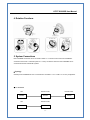
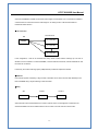
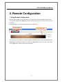
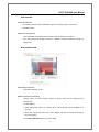
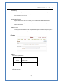
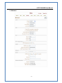
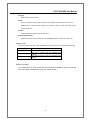
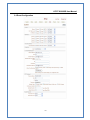
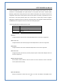
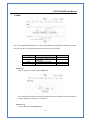
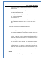
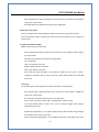
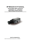
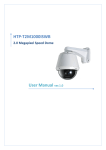
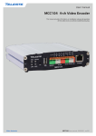
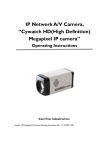
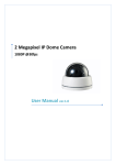
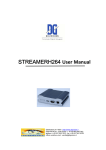
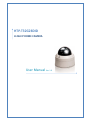
HTP‐T32G28DID H.264 IP DOME CAMERA User Manual Ver. 1.0 HTP-T32G28DID User Manual Safety Precaution We appreciate your purchasing HTP-T32G28DID. Before installing the product, please read the following with care. Make sure to turn off the power before installing HTP-T32G28DID. Do not install under the direct sunlight or in dusty areas. Make sure you use the product within the temperature and humidity specified in the specification. Do not operate the product in the places with vibration or strong magnetic fields. Do not put electrically conductive materials into the product unless specified in the manual. Do not open the top cover of the product. It can cause an static shock and damage the components. In order to prevent overheating, make sure there is at least 10 cm of space between the wall and the product. After checking rated voltage, please connect the power. -1- HTP-T32G28DID User Manual Table of contents 1. Introduction ...................................................................................................................................... 3 1. About User Manual.................................................................................................................... 3 2. Features .................................................................................................................................... 3 3. Product and Accessories ........................................................................................................... 4 4. Rotation Functions .................................................................................................................... 5 5. System Connections ................................................................................................................. 5 2. Installation ........................................................................................................................................ 7 1. Connecting Network (LAN)........................................................................................................ 7 2. Connecting Audio ...................................................................................................................... 7 3. Connecting Serial Ports............................................................................................................. 7 4. Connecting Sensor & Alarm ...................................................................................................... 7 5. Connecting Power ..................................................................................................................... 8 6. Checking Operating................................................................................................................... 8 3. System Operation............................................................................................................................. 9 1. Remote Video Monitoring ...................................................................................................... 9 2. Initialization of IP Address ....................................................................................................... 11 4. Remote Configuration..................................................................................................................... 12 1. Using Remote Configuration ................................................................................................... 12 2. HTP-T32G28DID Setup........................................................................................................... 13 2.1 System ........................................................................................................................... 13 2.2 Video.............................................................................................................................. 15 2.3 Audio .............................................................................................................................. 18 2.4 Network .......................................................................................................................... 19 2.5 Serial Port Configuration ................................................................................................ 22 2.6 Event Configuration........................................................................................................ 24 2.7 Preset............................................................................................................................. 27 2.8 User ............................................................................................................................... 28 2.9 Camera .......................................................................................................................... 29 5. APPENDIX : PoE Specification................................................................................................ 33 -2- HTP-T32G28DID User Manual 1. Introduction 1. About User Manual The User Manual is provided to advise how to use this premium network camera, HTP-T32G28DID. This manual includes how to trouble shoot in case of problems as well as installation, operation and setting up the HTPT32G28DID. 2. Features HTP-T32G28DID is a network-based dome camera with remote live monitoring, audio monitoring and control via an IP network such as LAN, ADSL/VDSL, and Wireless LAN. Video - Highly efficient compression algorithm, H.264 & MJPEG dual streaming support - Compression in various resolution: QCIF, CIF, Half-D1, D1 - Wide range of transmission rates: 32kbps ~ 8Mbps - Various transmission modes: CBR, VBR - Motion detection Audio - Multi-transmission mode: Simplex (HTP-T32G28DID Æ Client PC or Decoder, Client PC or Decoder Æ HTP-T32G28DID), Full Duplex Network - Fixed IP & Dynamic IP (DHCP) support - 1:1, 1:N support - Multicasting - Automatic transmit rate control according to network conditions Serial Data - RS-485 support - Data pass-through mode: serial data communications between HTP-T32G28DID and Decoder -3- HTP-T32G28DID User Manual Sensor & Alarm - Support direct connections of external sensor and alarm devices. - Event alarm User Interface - Diagnose and upgrade through dedicated program called True Manager - System configuration using Internet Explorer High Reliability - Embedded system - System recovery by dual Watch-dog functions 3. Product and Accessories HTP-T32G28DID System User Manual S/W CD <Picture 1> Package -4- HTP-T32G28DID User Manual 4. Rotation Functions 5. System Connections HTP-T32G28DID IP Cameras can be connected in either 1 to 1 connection where one HTP-T32G28DID is connected one PC client or a decoder system or 1 to many connections where one HTP-T32G28DID can be connected several PCs and decoder systems. Topology Generally HTP-T32G28DID and a PC or a decoder are connected in a 1 to 1 mode or a 1 to many configuration. 1:1 connection Site Remote Center Remote Center Camera Decoder Monitor Site Remote Center Camera PC -5- HTP-T32G28DID User Manual One HTP-T32G28DID is installed at a site where video images are transmitted. A PC or a decoder is installed at a central location to receive and view the video images on an analog monitor. Audio and serial data are transferredin either direction. 1:N connection Remote Center Site PC or Decoder Camera PC or Decoder PC or Decoder In this configuration, a site can be monitored from many remote central locations. Although up to 64 PCs or decoders can be connected to on HTP-T32G28DID, in the real network environment, network bandwidth can limit the maximum connections. Functionally, the central monitoring system (CMS) software provided can replace the decoder Multicast If the network supports multicasting, a large number of decoders can be used to receive video effectively from a HTP-T32G28DID using a single streaming of video and audio. Relay Site Center 1 Center 2 Camera Decoder Decoder Video and audio can be retransmitted from a center to another center. The arrangement is useful when the network bandwidth to the site is limited while there are more than one center want to monitor the site. -6- HTP-T32G28DID User Manual CMS (Central Monitoring System) Site Remote Center Camera CMS Site Remote Center Camera Decoder CMS CMS is a Window-based remote monitoring program in order to monitor or control video, audio, and events in real time from several IP cameras or video servers. Please refer to the CMS User Manual for more in detail. 2. Installation 1. Connecting Network (LAN) - Connect the power adaptor to HTP-T32G28DID - Connect network cable to Ethernet port. 2. Connecting Audio Audio is full-duplex. It is possible to set the mode as Tx-only, Rx-only or Tx-Rx. - Connect audio input and output ports to audio devices accordingly. - The Audio signal required is line level, so audio equipment with an amp, mixer or other amplifier should be used. 3. Connecting Serial Ports RS-485 of HTP-T32G28DID can be connected to external equipment such as PT receiver etc. PC client can send PT commands to the external equipment via the serial port. When a decoder system instead of PC client is connected to HTP-T32G28DID, the serial port and that of the decoder system works in pass-through mode. That is, data from at one port is delivered to the other port, vice versa . 4. Connecting Sensor & Alarm Connect sensor and alarm devices to corresponding terminals accordingly -7- HTP-T32G28DID User Manual 5. Connecting Power After confirming the power source, connect power adaptor and then 12V DC connector to the system. 6. Checking Operating Once the power is supplied to the camera, it will start booting. The system will boot up to an operating mode after approximately 40-60 seconds. The green LED on the Ethernet port will flash indicating the system is ready. Software provided on the disc called True Manager allows you to check the IP address and other network details of the camera. Please refer to the True Manager manual for instructions on how to find the IP address of the camera and if required changing it. -8- HTP-T32G28DID User Manual 3. System Operation 1. Remote Video Monitoring There are two ways to monitor video when the decoder site and HTP-T32G28DID are connected. IP address should be correct, please refer to True Manager Manual and Remote Setting in Chapter 5 for further details. Default ID : admin Password : 1234 Video Monitoring via Decoder System Once the HTP-T32G28DID’s IP address is set in the remote IP address section of the decoder, the decoder system will connect to the HTP-T32G28DID and start receiving the video images. Normally, a monitor connected to the decoder will display video images. Video Monitoring by Internet Explorer If HTP-T32G28DID’s IP address is entered in to Internet Explorer, the system will ask for confirmation to install Active-X control. Once authorized, Internet Explorer will start to display video images from the encoder as shown below. http://192.168.10.100 -9- HTP-T32G28DID User Manual Video Selection HTP-T32G28DID is capable of dual streaming. Video Selection allows you to choose Primary Video image or Secondary Video image. Video Image is displayed according to the resolution set on video configuration. When dual streaming is not activated and secondary mode is selected, video cannot be displayed. Screen Size: Adjustable Screen Size Digital Zoom: Max 5x Digital Zoom is available. Focus Near, Focus Far, Auto Focus Adjust the focus Sensor Input When the sensor on the HTP-T32G28DID is connected and working, the light turns red. Alarm Output Alarm Output button can trigger an event directly from the Live View page. Snapshot Snapshot button saves a snapshot of the video image currently on display. Captured picture can be stored as BMP or a JPEG file. Talk Transfer audio to audio device connected HTP-T32G28DID. -10- HTP-T32G28DID User Manual 2. Initialization of IP Address If HTP-T32G28DID’s IP address is lost, the HTP-T32G28DID can be reset. Press a reset button on the back of the HTP-T32G28DID, this will reset the camera to factory defaults as follows: c While the system is in operation, press the reset button for more than 5 seconds. d The system will reboot automatically e Once the system has been rebooted, IP address will be set to the following. - IP mode: Fixed IP - IP address: 192.168.10.100 - Subnet mask: 255.255.255.0 - Gateway : 192.168.10.1 - Base port : 2222 - Http port : 80 -11- HTP-T32G28DID User Manual 4. Remote Configuration 1. Using Remote Configuration Remote setting is available by using web browser. Enter the IP address of HTP-T32G28DID and then live view screen appears as below. Press Setup button located in the upper right area of the monitoring screen to go to the server setup. For Remote Setting, user should be authorized higher than manager level. c Enter IP Address d Press Setup button The configurations are grouped into 9 categories: System, Video, Audio, Network, Serial, Event, Preset, User and Camera. Any configuration changes are not applied until Apply button is pressed. Leaving the page without pressing Apply button, changes in the page will be discarded. -12- HTP-T32G28DID User Manual 2. HTP-T32G28DID Setup 2.1 System -13- HTP-T32G28DID User Manual System ID Designate system ID. Designated ID is displayed in Web viewing. Language Select language accordingly. Firmware Version Displayed current Firmware Version Board ID Network board ID of HTP-T32G28DID recognized by system Start Time Latest system boot date and time Current Time Current date & time: enter a new date and time and press Set Current Time button to update date & time. Time Zone Select time zone where the system is installed. Depending on the time zone, Daylight-saving time will be adjusted automatically. Automatic synchronization with NTP Synchronize system time with an NTP server using NTP (network time protocol). Name of the NTP server should be registered on NTP server Name. Reboot System Pressing Reboot Server button will cause the system to reboot. Do not press the Reboot button unless the server needs a reboot . Factory Reset Current IP Address of HTP-T32G28DID is changed to default IP Address, 192.168.10.100. System log and user registrations are also cleared. The other setting value will be remained. -14- HTP-T32G28DID User Manual 2.2 Video -15- 4 HTP-T32G28DID User Manual - ENCODE Input Format Choose video type to be used between composite NTSC or composite Resolution Selectable video compression resolution as below: NTSC: 720X480, 720x240, 352X480, 352X240, 176X120 PAL: 720X576, 720X288, 352X576, 352X288, 176X144 Frame Rate Select video frame rate (the maximum number of frames of video images to compress.) The frame rate actually transmitted can be affected by the network bandwidth limitations. Preference Preference in video compression and transmission: With ‘Bitrate’ selected, the video compression will be effected by the ‘Bitrate’ value entered. With‘Quality’ selected, the video compression will be effected by the quality of image selected. Therefore, ‘Bitrate’ and ‘Quality’ corresponds to CBR (Constant Bitrate) and VBR (Variable Bitrate) respectively. Quality VBR (Variable Bit Rate) adjusts the bit rate according to the image complexity, using up bandwidth for increased activity in the image and less for lower activity in the monitored area. Bitrate CBR (Constant Bit Rate) allows you to set a fixed target bit rate that consumes a predictable amount of bandwidth. As the bit rate would usually need to be increased for increased image activity, but in this case it is constrained, the frame rate and image quality are affected negatively. I-Frame Interval Setting numbers of P frames to each I frame between 0 and 255. There will be no P-frame if 0 is set. -16- HTP-T32G28DID User Manual - DUAL ENCODE Use Dual Encode The Selection between H.264 and MJPEG is supported. Secondary Video can be used on Live View window Dual Encode Algorithm H.264 and MJPEG can be selected for secondary streaming. Maximum resolution is 720 x 480 and there are 8 steps of resolution. If MJPEG is selected, Preference supports only Quality mode. - MOTION DETECTION Use Motion Detection Select Motion Detection function Motion Detection Area Editing Configure regions for motion detection. Regions of arbitrary shape can be configured by the following steps. c Enable Edit item. d Select editing Mode. Set is for including cells to motion detection region and Erase is for excluding. e Select cells using the left button of the mouse. Multiple cells can be selected conveniently by press and dragging. f Press Apply Edited Area button to save the editing. -17- HTP-T32G28DID User Manual Sensitivity A condition to trigger an event of motion detection. The value determines the sensitivity of the motion detection within a block: the smaller, the more sensitive. It is selectable from from 0 to 10. Information Display System ID and/or server time can be display over the video window in Web View. Each item can be turn on or off and position can be configure as well. This information is displayed after the video is decompressed. Burn-in OSD Insert system ID and date/time in the compressed video. System ID and time respectively can be turned on or off in the video. And position and Font size can be selectable. 2.3 Audio Mode Select audio operation mode. Mode Action Off No operation Tx-Only Transmit only Rx-Only Receive only Tx & Rx Transmit and Receive Input Gain Set audio input gain. -18- HTP-T32G28DID User Manual 2.4 Network -19- HTP-T32G28DID User Manual IP Mode Two IP modes are supported. Depending on the selected mode, further configuration items come as follows. IP Mode Fixed IP DHCP IP Selection Description Local IP Local Gateway Local Subnet N/A Fixed IP address Gateway IP address Subnet mask ☞ Please get IP address information from your ISP provider or network manager. DNS Set DNS server IP address. Base Port Network base port is used for communication between systems. In order for the HTP-T32G28DID and remote systems to be connected together, each port number must be identically set. HTTP Port HTTP port used for web-based connection RTSP Port RTSP port used for RTSP-based connection SNMP HTP-T32G28DID can be used as an SNMP agent. It is compatible to both SNMPv1 and SNMPv2c. Vender specific MIBs for IP camera/server are defined. SNMP listen port can be set and disabled when it is 0. SNMP trap is also supported. Destination IP and port can be set. If one of these values is 0, SNMP trap will be disabled. Multicast IP The multicast IP address selection range is between 224.0.1.0 and 238.255.255.255. The selection can be used only when media protocol is set to Multicast. The multicast address must be the same for the system to be connected using multicast protocol. DDNS -20- HTP-T32G28DID User Manual Select the DDNS(Dynamic DNS) server to use. One of the two servers can be selected. - TrueDNS : use TrueDNS service. Systems can be registered on the website for TrueDNS service: http://ns1.truecam.net. System will get a domain name of xxx.truecam.net style. Refer to the user guide document for True DNS service. - DynDNS : use DynDNS service. Refer www.dyndns.org for details. Address Information Tree addresses are checked by 3 ways below. (Read-only). IP Address The servers own IP address. This information is useful when the server’s IP mode is set to DHCP. Domain Name In case the server is registered with DDNS server, the registered domain name is displayed. MAC Address Display the MAC address of the server. In case the server is registered with DDNS server, the MAC address is used in DDNS registration. -21- HTP-T32G28DID User Manual 2.5 Serial Port Configuration Serial Port Configuration There is one serial port, RS-485 in HTP-T32G28DID. The serial port can be configured as follows Mode Bitrate Data Bits Parity Stop Bit Selection 2400, 4800, 9600, 19200, 38400, 57600, 115200 bps 5, 6, 7, 8 bits NONE, EVEN, ODD bit 1, 2 bit The serial ports configurations must be same as connecting device. PTZ -22- HTP-T32G28DID User Manual PTZ Type Select the type of PTZ receiver. PTZ ID Since it is possible to control multiple receivers over a single control line, each receiver will be assigned with a unique ID. Enter PTZ ID of a receiver for control. The ID value range can be between 0 and 255. PTZ Port Select the serial port used for PTZ camera control. Direct Keyboard Control Keyboard controller can be connected to HTP-T32G28DID directly to control zoom and focus. Sensor Type There is one sensor input port on HTP-T32G28DID. The sensor port can be configured to the following. Function OFF NO (Normally Open) NC (Normally Closed) Operation Not used The port is normally open and activated when closed. The port is normally closed and activated when opened. The function of the sensor port is set based on the type of the sensor connected. Sensor Schedule If you select sensor on, Each sensor port can be enabled or disabled by day(of a week) and hour units. Sensor is disabled during the grey-colored duration. -23- HTP-T32G28DID User Manual 2.6 Event Configuration -24- HTP-T32G28DID User Manual The HTP-T32G28DID has one sensor port and one alarm port. When a decoder system instead of a PC client is connected to a HTP-T32G28DID, one system becomes a Local system and the other a Remote system (Generally a system which is being used by the user is called as Local system). Then, actions for events can be configured for events from the remote system as well as for local system. For example, it is possible to turn on an alarm device in local (center) decoder system when a sensor device in remote (site) IP camera is triggered. Local section configures the actions for events from local (self) system, and configuration activates local devices and Remote sections configure the actions for events from remote (peer) system. . The following table lists the possible actions for events. Action Sensor In Alarm out E-mail FTP Description One sensor in port Triggers alarm (relay) port. Sends E-mail to the specified address. AVI file can be attached Upload AVI file to a specified FTP server Sensor Configure the actions when the sensor is activated. Multiple actions can be set for a single event. On Video Loss Configure the actions when video input signal is lost. Multiple actions can be set for a single event. On Motion Configure the actions when motion is detected. Multiple actions can be set for a single event. On Disconnect Configure the actions when the link (connection) with peer system is disconnected. Multiple actions can be set for a single event. Alarm activation duration Set the duration of alarm activation in case of an event. If it is set to continuous, it will be in active state until an operator reset it manually. E-mail Notification Specify the information to send E-mail as the action of an event. The address of mail (SMTP) server -25- HTP-T32G28DID User Manual needs to be specified on Server Address field, and Port specifies the port for SMTP operation (Port 25 is the default port in SMTP operation. If a different port is configured in the SMTP server, this port needs to be changed accordingly). When the server requires authentication, ID and password of an E-mail account needs to be entered also. Destination address needs to be entered on Destination Address field. More than one address can be entered by delimiting comma (,) or semi-colon (;). Destination address can take up to 63 characters. Video clip of AVI file format or JPEG file at the moment of the event can be attached by setting Video Clip Attaching. FTP Upload Specify the information for uploading a video file as the action of an event. The address of an FTP server to receive video files is specified on Server Address field, and Port specifies the port for FTP operation (Port 21 is the default port in FTP operation. If different port is configured in the FTP server, this port needs to be changed accordingly.). ID and password for accessing the FTP server also need to be specified. Video clip of AVI file format or JPEG file at the moment of the event can be attached by setting Video Clip Attaching. By setting Continuous Upload to On, it is possible to upload video clip periodically regardless of events. Upload Duration specifies the duration of one upload file, and Upload Interval specifies how often it should happen. Upload Interval doesn’t include the duration. If Upload Interval is 60 and Upload Duration is 20, it uploads a file for 20 seconds duration every 80 seconds. Event Recording Specify how a video clip is to be generated for E-mail sending or FTP uploading. Pre-event Time specifies the duration of recording before an event happens. Post-event Time specifies the duration after the event is cleared. -26- HTP-T32G28DID User Manual 2.7 Preset d Preset Name c Move PTZ Camera to normal view f Save e Press Set Button This function is only available when a PTZ receiver is used with HTP-T32G28DID. Configure up to 15 preset positions. Preset function is not available on some PTZ receivers. Make sure to check if a PTZ receiver supports preset. Preset Configuration Set the PTZ Presets by following the next steps. c Move cameras to desired view using PTZ control buttons. d Enter Preset name. e Press Set button. f Once all the presets are set, press Save List button. Move to Preset Position Select a preset from the Preset and press Go To button, then, the camera will move to the selected preset position. -27- HTP-T32G28DID User Manual 2.8 User User can be registered and privilege level of a user can be specified. User configuration is allowed only to admin user. Max 16 users can be registered and each user can have one of four privileges. Privilege Admin Manager User Guest Allowed Operations All operations All operations except for user configuration Live viewing and PTZ control Live viewing only Remarks User ID = admin Add User Page for adding a user comes on pressing Add button. User ID and password need to be entered and privilege level need to be selected. User ID and password consist of alphanumeric string of max 15 characters. Delete User A user is deleted by pressing Delete button. -28- HTP-T32G28DID User Manual Change Password Pressing Modify Password button after selecting a user shows a page for changing password. In case changing admin password, old password is checked. Modify Privilege Level Pressing Modify Privilege button after selecting a user shows a page for changing the privilege. It is not allowed to change the privilege level of admin user. Login Policy Skip Login is provided for convenient access to the server when authentication is not required. When Skip Login is set to Enable, login step is skipped. The privilege level after login in this way is determined by the setting of Privilege Level After Login Skipped. 2.9 Camera -29- HTP-T32G28DID User Manual Settings for analog part of the camera can be configured. Camera-specific menu is displayed using OSD on video display, and this menu can be operated with 5 buttons on the page. OSD (On Screen Display) How to use z Press the Set button to access the SETUP mode. z Select the desired feature using the Up or Down button. z Change the status of the selected feature using the Left or Right button. z When completed, move the arrow indicator to ‘EXIT’ and press the Set button Setting up the LENS Select the lens pressing the Right button. On the SETUP menu screen, move the arrow indicator to the lens using the UP or DOWN button. Select the desired feature using the LEFT or RIGHT button. When DC lens selected, press Set button to control the brightness. Auto Iris Lens (DC Type) is recommended than Manual Lens. Some lens can make a malfunction according to the Brightness Level. Shutter status and speed control You can control brightness of the screen by the shutter speed. -30- HTP-T32G28DID User Manual Press the Set button to display the setup menu and move the arrow indicator to ‘SHUTTER’ using the Up or Down button. Set ‘SUTTER’ to the desired mode using the Left or Right button. Off : Deactivation, FLK (1/100) : Flicker mode When WDR is on, the image can flicker a little. When setting shutter speed manually (Only for Lens mode), you can select speed from ‘1/60’ to 1/200,000’sec. ESC : You can control the BRIGHTNESS. When completed, press ‘SET’ Do not make the camera exposed fluorescent lamp directly not to get unstable image in the internal synchronization modes. When the SHUTTER menu is set to FLK mode, SENS-UP can not work, please control the menu. White Balance (White BAL) When it needs color control on the screen, use ‘WHITE BALANCE’ function. Press the SET button to display the SETUP menu and move the arrow indicator to ‘WHITE BALANCE’ using Up or Down button. Set ‘WHITE BAL.’ to the desired mode using Left or Right button. ATW (Auto Tracking White Balance) : When color temperature is 2400~12,000k, select this mode. (Ex. A fluorescent lamp, outdoor) AWC (Auto White Balance Control) : The white balance is automatically adjusted in a specific environment. In order to obtain the best result, press the set button while the camera focuses on the white paper. If the environment including the light source is changed, you have to adjust the white balance again. Manual : To find adjust, select the Manual mode. You can increase or decrease the red or blue factor while monitoring the difference on the screen. Set to ‘Manual’ mode and press the Set button. Increase or decrease the value for RED (R-Gain) and BLUE (B-Gain), watching the color of the picture, and press the Set button when you obtain the best color. Proper White Balance may not be obtained under the following conditions in these cases select the AWC mode; when the scene contains mostly high color temperature object, such as a blue sky or sunset. When the scene is dim. If your camera faces fluorescent lamp directly or is installed in the place of the changing illumination. Backlight SR chip built-in provides intelligent light level control to overcome the sever Backlight condition. -31- HTP-T32G28DID User Manual Press the Set button to display the SETUP menu and move the arrow indicator to ‘BACKLIGHT’ using the Up or Down button. Set ‘BACKLIGHT’ to the desired mode using the Left or Right button Auto Gain Control (AGC) AGC is to get bright picture. Higher GAIN level, brighter screen. But you can get noise increase. Press the Set button to display the SETUP menu and move the arrow indicator to ‘AGC’ using the Up or Down button Digital Noise Reduction (DNR) DNR is to reduce the noise on the screen. Press the Set button to display the SETUP menu and move the arrow indicator to ‘DNR’ using the Up or Down button. Set ‘DNR’ to the desired mode using the Left or Right button. OFF : Deactivation LOW : Low reduction of the noise MIDDLE : Middle reduction of the noise HIGH : High reduction of the noise After image may appear with DNR. If you change the ‘GAIN’ menu from AGC-L to AGC-H, sensitivity is increased as well as noise on the screen. When selected ‘GAIN’ menu OFF, DNR will not work Sens-Up You can always get the clear image with this function under night or low lighting level. Press the Set button to display the SETUP menu and move the arrow indicator to ‘SENSE UP’ using the Up or Down button. Set ‘Sense Up’ to the desired mode using the Left or Right button. AUTO : When your camera is under night or low-lighting level, select this mode. If you press SETUP button at ’AUTO’ menu, you can control the lowlight action maximum magnifications.(X2~X128) Expander the magnifications, you can get the brighter screen as well as the after image sensitivity is increased as well as noise on the screen. When increasing the magnifications in case of SENSE UP activated, it may appear noise, spots, -32- HTP-T32G28DID User Manual whitish. This is not out of order SPECIAL CAMERA ID : If the camera ID feature is set to ‘OFF’, the name will not displayed in the monitor. However, Camera ID can be set on the System tap of web viewer. Color: You can choose color and B/W mode electronically. (Option) On: Color mode, OFF : B/W mode, Auto : Generally color mode, B/W mode in low luminance. SYNC: Two SYNCHRONIZATION modes are available INTERNAL and EXTERNAL LINE-LOCK. In LINE-LOCK mode, it synchronous generator. The line-lock synchronization is only used in the area of 60Hz(NTSC Models) 50Hz(PAL Models). When it used in AC power, L/L mode can be used. In DC 12V, the SYNC menu sets ‘INT’ mode. Whenever your camera detects motion of object displaying ‘MOTION DETECTED’ with the number counted up on the screen. OFF: Deactivation ON: MOTION DET. Activated. - Press SET button - Move the arrow indicator to ‘AREA SET’ using Up and Down button, and then press the Set button. - Set the areas you want to observe. PRIVACY : To mask area which you want to mask. OFF: Deactivation ON: PRIVACY mode activated. - Press the Set button - Move the arrow indicator to area you want to mask. - Set ‘ON’ using Left or Right button - Press the Set button and then set the area’s bounds with method like MOTION DET. Set. MIRROR : OFF : Deactivation, ON : Make a reverse turn to Right or Left SHARPNESS - OFF: Deactivation - ON: SHARPNESS control mode (LEVEL 0~31) - When level is up, the sharpness will make image clear. Please control the level as you want to get. If the level is to much high, you can get the unnatural image with noise. RESET: To reset your camera to FACTORY DEFAULT SETTING. RETURN: Save the setting of SPECIAL function, and then move to SET UP menu. 5. APPENDIX : PoE Specification z IEEE802.3af compliant -33- HTP-T32G28DID User Manual z Output Voltage : 12.0V z Input voltage range : 36V to 57V z 1500V isolation (input to output) . PoE must be protected from over-voltages exceeding the 80V maximum rated surge input voltage 1. Recommended Operating Conditions Parameter Min Typ Max Units 48 57 V 36 V 1 DC Supply Voltage 36 2 DC Voltage Lockout 30 3 Operating Temperature -20 25 70 Ta/°C Parameter Min Typ Max Units 1 Nominal Output Voltage 11.5 12.0 12.5 V 2 Output Current (VIN = 48V) 1.0 A 3 Line Regulation 0.1 % 4 Load Regulation 1 % 5 Output Ripple and Noise 100 mVp-p 6 Minimum Load 7 Short-Circuit Duration 8 Efficiency @ 80% Load 9 Isolation Voltage (I/O) 10 Temperature Coefficient 2. DC Electrical Characteristics mA 100 ∞ sec % 87 1500 0.02 Vdc % Note 1: Typical figures are at 25°C with a nominal 48V supply and are for design aid only. Not Guaranteed 2: The output ripple and noise can be reduced with an external filter, see application note. 3: Continuous short circuit duration is applicable at 25'C ambient temperature in free air. At higher temperatures or with restricted airflow (e.g. in a sealed enclosure) the duration will need to be limited to avoid overheating. -34-