1
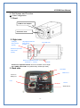
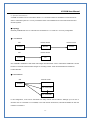
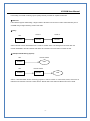
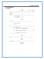
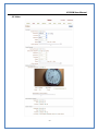
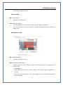
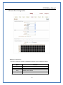
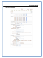
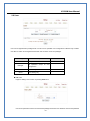
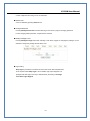
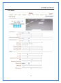
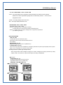
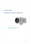
Network Camera VC58SM User Manual VC58SM User Manual Safety Precaution We appreciate your purchasing IP series. Before installing the product, please read the following with care. Make sure to turn off the power before installing VC58SM Do not install under the direct sunlight or in dusty areas. Make sure you use the product within the temperature and humidity specified in the specification. Do not operate the product in the places with vibration or strong magnetic fields. Do not put electrically conductive materials into the product unless specified in the manual. Do not open the top cover of the product. It can cause an static shock and damage the components. In order to prevent overheating, make sure there is at least 10 cm of space between the wall and the product. After checking rated voltage, please connect the power. -1- VC58SM User Manual Table of contents 1. About User Manual ............................................................................................... 3 2. Features ............................................................................................................. 3 3. Product and Accessories....................................................................................... 4 4. Product Overview .............................................오류! 책갈피가 정의되어 있지 않습니다. 5. System Connections ............................................................................................. 6 2. Installation ................................................................................................................ 8 1. Connecting Network (LAN) .................................................................................... 8 2. Connecting Audio................................................................................................. 8 3. Connecting Serial Ports ......................................................................................... 8 4. Connecting Sensor & Alarm ................................................................................... 8 5. Connecting Power ................................................................................................ 8 6. Checking Operating .............................................................................................. 8 3. System Operation ....................................................................................................... 9 1. Remote Video Monitoring ................................................................................... 9 2. Initialization of IP Address .................................................................................... 11 4. Remote Configuration ................................................................................................ 12 1. Using Remote Configuration ................................................................................. 12 2. VC58SM Setup .................................................................................................... 13 2.1 System ....................................................................................................... 13 2.2 Video ......................................................................................................... 15 2.3 Audio ......................................................................................................... 18 2.4 Network ...................................................................................................... 19 2.5 Serial Port Configuration ............................................................................... 22 2.6 Event Configuration ..................................................................................... 24 2.7 Preset ........................................................................................................ 27 2.8 User .......................................................................................................... 28 2.9 Camera ...................................................................................................... 30 -2- VC58SM User Manual Introduction 1. About User Manual The User Manual is provided to advise how to use this premium network camera, VC58SM This manual includes how to trouble shoot in case of problems as well as installation, operation and setting up the VC58SM 2. Features VC58SM is a 1.3 Megapixel network-based camera with remote live monitoring, audio monitoring and control via an IP network such as LAN, ADSL/VDSL, and Wireless LAN. Video - Highly efficient compression algorithm, H.264 & MJPEG support - 18 kinds of compression and resolutions: 352x240 ~ 1280 x 1024 - Wide range of transmission rates: 32kbps ~ 8Mbps - Various transmission modes: CBR, VBR - Motion detection Audio - Multi-transmission mode: Simplex (VC58SM Client PC or Decoder, Client PC or VC58SM), Full Duplex Network - Fixed IP & Dynamic IP (DHCP) support - 1:1, 1:N support - Multicasting - Automatic transmit rate control according to network conditions Serial Data - RS-485 support - Data pass-through mode: serial data communications between VC58SM and Decoder Sensor & Alarm - Support direct connections of external sensor and alarm devices. - Event alarm -3- Decoder VC58SM User Manual User Interface - Diagnose and upgrade through dedicated program called True Manager - System configuration using Internet Explorer High Reliability - Embedded system - System recovery by dual Watch-dog functions 3. Product and Accessories VC58SM System User Manual S/W CD <Picture 1> Package -4- VC58SM User Manual 4. Part Names and Function ◆ Cable Configuration 1. Front C-Mount lens adaptor Protective cover 2. Right side Intelligent Photo sensor (Inside) Day/Night mechanical filter changer (Inside) Auto IRIS conn. Widelux Super WDR CCD sensor (Inside) Back focus adjustment Knob (Tolerance +, - 0.5mm) Fixture - Back focus adjustment Knob: Fine tune the Back Focal Length - DC / VIDEO Select S/W: UP (VIDEO IRIS), DOWN (DC IRIS) 3. Back side SD CARD VIDEO OUT Sensor In Relay out LAN DC12V Audio in/out -5- VC58SM User Manual 5. System Connections VC58SM IP Cameras can be connected in either 1 to 1 connection where one VC58SM is connected one PC client or a decoder system or 1 to many connections where one VC58SM can be connected several PCs and decoder systems. Topology Generally VC58SM and a PC or a decoder are connected in a 1 to 1 mode or a 1 to many configuration. 1:1 connection Site Remote Center Remote Center VC58SM Decoder Monitor Site Remote Center VC58SM PC One VC58SM is installed at a site where video images are transmitted. A PC or a decoder is installed at a central location to receive and view the video images on an analog monitor. Audio and serial data are transferred in either direction. 1:N connection Site VC58SM Remote Center PC or Decoder PC or Decoder PC or Decoder In this configuration, a site can be monitored from many remote central locations. Although up to 64 PCs or decoders can be connected to on VC58SM, in the real network environment, network bandwidth can limit the maximum connections. -6- VC58SM User Manual Functionally, the central monitoring system (CMS) software provided can replace the decoder Multicast If the network supports multicasting, a large number of decoders can be used to receive video effectively from a VC58SM using a single streaming of video and audio. Relay Site Center 1 Center 2 VC58SM Decoder Decoder Video and audio can be retransmitted from a center to another center. The arrangement is useful when the network bandwidth to the site is limited while there are more than one center want to monitor the site. CMS (Central Monitoring System) Site Remote Center VC58SM CMS Site Remote Center VC58SM Decoder CMS CMS is a Window-based remote monitoring program in order to monitor or control video, audio, and events in real time from several IP cameras or video servers. Please refer to the CMS User Manual for more in detail. -7- VC58SM User Manual 2. Installation 1. Connecting Network (LAN) - Connect the power adaptor to VC58SM - Connect network cable to Ethernet port. 2. Connecting Audio Audio is full-duplex. It is possible to set the mode as Tx-only, Rx-only or Tx-Rx. - Connect audio input and output ports to audio devices accordingly. - The Audio signal required is line level, so audio equipment with an amp, mixer or other amplifier should be used. 3. Connecting Serial Ports RS-485 of VC58SM can be connected to external equipment such as PT receiver etc. PC client can send PT commands to the external equipment via the serial port. When a decoder system instead of PC client is connected to VC58SM, the serial port and that of the decoder system works in pass-through mode. That is, data from at one port is delivered to the other port, vice versa . 4. Connecting Sensor & Alarm Connect sensor and alarm devices to corresponding terminals accordingly 5. Connecting Power After confirming the power source, connect power adaptor and then 12V DC connector to the system. 6. Checking Operating Once the power is supplied to the camera, it will start booting. The system will boot up to an operating mode after approximately 40-60 seconds. The green LED on the Ethernet port will flash indicating the system is ready. Software provided on the disc called True Manager allows you to check the IP address and other network details of the camera. Please refer to the True Manager manual for instructions on how to find the IP address of the camera and if required changing -8- VC58SM User Manual 3. System Operation 1. Remote Video Monitoring There are two ways to monitor video when the decoder site and VC58SM are connected. IP address should be correct, please refer to True Manager Manual and Remote Setting in Chapter 5 for further details. Default ID : admin Password : 1234 Video Monitoring via Decoder System Once the VC58SM’s IP address is set in the remote IP address section of the decoder, the decoder system will connect to the VC58SM and start receiving the video images. Normally, a monitor connected to the decoder will display video images. Video Monitoring by Internet Explorer If VC58SM’s IP address is entered in to Internet Explorer, the system will ask for confirmation to install Active-X control. Once authorized, Internet Explorer will start to display video images from the encoder as shown below. http://192.168.10.100 Video Selection -9- VC58SM User Manual If Primary is selected, Max. 1920 x 1080 via H.264 compression algorithm video can be displayed. And once activated Dual Video compression and Secondary may be selected, Max. D1 resolution via H.264 or MJPEG compression algorithm video can be displayed in this case. . Screen Size: Adjustable Screen Size Digital Zoom: Max 5x Digital Zoom is available. Focus Near, Focus Far, Auto Focus Adjust the focus Sensor Input When the sensor on the VC58SM is connected and working, the light turns red. Alarm Output Alarm Output button can trigger an event directly from the Live View page. Snapshot Snapshot button saves a snapshot of the video image currently on display. Captured picture can be stored as BMP or a JPEG file. Talk Transfer audio to audio device connected VC58SM -10- VC58SM User Manual 2. Initialization of IP Address If VC58SM’s IP address is lost, the VC58SM can be reset. Press a reset button on the back of the VC58SM, this will reset the camera to factory defaults as follows: While the system is in operation, press the reset button for more than 5 seconds. The system will reboot automatically Once the system has been rebooted, IP address will be set to the following. - IP mode: Fixed IP - IP address: 192.168.10.100 - Subnet mask: 255.255.255.0 - Gateway : 192.168.10.1 - Base port : 2222 - Http port : 80 -11- VC58SM User Manual 4. Remote Configuration 1. Using Remote Configuration Remote setting is available by using web browser. Enter the IP address of VC58SM and then live view screen appears as below. Press Setup button located in the upper right area of the monitoring screen to go to the server setup. For Remote Setting, user should be authorized higher than manager level. Enter IP Address Press Setup button The configurations are grouped into 9 categories: System, Video, Audio, Network, Serial, Event, Preset, User and Camera. Any configuration changes are not applied until Apply button is pressed. Leaving the page without pressing Apply button, changes in the page will be discarded. -12- VC58SM User Manual 2. VC58SM Setup 2.1 System -13- VC58SM User Manual System ID Designate system ID. Designated ID is displayed in Web viewing. Language Select language accordingly. Firmware Version Displayed current Firmware Version Board ID Network board ID of VC58SM recognized by system Start Time Latest system boot date and time Current Time Current date & time: enter a new date and time and press Set Current Time button to update date & time. Time Zone Select time zone where the system is installed. Depending on the time zone, Daylight-saving time will be adjusted automatically. Automatic synchronization with NTP Synchronize system time with an NTP server using NTP (network time protocol). Name of the NTP server should be registered on NTP server Name. Reboot System Pressing Reboot Server button will cause the system to reboot. Do not press the Reboot button unless the server needs a reboot . Factory Reset Current IP Address of VC58SM is changed to default IP Address, 192.168.10.100. System log and user registrations are also cleared. The other setting value will be remained. -14- VC58SM User Manual 2.2 Video -15- VC58SM User Manual - ENCODE Enable Preview Turn on to transmit the video direct to HD monitor and select the one of Output Formats in the end of the Video setting section. *Scaling: If the encoding resolution was different from the input resolution, encoding video was cropped. In the scale mode, whole visual region of input source will be encoded even when the encoding resolution is smaller than the input video resolution. However, if the aspect ratio of of the encoding resolution is different from the input resolution, distortion can be seen. Also it is possible that the quality of video will deteriorate during the process of scaling. Resolution Selectable video compression resolution as below: 1280 x 960, 1280 x 720, 1024 x 768, 800 x 600, 640 x 480, 352 x 288, 352 x 576, 720 x 288, 720 x 576, 352 x 240, 352 x 480, 720x 240, 720 x 480 Frame Rate Select video frame rate (the maximum number of frames of video images to compress.) The frame rate actually transmitted can be affected by the network bandwidth limitations. Preference Preference in video compression and transmission: With ‘Bitrate’ selected, the video compression will be effected by the ‘Bitrate’ value entered. With‘Quality’ selected, the video compression will be effected by the quality of image selected. Therefore, ‘Bitrate’ and ‘Quality’ corresponds to CBR (Constant Bitrate) and VBR (Variable Bitrate) respectively. Quality VBR (Variable Bit Rate) adjusts the bit rate according to the image complexity, using up bandwidth for increased activity in the image and less for lower activity in the monitored area. Bitrate CBR (Constant Bit Rate) allows you to set a fixed target bit rate that consumes a predictable amount of bandwidth. As the bit rate would usually need to be increased for increased image activity, but in this case it is constrained, the frame rate and image quality are affected negatively. I-Frame Interval Setting numbers of P frames to each I frame between 0 and 255. -16- VC58SM User Manual There will be no P-frame if 0 is set. - DUAL ENCODE Use Dual Encode Select On to use dual encode Dual Encode Algorithm H.264 and MJPEG can be selected for secondary streaming. Maximum resolution is 720 x 480 and there are 8 steps of resolution. If MJPEG is selected, Preference supports only Quality mode. - MOTION DETECTION Use Motion Detection Select Motion Detection function Motion Detection Area Editing Configure regions for motion detection. Regions of arbitrary shape can be configured by the following steps. Enable Edit item. Select editing Mode. Set is for including cells to motion detection region and Erase is for excluding. Select cells using the left button of the mouse. Multiple cells can be selected conveniently by press and dragging. -17- VC58SM User Manual Press Apply Edited Area button to save the editing. Sensitivity A condition to trigger an event of motion detection. The value determines the sensitivity of the motion detection within a block: the smaller, the more sensitive. It is selectable from from 0 to 10. Information Display System ID and/or server time can be display over the video window in Web View. Each item can be turn on or off and position can be configure as well. This information is displayed after the video is decompressed. Burn-in OSD Insert system ID and date/time in the compressed video. System ID and time respectively can be turned on or off in the video. And position and Font size can be selectable. 2.3 Audio Mode Select audio operation mode. Mode Action Off No operation Tx-Only Transmit only Rx-Only Receive only Tx & Rx Transmit and Receive Input Gain Set audio input gain. -18- VC58SM User Manual 2.4 Network -19- VC58SM User Manual IP Mode Two IP modes are supported. Depending on the selected mode, further configuration items come as follows. IP Mode Selection Description Local IP Fixed IP Fixed IP address Local Gateway Local Subnet DHCP IP Gateway IP address Subnet mask N/A ☞ Please get IP address information from your ISP provider or network manager. DNS Set DNS server IP address. Base Port Network base port is used for communication between systems. In order for the VC58SM and remote systems to be connected together, each port number must be identically set. HTTP Port HTTP port used for web-based connection RTSP Port RTSP port used for RTSP-based connection SNMP VC58SM can be used as an SNMP agent. It is compatible to both SNMPv1 and SNMPv2c. Vender specific MIBs for IP camera/server are defined. SNMP listen port can be set and disabled when it is 0. SNMP trap is also supported. Destination IP and port can be set. If one of these values is 0, SNMP trap will be disabled. Multicast IP The multicast IP address selection range is between 224.0.1.0 and 238.255.255.255. The selection can be used only when media protocol is set to Multicast. The multicast address must be the same for the system to be connected using multicast protocol. DDNS Select the DDNS(Dynamic DNS) server to use. One of the two servers can be selected. - TrueDNS : use TrueDNS service. Systems can be registered on the website for TrueDNS service: -20- VC58SM User Manual http://ns1.truecam.net. System will get a domain name of xxx.truecam.net style. Refer to the user guide document for True DNS service. - DynDNS : use DynDNS service. Refer www.dyndns.org for details. Address Information Tree addresses are checked by 3 ways below. (Read-only). IP Address The servers own IP address. This information is useful when the server’s IP mode is set to DHCP. Domain Name In case the server is registered with DDNS server, the registered domain name is displayed. MAC Address Display the MAC address of the server. In case the server is registered with DDNS server, the MAC address is used in DDNS registration. -21- VC58SM User Manual 2.5 Serial Port Configuration Serial Port Configuration There is one serial port, RS-485 in VC58SM The serial port can be configured as follows Mode Bitrate Data Bits Parity Stop Bit Selection 2400, 4800, 9600, 19200, 38400, 57600, 115200 bps 5, 6, 7, 8 bits NONE, EVEN, ODD bit 1, 2 bit The serial ports configurations must be same as connecting device. -22- VC58SM User Manual PTZ PTZ Type Select the type of PTZ receiver. PTZ ID Since it is possible to control multiple receivers over a single control line, each receiver will be assigned with a unique ID. Enter PTZ ID of a receiver for control. The ID value range can be between 0 and 255. PTZ Port Select the serial port used for PTZ camera control. Direct Keyboard Control Keyboard controller can be connected to VC58SM directly to control zoom and focus. Sensor Type There is one sensor input port on VC58SM The sensor port can be configured to the following. Function OFF Operation Not used The port is normally open and activated when NO (Normally Open) closed. The port is normally closed and activated when NC (Normally Closed) opened. The function of the sensor port is set based on the type of the sensor connected. Sensor Schedule If you select sensor on, Each sensor port can be enabled or disabled by day(of a week) and hour units. Sensor is disabled during the grey-colored duration. -23- VC58SM User Manual 2.6 Event Configuration -24- VC58SM User Manual The VC58SM has one sensor port and one alarm port. When a decoder system instead of a PC client is connected to a VC58SM, one system becomes a Local system and the other a Remote system (Generally a system which is being used by the user is called as Local system). Then, actions for events can be configured for events from the remote system as well as for local system. For example, it is possible to turn on an alarm device in local (center) decoder system when a sensor device in remote (site) IP camera is triggered. Local section configures the actions for events from local (self) system, and configuration activates local devices and Remote sections configure the actions for events from remote (peer) system. . The following table lists the possible actions for events. Action Description Sensor In One sensor in port Alarm out Triggers alarm (relay) port. Sends E-mail to the specified address. AVI file can be E-mail attached FTP Upload AVI file to a specified FTP server Sensor Configure the actions when the sensor is activated. Multiple actions can be set for a single event. On Video Loss Configure the actions when video input signal is lost. Multiple actions can be set for a single event. On Motion Configure the actions when motion is detected. Multiple actions can be set for a single event. On Disconnect Configure the actions when the link (connection) with peer system is disconnected. Multiple actions can be set for a single event. Alarm activation duration Set the duration of alarm activation in case of an event. If it is set to continuous, it will be in active state until an operator reset it manually. E-mail Notification Specify the information to send E-mail as the action of an event. The address of mail (SMTP) server needs to be specified on Server Address field, and Port specifies the port for SMTP operation (Port 25 is the default port in SMTP operation. If a different port is configured in the SMTP server, this port needs -25- VC58SM User Manual to be changed accordingly). When the server requires authentication, ID and password of an E-mail account needs to be entered also. Destination address needs to be entered on Destination Address field. More than one address can be entered by delimiting comma (,) or semi-colon (;). Destination address can take up to 63 characters. Video clip of AVI file format or JPEG file at the moment of the event can be attached by setting Video Clip Attaching. FTP Upload Specify the information for uploading a video file as the action of an event. The address of an FTP server to receive video files is specified on Server Address field, and Port specifies the port for FTP operation (Port 21 is the default port in FTP operation. If different port is configured in the FTP server, this port needs to be changed accordingly.). ID and password for accessing the FTP server also need to be specified. Video clip of AVI file format or JPEG file at the moment of the event can be attached by setting Video Clip Attaching. By setting Continuous Upload to On, it is possible to upload video clip periodically regardless of events. Upload Duration specifies the duration of one upload file, and Upload Interval specifies how often it should happen. Upload Interval doesn’t include the duration. If Upload Interval is 60 and Upload Duration is 20, it uploads a file for 20 seconds duration every 80 seconds. Event Recording Specify how a video clip is to be generated for E-mail sending or FTP uploading. Pre-event Time specifies the duration of recording before an event happens. Post-event Time specifies the duration after the event is cleared. -26- VC58SM User Manual 2.7 Preset Preset Name Move PTZ Camera to normal view Save Press Set Button This function is only available when a PTZ receiver is used with VC58SM Configure up to 15 preset positions. Preset function is not available on some PTZ receivers. Make sure to check if a PTZ receiver supports preset. Preset Configuration Set the PTZ Presets by following the next steps. Move cameras to desired view using PTZ control buttons. Enter Preset name. Press Set button. Once all the presets are set, press Save List button. Move to Preset Position Select a preset from the Preset and press Go To button, then, the camera will move to the selected preset position. -27- VC58SM User Manual 2.8 User User can be registered and privilege level of a user can be specified. User configuration is allowed only to admin user. Max 16 users can be registered and each user can have one of four privileges. Privilege Admin Allowed Operations All operations Remarks User ID = admin All operations except for user Manager configuration User Live viewing and PTZ control Guest Live viewing only Add User Page for adding a user comes on pressing Add button. User ID and password need to be entered and privilege level need to be selected. User ID and password -28- VC58SM User Manual consist of alphanumeric string of max 15 characters. Delete User A user is deleted by pressing Delete button. Change Password Pressing Modify Password button after selecting a user shows a page for changing password. In case changing admin password, old password is checked. Modify Privilege Level Pressing Modify Privilege button after selecting a user shows a page for changing the privilege. It is not allowed to change the privilege level of admin user. Login Policy Skip Login is provided for convenient access to the server when authentication is not required. When Skip Login is set to Enable, login step is skipped. The privilege level after login in this way is determined by the setting of Privilege Level After Login Skipped. -29- VC58SM User Manual 2.9 Camera -30- VC58SM User Manual DAY / NIGHT MODE : AUTO / COLOR / B/W - AUTO : The image displays Color at daytime and automatically turns to B/W mode at nighttime. Darkness Lux level is adjustable.Day/Night filter is automatically switched on and off at the designated lux level. - COLOR : The image displays Color all the time. - B/W : The image displays B/W all the time. . AWB MODE: AUTO / PUSH / USER Selectable AUTO / PUSH / USER -AUTO: It is generally used. It is suitable for viewing a scene with one or various colors mixed on the background. -PUSH: It is suitable when the object’s background is in high color temperature. (Ex. Clear sky, Sunset) AUTO EXPOSURE -IRIS: DC / ESC To select DC Iris lens or Manual Iris lens. When DC Iris lens is used, the menu should be set to DC condition. - BRIGHTNESS: 00 ~ 50 Brightness is adjustable from 00~ 50 (Default: 25) - FLICKERLESS: ON / OFF This is used only when there is a difference in frequency between the power system (50Hz) and TV system (60Hz). In this case flicker is occurred on the monitor. - Backlight Function (Back Light Compensation) When images taken under backlight are played on monitor, background is bright (saturated by white), subject is dark. The function is to prevent the subject from being unidentifiable. EFFECT - SHARPNESS: 00 ~ 15 To set up the sharpness level of the picture. - Adjustable between 00~15. (Default is 8) - REVERSAL: NOR/ MIR/ VER/ FLIP ◆ NOR: Normal image ◆ MIR: Mirror image ◆ VER: Vertical Reversal image ◆ FLIP over image -31- VC58SM User Manual Model VC58SM Network Interface Ethernet 10/100Base-T (RJ-45) Network Protocol TCP/IP, UDP, Multicast, DHCP, SMTP, HTTP, SNMP, RTP, RTSP Network Image Device Sony 1/3“, 1.3M CMOS (Progressive Scan) Lens C/CS Mount lens Mechanical Iris Lens DC Iris Lens MIN. Illuminance 1.0 Lux without DSS(F1.2,30IRE,AGC ON) Iris Auto / Manual Shutter Speed 1/30s Default(Long Exposure Mode,~1sec) AGC Normal / High / Off BLC On / Off Flickerless Disable / 50Hz / 60Hz Selectable Backlight Function On / Off Camera Brightness 0~50 Adjustable MAX. AGC Gain 0~50 adjustable Day & Night On / Off Night->Day 0~50 Adjustable Transition Day->Night 0~50 Adjustable Transition AWB Mode ATW Mode / PUSH Mode / Manual Mode R Gain 0~50 Adjustable B Gain 0~50 Adjustable Primary : H.264 Algorithm Secondary : H.264 / M-JPEG (Simultaneous Dual) 1280 x1024, 1280 x 960, 1024 x 768, 800 x 600, 640 x 480, 352 x 288, Resolution 352 x 576, 720 x 288, 720 x 576, 352 x 240, 352 x 480, 720x 240, Video 720 x 480 (13 Resolution Mode Selectable) Frame Rate 1 FPS ~ 30 FPS Selectable Bit Rate 30K BPS ~ 8M BPS Selectable Output Composite : 1 EA Algorithm G.711u Sample Rate 8KHz Bit Rate 64K BPS Input Line-In(Mini-Stereo, Single Mono) : 1 EA Audio -32- VC58SM User Manual Output Line-Out(Mini-Stereo, Single Mono) : 1 EA Sensor Input 1 Input (Normal Open Contact) Alarm Output 1 Output (Normal Open Contact) Dimension 66(W)x57(V)X126.5(L) Weight 800g Power DC 12V, 2A / PoE : 802.3af Power Consumption MAX. 12W Others Operation -10°C ~ 50°C / 14°F ~ 122°F Temperature # Specification & Design are subject to change without prior notice. -33-