1
ThePod
User’s Manual
USB Debug Adapter
ThePod - USB debug adapter
Version: 1.0
Released: March 15, 2007
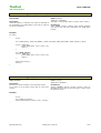
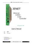
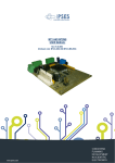
ThePod is a flexible USB device that offers a two-wire UART
interface at CMOS levels and a full-featured SPI master
interface.
It has been designed to provide a complete tool for in–system
programming and real-time debug of embedded systems
using microcontrollers, DSP or FPGAs.
SPI master
MOSI,
SCLK,
CS, CSAUX
MISO
USB
device
UART
Special provisions are available for SPI slave booting of
processors.
NRESET
Additional applications for specific families can be download
on the support web pages for ThePod.
NREQ/WAIT
2 GPIO
No external power supply is required, as ThePod draws its
power from the USB interface.
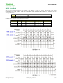
Connector pinout
OUT
OUT
OS support
Windows 2000/XP/Vista
USB interface
2.0 full-speed, USB-powered
Voltage levels
3.3V or 5V
TXD
1
2
RXD
IN
GND
3
4
SPI_MISO
IN
GND
5
6
SPI_CLK
OUT
Max SPI speed
3 Mbps
GND
7
8
SPI_CS
OUT
SPI modes
0
CPOL = 0, CPHA = 0
SPI_MOSI
9
10
NREQ
IN
1
CPOL = 0, CPHA = 1
GND
11
12
GND
2
CPOL = 1, CPHA = 0
3
CPOL = 1, CPHA = 1
OUT
SPI_CSAUX
13
14
GP0
I/O
I/O
GP1
15
16
NRESET
OUT
SPI word width
8, 16, 24, 32 bit
UART baud rate
2400........320k bps
to target
USB to host
SPI activity
Latest documentation, drivers and
application software at
www.zpeng.com/thepod
ZP Engineering srl
ThePod_UM_v100.doc
1/15
ThePod
User’s Manual
USB Debug Adapter
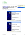
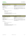
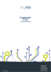
Installation
ThePod requires the installation of three drivers (channel A for SPI,
channel B for the serial port, and a virtual COM port driver).
Download
the
latest
drivers
from
ThePod
web
site
(www.zpeng.com/thepod) and unzip the relevant files in a known
location. In the following screenshots, the installation files are
available in C:\prj\thepod\ThePod ZP Drivers (02.00).
Then, follow these steps:
plug ThePod on any available USB port of your computer
follow the usual procedure for installing new hardware, as in these screenshots:
ZP Engineering srl
ThePod_UM_v100.doc
2/15
ThePod
User’s Manual
USB Debug Adapter
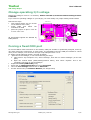
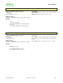
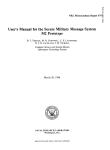
Please indicate the folder
where installation files have
been unzipped.
At the following question, click on “continue
anyway”
This completes the installation
procedure for ThePod Channel A.
ZP Engineering srl
ThePod_UM_v100.doc
3/15
ThePod
User’s Manual
USB Debug Adapter
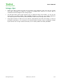
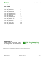
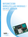
Continue to follow the install wizard for “ThePod Channel B” and then for
images below).
/ThePod Serial Port”(see
At this point installation is completed; you should be able to see the following:
ZP Engineering srl
ThePod_UM_v100.doc
4/15
ThePod
User’s Manual
USB Debug Adapter
SPI modes
One of the strongest features of ThePod is the ability to work in all four SPI modes. The usual
terminology for SPI modes, that was originated from Motorola data sheets, is referring to two
configuration bits:
CPOL
CPHA
SPI clock polarity
SPI sampling phase
0 = active HI, 1 = active LO
0 = sample then shift, 1 = shift then sample
leading to the following four allowed SPI modes:
SPI MODE
0
1
2
3
ZP Engineering srl
CPOL
0
0
1
1
CPHA
0
1
0
1
Shift on
Falling edge
Rising edge
Rising edge
Falling edge
Sample on
Rising edge
Falling edge
Falling edge
Rising edge
ThePod_UM_v100.doc
Idle CLK
LO
LO
HI
HI
5/15
ThePod
User’s Manual
USB Debug Adapter
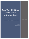
Change operating I/O voltage
Default I/O voltage is set at 3.3 V at factory. Please note that I/O with the default setting is NOT 5
V tolerant.
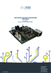
If you need 5 V operating voltages on your target, you must modify one jumper setting inside ThePod.
Follow these steps:
open ThePod (there are two screws
on the bottom of the case)
locate
JMP2
and
follow
the
indications on PCB
place the jumper on pins 1-2 for 5V
or on 2-3 for 3.3V.
USB socket
All input/output signals are affected by
JMP2 position.
Forcing a fixed COM port
As several USB-to-serial converters on the market, COM port number is dynamically assigned, and may
vary with consecutive connections. In some cases, it is desirable to force the COM port number to a fixed
value; as an example, Tera Term Pro can open only COM ports from 1 to 4.
To assign a fixed COM port number, proceed as follows:
Open the Device Manager, in one of the following two ways:
a. right-click on “My Computer” icon, select “manage”, then click on “Device Manager” (on the left
pane)
b. Open the Control Panel (Start/Settings/Control Panel), then select “System” and in the
“Hardware” tab click on “Device Manager”
Expand the Ports (COM & LPT) entry
Right-click on ThePod Serial Port and select Properties
Go to the Port Settings tab and click on Advanced…
Put the desired entry on COM Port Number (see image below)
ZP Engineering srl
ThePod_UM_v100.doc
6/15
ThePod
User’s Manual
USB Debug Adapter
Usage tips
Please note that to enable the serial port on ThePod, some application must open the DLL at least
once after connecting; all outputs on ThePod are disabled after power-up, to ensure that no
unwanted interaction happens with running targets.
The API base library offers 8-bit transfers only; to implement larger word widths, you can use the
block modes (see TPOD_WrBlk8, TPOD_RdWrBlk8 functions). In this way, your custom application
can easily implement 16-bit, 24-bit, 32-bit transfers in little-endian and big-endian modes.
Single byte transfers on USB are not very efficient, independently from SPI clock settings. In order to
get better performance, it is necessary to use block transfers functions (which encapsulate multiple
bytes transfers into a single ThePod command) such as TPOD_WrBlk8 and TPOD_RdWrBlk8.
ZP Engineering srl
ThePod_UM_v100.doc
7/15
ThePod
User’s Manual
USB Debug Adapter
API Reference
A complete API reference is provided for the development of custom applications using ThePod.
The following functions are available:
Init
Utility
GPIO
Manual CS/NRESET/NREQ
operations
SPI Read & Write
TPOD_Open()
TPOD_Close()
TPOD_Ver()
TPOD_ConfigGPIO()
TPOD_SetGPIO()
TPOD_GetGPIO()
TPOD_SetCS()
TPOD_SetCSAUX()
TPOD_SetNRESET()
TPOD_GetNREQ()
TPOD_Wr8()
TPOD_WrBlk8()
TPOD_RdWr8()
TPOD_RdWrBlk8()
int WINAPI TPOD_Open (int index, int spi_mode, int cs_sel, int lsb,
unsigned short clk_div)
Init function
Description:
Initialize the library. Must be called prior of any other
functions defined in this library.
It allows to defines:
SPI Mode (Mode 0, Mode 1, Mode 2, Mode 3)
Which pin used for CS (Main or Aux)
Byte order (LSB or MSB first)
SPI Clock (range from 91.5 Hz to 3 MHz)
Return (integer):
TPOD_OK = SUCCESS;
otherwise = FAIL (please refers to section “Error codes”);
Parameters:
Input: index (integer): defines which thePod interface
you want to use. Normally if you have only one thePod
connected to your host PC you must use index=0. If you
have more than one thePod connected to your host PC
please refers to section “Using multiple thePod interface”.
Input: spi_mode (integer): defines the SPI Mode you
want to use. The following values can be used:
#define
#define
#define
#define
TPOD_SPI_MODE_0
TPOD_SPI_MODE_1
TPOD_SPI_MODE_2
TPOD_SPI_MODE_3
0x40
0x41
0x42
0x43
Input: cs_sel (integer): defines the pin used for the CS
signal. The following values can be used:
#define TPOD_CS_MAIN
#define TPOD_CS_AUX
0x0
0x1
Input: lsb (integer): defines the byte order. The following
values can be used:
#define TPOD_MSB_FIRST
#define TPOD_LSB_FIRST
0x0
0x1
Input: clk_div (integer 16-bit): defines the SPI clock.
The values of clock is the result of the following formula:
SPI Clock = 12MHz / (( 1 + [clk_div]) * 2)
The following values are already defined in the header
file:
#define
#define
#define
#define
#define
#define
#define
#define
#define
//...
//...
//...
#define
TPOD_CLKDIV_6_MHZ
TPOD_CLKDIV_3_MHZ
TPOD_CLKDIV_2_MHZ
TPOD_CLKDIV_1_5_MHZ
TPOD_CLKDIV_1_2_MHZ
TPOD_CLKDIV_1_MHZ
TPOD_CLKDIV_800_KHZ
TPOD_CLKDIV_750_KHZ
TPOD_CLKDIV_650_KHZ
0x0000
0x0001
0x0002
0x0003
0x0004
0x0005
0x0006
0x0007
0x0008
TPOD_CLKDIV_91_5_HZ
0xFFFF
Example:
int main()
{
int ret;
ret = TPOD_Open(0, TPOD_SPI_MODE_3, TPOD_CS_MAIN, TPOD_MSB_FIRST, TPOD_CLKDIV_1_MHZ);
…
if (ret != TPOD_OK) {
printf("TPOD_Open - Error: %d\n", ret);
return 0;
}
ZP Engineering srl
ThePod_UM_v100.doc
8/15
ThePod
User’s Manual
USB Debug Adapter
int WINAPI TPOD_Close (int index)
Init function
Description:
Closes the library. It releases any resources allocated in
the initialization (see TPOD_Open) and must be called at
the end of operations.
Return (integer):
TPOD_OK = SUCCESS;
otherwise = FAIL (please refers to section “Error codes”);
Parameters:
Input: index (integer): defines which thePod interface
you want to use. For more information see TPOD_Open
function.
Example:
int main()
{
int ret;
ret = TPOD_Open(0, TPOD_SPI_MODE_3, TPOD_CS_MAIN, TPOD_MSB_FIRST, TPOD_CLKDIV_1_MHZ);
if (ret != TPOD_OK) {
printf("TPOD_Open - Error: %d\n", ret);
return 0;
}
ret = TPOD_Close(0);
if (ret != TPOD_OK) {
printf("TPOD_Close - Error: %d\n", ret);
return 0;
}
}
printf("\nBye bye\n");
return 0;
int WINAPI TPOD_Ver (char *version)
Utility function
Description:
Returns the version of library in the following format:
xx.yy where xx is the major version and yy is the minor
version.
Return (integer):
TPOD_OK = SUCCESS;
Parameters:
Output: version (string): Enough memory must be
allocated from the caller to store the library version string
formatted as above
Example:
…
…
int ret;
ret = TPOD_Ver(version);
printf("ThePod Library Version: %s\n", version);
ZP Engineering srl
ThePod_UM_v100.doc
9/15
ThePod
User’s Manual
USB Debug Adapter
int WINAPI TPOD_ConfigGPIO (int index, unsigned char gpio,
unsigned char mode)
GPIO function
Description:
Configures the selected custom GPIO pin as input or
output.
Return (integer):
TPOD_OK = SUCCESS;
otherwise = FAIL (please refers to section “Error codes”);
Input: gpio (byte): defines the GPIO pin. The following
values can be used:
#define TPOD_GPIO_0
0x0
#define TPOD_GPIO_1
0x1
Input: mode (byte): defines GPIO mode (input/output).
The following values can be used:
#define TPOD_GPIO_INPUT
0x0
#define TPOD_GPIO_OUTPUT
0x1
Parameters:
Input: index (integer): defines which thePod interface to
use. For more information, see TPOD_Open function.
Example:
int ret;
ret = TPOD_ConfigGPIO(0, TPOD_GPIO_0, TPOD_GPIO_OUTPUT);
ret = TPOD_ConfigGPIO(0, TPOD_GPIO_1, TPOD_GPIO_INPUT);
int WINAPI TPOD_SetGPIO (int index, unsigned char gpio,
unsigned char value)
GPIO function
Parameters:
Description:
Changes the specified custom GPIO pin level.
Input: index (integer): defines which thePod interface
you want to use. For more information see TPOD_Open
function.
Return (integer):
TPOD_OK = SUCCESS;
otherwise = FAIL (please refers to section “Error codes”);
Input: gpio (byte): defines the GPIO pin. Please see
TPOD_ConfigGPIO function.
Input: value (byte): defines pin level (hi/low). The
following values can be used:
#define TPOD_GPIO_LOW
#define TPOD_GPIO_HI
0x0
0x1
Example:
int ret;
ret = TPOD_ConfigGPIO(0, TPOD_GPIO_0, TPOD_GPIO_OUTPUT);
ret = TPOD_SetGPIO(0, TPOD_GPIO_0, TPOD_GPIO_HI);
int WINAPI TPOD_GetGPIO (int index, unsigned char gpio,
unsigned char *value)
GPIO function
Description:
Gets the specified custom GPIO pin level.
Return (integer):
TPOD_OK = SUCCESS;
otherwise = FAIL (please refers to section “Error codes”);
Parameters:
Input: index (integer): defines which thePod interface
you want to use. For more information see TPOD_Open
function.
Input: gpio (byte): defines the GPIO pin. Please see
TPOD_ConfigGPIO function.
Output: value (byte): it stores pin level (1=hi / 0=low)
Example:
…
int ret;
unsigned char value;
ret = TPOD_ConfigGPIO(0, TPOD_GPIO_1, TPOD_GPIO_INPUT);
ret = TPOD_GetGPIO(0, TPOD_GPIO_1, &value)
printf(“GPIO 1 Level: %d\n”, value);
ZP Engineering srl
ThePod_UM_v100.doc
10/15
ThePod
User’s Manual
USB Debug Adapter
int WINAPI TPOD_SetCS (int index, unsigned char value)
Manual CS/NRESET/NREQ operations
Description:
Changes CS main pin level.
Return (integer):
TPOD_OK = SUCCESS;
otherwise = FAIL (please refers to section “Error codes”);
Example:
Parameters:
Input: index (integer): defines which thePod interface
you want to use. For more information see TPOD_Open
function.
Input: value (byte): defines pin level (hi/low).
Note: when CS manual mode operation is the preferred
way to access to target device, remember to specify
TPOD_CS_MANUAL in the cs_mode parameter of read
and write SPI functions.
int ret;
unsigned char buff_out[2], buff_in[2];
buff_out[0] = 0x30;
buff_out[1] = 0x70;
ret = TPOD_SetCS(0, TPOD_GPIO_LOW);
ret = TPOD_RdWr8(0, buff_out, buff_in, 2, TPOD_CS_MANUAL);
ret = TPOD_SetCS(0, TPOD_GPIO_HI);
int WINAPI TPOD_SetCSAUX (int index, unsigned char value)
Manual CS/NRESET/NREQ operations
Description:
Changes CS auxiliary pin level.
Return (integer):
TPOD_OK = SUCCESS;
otherwise = FAIL (please refers to section “Error codes”);
Example:
Parameters:
Input: index (integer): defines which thePod interface
you want to use. For more information see TPOD_Open
function.
Input: value (byte): defines pin level (hi/low).
Note: when CS manual mode operation is the preferred
way to access to target device, remember to specify
TPOD_CS_MANUAL in the cs_mode parameter of read
and write SPI functions.
int ret;
unsigned char buff_out[2], buff_in[2];
buff_out[0] = 0x30;
buff_out[1] = 0x70;
ret = TPOD_SetCSAUX(0, TPOD_GPIO_LOW);
ret = TPOD_RdWr8(0, buff_out, buff_in, 2, TPOD_CS_MANUAL);
ret = TPOD_SetCSAUX(0, TPOD_GPIO_HI);
ZP Engineering srl
ThePod_UM_v100.doc
11/15
ThePod
User’s Manual
USB Debug Adapter
int WINAPI TPOD_SetNRESET (int index, unsigned char value)
Manual CS/NRESET/NREQ operations
Parameters:
Input: index (integer): defines which thePod interface
you want to use.
Input: value (byte): defines pin level (hi/low).
Description:
Changes NRESET pin level.
Return (integer):
TPOD_OK = SUCCESS;
otherwise = FAIL (please refers to section “Error codes”);
Example:
int ret;
…
// Perform a cycle reset
ret = TPOD_SetNRESET(0, TPOD_GPIO_LOW);
Sleep(10);
ret = TPOD_SetNRESET(0, TPOD_GPIO_HI);
int WINAPI TPOD_GetNREQ (int index, unsigned char *value)
Manual CS/NRESET/NREQ operations
Parameters:
Description:
Gets NREQ pin level.
Input: index (integer): defines which thePod interface
you want to use. For more information see TPOD_Open
function.
Return (integer):
TPOD_OK = SUCCESS;
otherwise = FAIL (please refers to section “Error codes”);
Output: value (byte): it stores pin level (1=hi / 0=low)
Example:
int ret;
unsigned char value;
ret = TPOD_GetNREQ(0, &value)
printf(“NREQ Level: %d\n”, value);
ZP Engineering srl
ThePod_UM_v100.doc
12/15
ThePod
User’s Manual
USB Debug Adapter
int WINAPI TPOD_Wr8 (int index, unsigned char *buff, int size,
char cs_mode)
SPI Read & Write Functions
Description:
Performs an SPI Write operation. This function performs
an USB write operation transfer for every single byte in
the specified buffer. If cs_mode is TPOD_CS_AUTO, for
every byte written the CS signal changes accordingly with
the SPI mode selected in the TPOD_Open function.
Return (integer):
TPOD_OK = SUCCESS;
otherwise = FAIL (please refers to section “Error codes”);
Example:
Parameters:
Input: index (integer): defines which thePod interface
you want to use.
Input: buff (array of byte/word/dword): contains bytes
to be sent to the device. NB: Don’t exceed 16 Kb buffer
size.
Input: size (integer): defines buffer size, always specified
in bytes.
Input: cs_mode (char): specifies CS mode. The following
values can be used:
#define TPOD_CS_AUTO
0x0
#define TPOD_CS_MANUAL
0x1
int ret;
unsigned char buff_out[2], buff_in[2];
buff_out[0] = 0x30;
buff_out[1] = 0x70;
ret = TPOD_Wr8(0, buff_out, 2, TPOD_CS_AUTO);
int WINAPI TPOD_WrBlk8 (int index, unsigned char *buff, int size,
char cs_mode)
SPI Read & Write Functions
Parameters:
Description:
Performs an SPI Write operation. This function performs a
single USB write operation transfer for the entire specified
buffer. If cs_mode is TPOD_CS_AUTO, the CS signal
changes accordingly with the SPI mode selected in the
TPOD_Open function only at begin and at end of the write
block operation.
Input: index (integer): defines which thePod interface
you want to use.
Input: buff (array of byte/word/dword): contains bytes
to be sent to the device. NB: Don’t exceed 16 Kb buffer
size.
Input: size (integer): defines buffer size, always specified
in bytes.
Input: cs_mode (char): specifies CS mode. The following
values can be used:
#define TPOD_CS_AUTO
0x0
#define TPOD_CS_MANUAL
0x1
Return (integer):
TPOD_OK = SUCCESS;
otherwise = FAIL (please refers to section “Error codes”);
Example:
int ret;
unsigned char buff_out[2], buff_in[2];
buff_out[0] = 0x30;
buff_out[1] = 0x70;
ret = TPOD_Wr8(0, buff_out, 2, TPOD_CS_AUTO);
ZP Engineering srl
ThePod_UM_v100.doc
13/15
ThePod
User’s Manual
USB Debug Adapter
int WINAPI TPOD_RdWr8 (int index, unsigned char *buff_out,
unsigned char *buff_in, int size, char cs_mode)
SPI Read & Write Functions
Parameters:
Description:
Performs an SPI Read/Write operation. This function
performs an USB read/write operation transfer for every
single byte in the specified buffer. If cs_mode is
TPOD_CS_ AUTO, the CS signal changes accordingly with
the SPI mode selected in the TPOD_Open function for
every byte of the specified buffer.
Input: index (integer): defines which thePod interface
you want to use.
Input: buff_out (array of byte/word/dword): contains
bytes to be sent to the device. NB: Don’t exceed 16 Kb
buffer size.
Output: buff_out (array of byte/word/dword): It stores
bytes to be received from the device. NB: Don’t exceed
16 Kb buffer size.
Input: size (integer): defines buffer size, always specified
in bytes.
Input: cs_mode (char): specifies CS mode. The following
values can be used:
#define TPOD_CS_AUTO
0x0
#define TPOD_CS_MANUAL
0x1
Return (integer):
TPOD_OK = SUCCESS;
otherwise = FAIL (please refers to section “Error codes”);
Example:
int ret;
unsigned char buff_out[2], buff_in[2];
buff_out[0] = 0x30;
buff_out[1] = 0x70;
ret = TPOD_RdWr8(0, buff_out, buff_in, 2, TPOD_CS_AUTO);
int WINAPI TPOD_RdWrBlk8 (int index, unsigned char *buff_out,
unsigned char *buff_in, int size, char cs_mode)
SPI Read & Write Functions
Description:
Performs an SPI Read/Write operation. This function
performs a single USB read/write operation transfer for
the entire buffer. If cs_mode is TPOD_CS_AUTO, the CS
signal changes accordingly with SPI mode selected in
TPOD_Open function only at begin and end of the
read/write block operation.
Return (integer):
TPOD_OK = SUCCESS;
otherwise = FAIL (please refers to section “Error codes”);
Example:
Parameters:
Input: index (integer): defines which thePod interface
you want to use.
Input: buff_out (array of byte/word/dword): contains
bytes to be sent to the device. NB: Don’t exceed 16 Kb
buffer size.
Output: buff_out (array of byte/word/dword): It stores
bytes to be received from the device. NB: Don’t exceed
16 Kb buffer size.
Input: size (integer): defines buffer size, always specified
in bytes.
Input: cs_mode (char): specifies CS mode. The following
values can be used:
#define TPOD_CS_AUTO
0x0
#define TPOD_CS_MANUAL
0x1
int ret;
unsigned char buff_out[2], buff_in[2];
buff_out[0] = 0x30;
buff_out[1] = 0x70;
ret = TPOD_RdWrBlk8(0, buff_out, buff_in, 2, TPOD_CS_AUTO);
ZP Engineering srl
ThePod_UM_v100.doc
14/15
ThePod
User’s Manual
USB Debug Adapter
Error Codes
#define
#define
#define
#define
#define
#define
#define
#define
#define
#define
#define
#define
#define
#define
#define
#define
#define
#define
#define
#define
TPOD_OK
TPOD_ERROR_OPEN
TPOD_ERROR_GETDEV
TPOD_ERROR_CLOSE
TPOD_ERROR_SYNC
TPOD_ERROR_RDBLOCK
TPOD_ERROR_WRBLOCK
TPOD_ERROR_CONFIGSPI
TPOD_ERROR_SETDATABITS
TPOD_ERROR_GETDATABITS
TPOD_ERROR_SETCLKDIV
TPOD_ERROR_FLUSH
TPOD_ERROR_SETBITMODE
TPOD_ERROR_CONFIG_GPIO
TPOD_ERROR_SET_GPIO
TPOD_ERROR_GET_GPIO
TPOD_ERROR_WR8
TPOD_ERROR_WRBLK8
TPOD_ERROR_RDWR8
TPOD_ERROR_RDWRBLK8
#define TPOD_ALREADY_OPEN
#define TPOD_ERROR_MEMORY
#define TPOD_ERROR_TIMEOUT
0
-1
-2
-3
-4
-5
-6
-7
-8
-9
-10
-11
-12
-13
-14
-15
-16
-17
-18
-19
0xF0
0xF1
0xF2
ZP Engineering srl
via Ardito Desio, 60 – 00131 ROME - ITALY
tel. +39.06.41230392, fax +39.06.41293033
www.zpeng.com
(C) ZP Engineering srl, 2007. Specifications and appearance are subject to variations without notice.
ZP Engineering srl
ThePod_UM_v100.doc
15/15