1
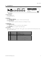
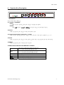
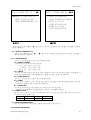
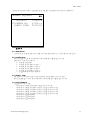
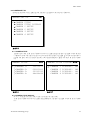
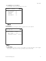
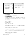
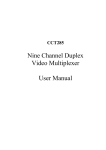
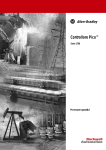
ARC-19504
Four Channels Duplex
Video Multiplexer
User’s Manual
ARC-19504
CONTENTS
2000/9/27
V1.0
040046
1. Introduction………………………………………………………………….2
2. Specification…….……………………………………………………………3
3. Installation……………………………………………………………………4
4. Function Key Description…………………………………………………5
5. Operation Mode……………………………………………………………6
6. Recording and Playback…………………………………………………….7
7. Alarm Function………………………………………………………………8
8. Menu Set Up…………………….…………………………………………...9
ArcVision Technology Corp.
1
ARC-19504
1.
Introduction
1.1
1.2
1.3
1.4
1.5
1.4
1.5
1.6
1.7
1.8
1.8
1.9
1.10
1.11
1.12
1.13
1.14
1.15
1.16
1.17
The user’s manual is suited for two versions, the color version and the B/W version.
Automatically detect NTSC/PAL for color version.
Automatically detect EIA/CCIR for B/W version.
Video signals with AGC (Auto Gain Control) function.
Video loss detection with adjustable sensitivity.
Adopt E.A.L. (Erase Asynchronous Line) technique.
Quad display refresh rate of color version is 60 fields/sec for NTSC, 50 fields/sec for PAL.
Quad display refresh rate of B/W version is 60 fields/sec for EIA, 50 fields/sec for CCIR.
Full duplex for recording and displaying.
The image on the monitor doesn’t scroll when Channels switching.
Skip unconnected channels at sequence mode.
Supports freeze function for quad display at normal and playback modes.
Supports freeze function for full-image display at playback mode.
Supports four-channel external alarm trigger.
Register alarm events up to 60 records.
Supports synchronous mode and a synchronous mode for recording image.
Supports field and frame modes for recording and playback.
Display date, time, camera titles.
Supports user-friendly set-up menu.
The color version supports build-in color-bar generator for adjusting monitors.
ArcVision Technology Corp.
2
ARC-19504
2.
Specification
Refresh rate (Color Version)
NTSC : 60 fields/sec, PAL : 50 fields/sec
Refresh rate (B/W Version)
EIA : 60 fields/sec, CCIR : 50 fields/sec
Resolution (H×V)
NTSC : 860×525, PAL : 860×625 (CCIR-601 standard)
Video input port
BNC×4 cameras + BNC×1 VCR play inputs
Video output port
BNC×1 Monitor out, BNC×1 VCR Record out
Video output signal
1 Vp-p / 75Ω CVBS out
Video output format
Full/Quad/Freeze/Auto switch programmable
Title generator
Up to 8 characters each channel
Timer generator
Built-in real time clock
Dimension
218(W)× 202(D)× 44(H) mm
Power source
DC 12V ±10﹪
Power consumption
7.5W(max), 600mA@12V Recommend adapter: DC 12V/1A
ArcVision Technology Corp.
3
ARC-19504
3.
Installation
VIDEO IN
DC IN
ALARM
I/O
ALARM
MONITOR
OUT
ALARM
I/O
ALARM
VCR
IN
VCR
OUT
4
3
2
1
1.ALARM IN-4
2.ALARM IN-3
3.GND
4.ALARM IN-2
5.ALARM IN-1
6.VCR SYNC IN
7.RELAY OUT-COM
8.RELAY OUT-N.O.
9.RELAY OUT-N.C.
Back Panel
3.1 Power Supply
DC 12V ±10%, 600mA
recommend DC 12V, 1A。
3.2 VIDEO IN
3.2.1 CAMERA VIDEO IN
Four cameras BNC inputs. BNC #1 to 4 are for camera video in only.
3.2.2 VCR VIDEO IN
BNC “VCR IN” is connected exclusively from VCR “VIDEO OUT” only.
3.3 VIDEO OUT
3.3.1 MONITOR OUT
BNC “MONITOR OUT” is connected to monitor “VIDEO IN”.
3.3.2 VCR OUT
BNC “VCR OUT” is connected to the VCR “VCR IN”.
3.4 ALARM I/O
There is a DB9 connector on the left side of the back panel, which is connected to the external alarm sensors and
time lapse VCR trigger input.
1 ALARM IN-4
External alarm input 4
2 ALARM IN-3
External alarm input 3
3 GND
Ground
4 ALARM IN-2
External alarm input 2
5 ALARM IN-1
External alarm input 1
6 VCR SYNC IN
VCR trigger
7 RELAY OUT-COM
Relay output COM terminal
8 RELAY OUT-N.O.
Relay output normal open terminal
9 RELAY OUT-N.C.
Relay output close terminal
DB9 PIN CONFIGURATION
ArcVision Technology Corp.
4
ARC-19504
4.
Function Key Description
Front Panel
From left front panel button key
4.1 <QUAD> / <FREEZE>
QUAD:
Under normal or playback mode, press this key to display quad images.
FREEZE:
Under quad display of normal or playback mode, press this key to enter freeze function.
4.2 AUTO
Under normal mode, press this key to enter auto sequence mode.
4.3 Camera selection keys camera #1, 2, 3 and 4
Under normal or playback mode, press this key to select full-view of the camera channels #1, 2, 3, or 4.
4.4 PLAY
Under normal mode, press this key to enter playback mode, return to normal mode press this button again.
4.5 MENU
Under normal mode, press to enter menu set up mode.
4.6 MENU FUNCTION KEYS AT MENU SET UP MODE
↑/←
┼
Move cursor to above item during menu operation.
Move to the left item during editing procedure.
Move cursor to next item during menu operation.
Move to the right item during editing procedure.
Next value.
─
EXIT
ENTER
Previous value.
Exit the menu or editing procedure.
Enter to sub-menu or editing procedure.
↓/→
ArcVision Technology Corp.
5
ARC-19504
5.
Operation Mode
There are four operational modes on the multiplexer.
Mode
Normal
Auto
Sequence
Playback
Menu set up
Description
After power on the multiplexer goes into normal mode automatically.
Press camera selection key to view full-image and press <QUAD> key to view quad-images.
This mode supports freeze function under quad-view:
1. Under quad-view of the normal mode, presses <FREEZE> key to enter freeze function.
While the LED indicator of freeze begins to flash user can freeze or release any channel you
selected.
2. Press camera channel selection key to select a camera channel that you want to freeze.
While the camera channel selection LED goes to “ON” the image of the related camera is
frozen.
3. In order to release frozen image(s) press the camera selection key again to select a camera
which image has been frozen.
While the camera LED indicator goes to “OFF” the image is released and begins to refresh.
4. User can freeze and release image(s) for every camera channel independently.
5. To quit form freeze mode, press <FREEZE> key again to return to quad-view of normal mode.
The freeze LED indicator stops flashing and goes to permanent “ON”.
Under normal mode, press <AUTO> key to enter sequence mode.
Under this mode, the monitor displays image according to user’s definition of channel sequences and
dwell time.
Refer to page 11, “8.2 CHANNEL SEQUENCE” for more details.
To exit sequence mode:
1. Press camera channel selection key or <QUAD> key to exit auto sequence mode and enter
normal mode.
2. Press <PLAY> key to enter playback mode.
3. Press <MENU> key to enter menu set up mode。
In normal or sequence mode, press <PLAY> key to enter the playback mode.
Under this mode user can playback VCR that was recorded by this multiplexer.
It is impossible to view images if another multiplexer recorded the images.
Support quad-image and full-image view.
Support freeze function for quad-image and full-image:
1. The frozen function for quad-view is same with normal mode.
2. Under full-view of the selected camera channel, press camera channel selection key again to
freeze the image. The LED indicator of selected channel begins to flash.
3. Press <QUAD> key or camera channel selection keys will release camera channel to quadimage and or full-image of selected camera channel.
Press <PLAY> key again to exit playback mode and goes back to normal mode.
Under normal or sequence mode, press <MENU> key to enter menu set up mode.
Refer page 9, “8. Menu set up” for more details.
ArcVision Technology Corp.
6
ARC-19504
6.
Recording and Playback
The multiplexer is full duplex. The “full duplex” means once the multiplexer’s power is turned “ON” the
BNC “VCR OUT” sends video images continually to VCR1 “VIDEO IN” for recording purpose, and BNC “VCR IN” can
accept video images sends from VCR2 for playback viewing.
6.1 RECORD
The time-lapse VCR recorder can record video images frame by frame or field by field. The multiplexer can also be
set in accordance with the setting of the time-lapse to output the video images from BNC “VCR OUT”.
(a) TO RECORD USING EXTERNALTRIGGER SIGNAL FROM TIME-LAPSE VCR:
This feature is for time-lapse VCR recorder only. The time-lapse VCR recorder generates a trigger signal from
“VCR trigger” to signal multiplexers when is the time to switch channels.
We recommend using this feature if user’s VCR recorder supports this feature.
The acceptable trigger signal is a falling edge (negative) trigger.
(b) RECORD BY SETTING RECORDING TIME:
The multiplexer can calculate channel-switching time by setting recording time at menu set up.
The record time of the multiplexer must match with the recording time setting of the VCR recorder if use
time-lapse VCR recorder.
The multiplexer supports 2 hours (2H), 24 hours (24H), 24hours real motion (24RH), 48 hours (48H), 72
hours (72H), 120 hours (120H), 168 hours (168H), 240 hours (240H),480 hours (480H), 720 hours (720H).
Notice: User must set it to “2H” if the VCR is not a time-lapse one.
6.2 PLAYBACK
To playback the tapes user can choose using frame mode (frame by frame) or field mode (field by field).
Notice:
If playback a tape which was recorded by field mode under frame mode (frame by frame). It will cause
missing images of some channels. Please set playback mode to field. Please refer to page 13, “8.4 VCR SET
UP” for more details.
ArcVision Technology Corp.
7
ARC-19504
7.
Alarm
7.1 ALARM TYPES
There are three kinds of alarm events:
(a) Power-on time and date sequence.
(b) Video signals loss.
(c) External alarm trigger.
7.2 RESPONSE TYPES OF ALARM
There are three types of responses:
(a) Buzzer turns on.
(b) Relay turns on.
(c) Trigger by alarm inputs.
7.3 THE ALARM EVENTS PROCESS
(a) When the power on event accrues, the relay and buzzer will keep “OFF” state but the same event could be
written into the alarm list. This feature can be used to check whether the multiplexer has ever been turned off or
not.
(b) When video loss occurs, the relay and buzzer will be turned “ON” if they are enabled in menu set up. The events
also could be written to the alarm list.
User can set the sensitivity to check video loss according to the applications.
(c) The multiplexer supports 4 channels alarm inputs.
User can set the property for every alarm sensor. Refer to page 14, “8.5.1.1 ALARM #1, 2, 3, and 4 CONFIG”
for more details.
ArcVision Technology Corp.
8
ARC-19504
8.
Menu Set Up
8.0 THE STRUCTURE OF MENU
MAIN MENU
z
)zOSD
& TIMER SET UP
zCHANNEL SEQUENCE
zCAMERA SET UP
zVCR SET UP
zALARM PROCESSOR
zOTHERS
Figure 8-1
The main menu shows in Figure 8-1. Take the main menu for example to introduce the structure of menus.
(a) The title of menu:
Located at the top left side of the first line “MAIN MENU”.
(b) Levels indicator:
Located at the top right side of the first line.
The symbol ”●” indicates the level numbers of the menu.
One symbol ”●” indicates the menu is level 1, two symbols ”●●” indicates the menu is level 2…and
so on.
(c) Item indicator (Cursor):
The symbol “)” indicates which item will be available for setting.
(d) The type field of the item:
Located at the right of the item indicator.
There are three kinds of item indicators:
”●” :Denotes there a sub-menu and need to press <ENTER> to active next menu.
”》” :Denotes that there is no sub-menu, but user need to press <ENTER> key to edit items.
No symbol:Denotes user can press <-> <+> key to set value to previous or next, decrease or
increase numbers.
(e) Item:
Take Figure 8-1 for example, ”OSD & TIMER SET UP” is the first item selected by the “Item indicator”.
8.1 OSD & TIMER SET UP
ArcVision Technology Corp.
9
ARC-19504
OSD & TIMER SET UP
zz
) z DATE & TIME SET UP
TEXT COLOR:COLOR 1
TEXT TRANSPARENCY 00
Figure 8-2
DATE & TIMER SET UP zzz
) DATE DISPLAY:ON
DATE FORMAT:YY-MM-DD
》DATE 00-01-01
TIME DISPLAY:ON
》TIME 00:00:00
POSITION:BOTTOM
Figure 8-3
In the main menu uses <↑> or <↓> key to select “OSD & TIMER SET UP”, and press <ENTER> to enter the
menu of Figure 8-2.
8.1.1 DATE & TIMER SET UP
In the menu of Figure 8-2 uses <↑> or <↓> key to select “DATE & TIME SET UP” item, press <ENTER> to
enter the sub-menu of Figure 8-3.
8.1.1.1 DATE DISPLAY
Set “ON” to display date, “OFF” to turn off the date display.
8.1.1.2 DATE FORMAT
The date format can be one of the following:
YY-MM-DD (year-month-day)
MM-DD-YY (month-day-year)
DD-MM-YY (day-month-year)
8.1.1.3 DATE
Set date according to date format. In the menu of Figure 8-3, select “DATE” item and press <ENTER> key to
enter the editing procedure. After finishing press <EXIT> to return to the menu of Figure 8-3.
8.1.1.4 TIME DISPLAY
Set “ON” to display time, “OFF” to turn off the time display.
8.1.1.5 TIME
In the menu of Figure 8-3, select “TIME” item and press <ENTER> to enter the editing procedure. After time
setting press <EXIT> to return to the menu of Figure 8-3.
8.1.1.6 POSITION
Set the position to display time and date. The position can be one of following:
LEFT TOP, TOP, RIGHT TOP, LEFT BOTTOM, BOTTOM and RIGHT BOTTOM.
8.1.2 TEXT COLOR
The text color can be set to one of the following value for color version, and for B/W version can be set to
“COLOR 0” and “COLOR 1” only.
COLOR 0 Black
COLOR 2 Green
COLOR 1 White
COLOR 3 Blue
8.1.3 TEXT TRANSPARENCY
There are thirteen levels of transparency adjustment that can be set from 00 to 12.
8.2 CHANNEL SEQUENCE
ArcVision Technology Corp.
10
ARC-19504
In the main menu select “CHANNEL SEQUENCE” and press <ENTER> to enter the menu of Figure 8-4.
zz
CHANNEL SEQUENCE
SEQUENCE:
) 》CAMERA NO:
》DWELL TIME:
12345678
Q1234--22222222
Figure 8-4
8.2.1 SEQUENCE
In auto sequence mode the order of switching is as following sequence #1, 2…and 8 and switch back to #1.
8.2.2 CAMERA NO
Press <ENTER> to enter the edit procedure. After editing press <EXIT> key to escape.
There are six values that can be set:
Q:to display quad-images
1:to display the full-image of camera 1
2:to display the full-image of camera 2
3:to display the full-image of camera 3
4:to display the full-image of camera 4
-:to skip the sequence to next sequence
8.2.3 DWELL TIME
The numbers of the time seconds of the auto sequence that the images stay for how long.
Press <ENTER> key to active the edit procedure. After editing press <EXIT> key to escape.
8.2.4 FOR EXAMPLE
Take Figure 8-4 for example:
<Sequence 1> Display quad-images, and keep about 3 seconds.
<Sequence 2> Display full-image of camera 1 and keep about 3 seconds.
<Sequence 3> Display full-image of camera 2 and keep about 3 seconds.
<Sequence 4> Display full-image of camera 3 and keep about 3 seconds.
<Sequence 5> Display full-image of camera 4 and keep about 3 seconds.
<Sequence 6> Skip the sequence.
<Sequence 7> Skip the sequence.
<Sequence 8> Skip the sequence.
ArcVision Technology Corp.
11
ARC-19504
8.3 CAMERA SET UP
In the main menu select “CAMERA SET UP”, and press <ENTER> to enter the menu of Figure 8-5.
CAMERA SET UP
) zCAMERA
z CAMERA
z CAMERA
z CAMERA
z CAMERA
z CAMERA
zz
TITLE
TITLE DISPLAY
1 SETUP
2 SETUP
3 SETUP
4 SETUP
Figure 8-5
8.3.1 CAMERA TITLE
Edit the camera titles. In the menu of Figure 8-5 select “CAMERA TITLE” and press <ENTER> to enter the menu
of Figure 8-6. Select the camera which you want to edit its title, and press <ENTER> key to enter edit procedure to
edit the title. Every title can contain 8 characters. After finish editing press <EXIT> to return to the menu of Figure
8-6.
CAMERA TITLE
) 》CAMERA
》CAMERA
》CAMERA
》CAMERA
1:
2:
3:
4:
Figure 8-6
zzz
11111111
22222222
33333333
44444444
CAMERA TITLE DISPLAY zzz
)
CAMERA
CAMERA
CAMERA
CAMERA
1
2
3
4
DISPLAY:
DISPLAY:
DISPLAY:
DISPLAY:
ON
ON
ON
ON
Figure 8-7
8.3.2 CAMERA TITLE DISPLAY
Set “ON” to display the camera titles, “OFF” can’t display the camera titles.
In the menu of Figure 8-5 select “CAMERA TITLE DISPLAY”, and press <ENTER> to enter the menu of Figure
8-7。
ArcVision Technology Corp.
12
ARC-19504
8.3.3 CAMERA #1, 2, 3 and 4 SET UP
Set the brightness, contrast, chroma and sharpness for each camera.
zzz
CAMERA 1 SETUP
) BRIGHTNESS
CONTRAST
CHROMA
SHARPNESS
25
32
32
10
Figure 8-8
8.4 VCR SET UP
In the main menu select ”VCR SET UP”, and press <ENTER> to enter the menu of Figure 8-9.
VCR SET UP
zz
) REC
MODE : FIELD
REC TIME :
2H
PLAYBACK MODE : FIELD
Figure 8-9
8.4.1 REC MODE
The VCR output from the BNC “VCR OUT” of the multiplexer is for VCR recording purpose can be set “FIELD”
(field by field) or “FRAME” (frame by frame). The setting must match with VCR setting.
ArcVision Technology Corp.
13
ARC-19504
8.4.2 REC TIME
The multiplexer supports synchronous and asynchronous mode for VCR.
Synchronous mode:
To operate in this mode, the signals “TRIGGER OUT” and “GND” from VCR must connected to the
multiplexer. We recommend using synchronous mode if your VCR supports this function.
Asynchronous mode:
The multiplexer supports 2 hours (2H), 24 hours (24H), 24hours real motion (24RH), 48 hours (48H),
72 hours (72H), 120 hours (120H), 168 hours (168H), 240 hours (240H), 480 hours (480H),
720 hours (720H). User must set it to “2H” if the VCR is not a time lapse one.
8.4.3 PLAYBACK MODE
Set the playback mode for playback. User can choose “FRAME” or “FIELD”.
Notice:
If play VCR in playback mode using “FRAME” mode and some image of camera are lost, please set the
playback mode to “FIELD” and try again.
8.5 ALARM PROCESSOR
In the main menu select “ALARM PROCESSOR”, and press <ENTER> to enter the menu of figure 8-10.
ALARM PROCESSOR
)zALARM CONFIGURE
》SHOW ALARM LIST
》CLEAR ALARM LIST
Figure 8-10
zz
ALARM CONFIGURE
zzz
)z ALARM 1 CONFIGURE
z ALARM 2 CONFIGURE
z ALARM 3 CONFIGURE
z ALARM 4 CONFIGURE
z VIDEO LOSS CONFIGURE
ALARM DURATION 01 MIN
ALARM LIST
NO
ALARM FULL SCREEN YES
ANY KEY TO STOP
YES
Figure 8-11
8.5.1 ALARM CONFIG
In the menu of Figure 8-10 select “ALARM CONFIG”, and press <ENTER> to enter the menu of Figure 8-11.
8.5.1.1 ALARM #1, 2, 3, and 4 CONFIG
The multiplexer supports four-channel alarm inputs.
In the menu of Figure 8-11 select “ALARM 1 CONFIG”, and press <ENTER> to enter the menu of Figure 8-12.
8.5.1.1.1 SENSOR ENABLE
Set “YES” to enable the sensor detection.
Set “NO” to ignore the sensor.
ArcVision Technology Corp.
14
ARC-19504
ALARM 1 CONFIGURE
)
zzzz
SENSOR ENABLE
YES
SENSOR TYPE
NO
SENSOR SENSITIVITY 01
BUZZER ENABLE
YES
ALARM OUTPUT
YES
Figure 8-12
VIDEO LOSS CONFIGUREzzzz
) DETECTION
ENABLE
SENSITIVITY
BUZZER ENABLE
ALARM OUTPUT
YES
20
YES
YES
Figure 8-13
8.5.1.1.2 SENSOR TYPE
Set “NC” for normal-close sensor, “NO” for normal-open sensor.
8.5.1.1.3 SENSOR SENSITIVITY
For different sensors the sensitivity are not all the same. The setting value of sensor sensitivity is a time
constant. When a changing of the alarm signal occurs, the multiplexer will detect the signal continually among
the time constant. If the alarm sign have a changing and keep the signal level over the time constant, the alarm
signal is valid otherwise the signal is noise. The unit of sensor sensitivity is 1/60 sec for NTSC or EIA and
1/50 sec for PAL or CCIR.
8.5.1.1.4 BUZZER ENABLE
Set “YES” to turn the internal buzzer on if a valid alarm accrue.
Set “NO” to keep the buzzer mute.
8.5.1.1.5 ALARM OUTPUT
Set “YES” to turn the relay on if a valid alarm accrue.
Set “NO” to keep relay to the current state.
8.5.1.2 VIDEO LOSS CONFIG
In the manual of Figure 8-11, select “VIDEO LOSS CONFIG”, press <ENTER> key to enter next menu of
Figure 8-13
.
8.5.1.2.1 DETECTION ENABLE
Set “YES” to detect video loss, “NO” to disable video loss detection.
8.5.1.2.2 SENSOR SENSITIVITY
Set the checking sensitivity for video loss. The setting value of sensitivity is a time constant. When video
signal disappear, the multiplexer will detect the signal continually among the time constant. If the video sign
lost over the time constant, the video loss is valid otherwise it will be a noise. The unit of sensor sensitivity is
1/60 sec for NTSC or EIA and 1/50 sec for PAL or CCIR.
8.5.1.2.3 BUZZER ENABLE
Set “YES” to turn the internal buzzer on if a valid video loss occurs.
Set “NO” to keep the buzzer mute.
ArcVision Technology Corp.
15
ARC-19504
8.5.1.2.4 ALARM OUTPUT
Set “YES” to turn the relay on if a valid video loss occurs.
Set “NO” to keep relay to the current state.
8.5.1.3 ALARM DURATION
The alarm output will keep for a time interval called alarm duration if a valid alarm occurs. The unit of alarm
duration is second.
8.5.1.4 ALARM LIST
Set “YES” to save the alarm events as a record if a valid alarm occurs. If set “NO”, the alarm events will not be
saved.
8.5.1.5 ALARM FULL SCREEN
Set “YES” to switch to full-view of the related camera from quad-view if a valid alarm occurs. It will take effect
under normal and sequence modes. Setting “NO” will keep current viewing.
8.5.1.6 ANY KEY TO STOP
User can press any key to stop the alarm output when alarm output accrue if set “YES”. Setting “NO” the alarm
output will keep over the alarm duration and can’t stop by user.
8.5.2 SHOW ALARM LIST
At the menu of Figure 8-10, select “SHOW ALARM LIST”, and press <ENTER> key to show alarm list.
ALARM LIST
CH1 A 24-01-00
CH2 V 24-01-00
ON P 24-01-00
P01
17:01:22
17:01:22
17:01:22
a. The first and the second fields standard for alarm
events.
CH1 A:The first channel alarm input.
where 'A' is denotes alarm
CH2 V:The second channel video loss.
where 'V' is denotes video loss.
ON P:Power-up.
where 'P' is denotes power.
b. The 3'rd field is the date of event accruing.
The date format is the same as setting by 7.1.1.2.
c. The last field is the time of event accruing.
d. User cna use <↓> or <↑> key to turn next page or
previous page.
e. Press <EXIT> to escape the alarm list.
The alarm list is shown as Figure 8-14.
Figure 8-14
8.5.3 CLEAR ALARM LIST
In the menu of Figure 8-10, select “CLEAR ALARM LIST”, and press <ENTER> to clear alarm list.
8.6 OTHERS
In the main menu, select “OTHERS”, and press <ENTER> to enter the menu of Figure 8-15.
ArcVision Technology Corp.
16
ARC-19504
OTHERS
zz
) 》COLOR BAR
》BLUE FIELD
VIDEO SYSTEM
AUTO
》LOAD FACTORY DEFAULT
》LOAD USER SETTING
》SAVE USER SETTING
Figure 8-15
8.6.1 COLOR BAR (FOR COLOR VERSION ONLY)
Display color bar in order to adjust the monitor.
8.6.2 BLUE FIELD (FOR COLOR VERSION ONLY)
Display blue field in order to adjust the monitor.
8.6.3 VIDEO SYSTEM
Three are three kinds of parameters for video system setting:
For color version:
AUTO:Auto detects NTSC or PAL, if the “channel 1” camera connected.
NTSC:Set video system as NTSC。
PAL:Set video system as PAL。
For B/W version:
AUTO:Auto detects EIA or CCIR, if the “channel 1” camera connected.
EIA:Set video system as EIA。
CCIR:Set video system as CCIR。
8.6.4 LOAD FACTORY DEFAULT
Load parameters of factory default.
8.6.5 LOAD USER SETTING
Load the parameters saved by user using “SAVE USER SETTING”. If user never saved the parameters, it will be
the same as factory default.
8.6.6 SAVE USER SETTING
Save the parameters of menu set up.
ArcVision Technology Corp.
17