Transcript
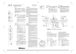
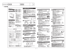
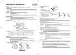
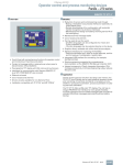
User’s Manual No.99MAG020B3 Series No.7・547 Upright Gage (Dial Type/Digital Type) 7.Attaching and Removing Limit Hand (Dial Type) Separate the limit hand 〈Attachment〉 Limit hand before attaching it. Introduction Clamp screw B 〈Attachment〉 Clamping plate A : Insert clamp bracket in the A Export Control Compliance The goods, technologies or software described herein may be subject to National or International, or Japanese Export Controls. To export directly or indirectly such matter without due approval from the appropriate authorities may therefore be a breach of export control regulations and the law. 1.Safety Precautions ・Indicates a potentially hazardous situation which, if not avoided, may result in minor or moderate injury or property damage. Caution 2.On Various Types of Notes dovetail groove Clamp bracket Bezel Take care not to injure yourself when separating the limit A:Attach the limit hand to the bezel. Caution hand or handling the B:Push the limit hand all the separated parts. way until it clicks. a : To remove the limit hand push it up in the direction of the arrow. ・An important note is a type of precaution, which if neglected could result in a loss of data, decreased accuracy or instrument malfunction/failure. ・A note emphasizes or supplements important points of the main text. 3.Operating Environment I M P O R TAN T ・Use the gage in an environment with a temperature of 0 to 40℃ and a relative humidity of 30 to 70%. ・Avoid sudden changes in temperature. Condensation may negatively affect the performance of the gage. ・Use the gage in a place with minimal exposure to dust, oil and oil mist. ・Use the gage in a place out of direct sunlight. *The appearance of a gage varies with the model. 〈Attachment Dial Type〉 A:Lift the spindle and fit the forked end of the lifting lever to the spindle stop under the spacer. B : Fit the lifting lever into the dovetail groove and fix in position by pushing down in the direction of the arrow. 〈Removal Dial Type〉 a:Push the finger rest up in the direction of the arrow and remove the lifting lever. 〈Attachment Digital Type〉 A:Loosen the screw in the indicator body. B:Lift the spindle and fit the forked end of the lifting lever to the spindle stop under the spacer. C:Fit the groove in the lifting lever bracket under the screw head which can then be tightened. 〈Removal Digital Type〉 a:Loosen the screw and remove the lifting lever. B:Fix with clamp screw. A a N o t e Take note that the clamp may loosen or fall off under vibration. A B 9.Attaching and Removing the Lifting Lever I M P O R TAN T ・An important note provides information essential to the completion of a task. 4.Part Names 〈Removal〉 B Please read this user’s manual before using the gage. Store this manual in an easily accessible place after reading it. NOTE 8.Attaching Bezel Clamp (Dial Type) a Dovetail groove B C a A 10.Instructions for Use Type A Type B 5.Specifications Code No. Measuring Range (Individual Indicator) 0 to 20 mm (0 to 10 mm) 0 to 20 mm (0 to 10 mm) 0 to 35 mm (0 to 10 mm) 0 to 30 mm (0 to 1 mm) 0 to 1” (0 to 1”) 7050 7051 7052 7053 7056 547-034 547-035 547-054 547-055 0 to 1.2”/0 to 30 mm (0 to 5”/0 to 12 mm) 0 to 1.2”/0 to 30 mm (0 to 5”/0 to 12 mm) 0 to 30 mm (0 to 12 mm) 0 to 30 mm (0 to 12 mm) Accuracy ±15 μm Indicator 2046S 0.01 mm Contact Point S3 carbide 6 flat Graduation contact point ±15 μm 2046S 0.01 mm ±15 μm 2046SLB 0.01 mm S3 carbide ±5 μm 2109SLB-10 0.001 mm S3 carbide ±.002” 2416S .001” S3 carbide ±.001” 543-272B (ID-C1012EB) .0005” /0.01 mm S3 carbide 543-252B (ID-C112EB) 543-270B (ID-C1012B) 543-250B (ID-C112B) .00005” /0.001 mm S3 carbide ±.00015” ±20 μm ±3 μm contact point contact point contact point contact point contact point contact point 0.01 mm S3 carbide 0.001 mm S3 carbide contact point contact point Diameter Measuring Table Flatness Stroke Remarks 40 mm 3 μm 20 mm With lifting lever 40 mm 3 μm 20 mm With lifting lever 40 mm 3 μm 20 mm 40 mm 3 μm 20 mm 1.57”DIA 3 μm .8”/20 mm 1.57”DIA /40 mm 3 μm .8”/20 mm 1.57”DIA /40 mm 3 μm .8”/20 mm 40 mm 3 μm 20 mm 40 mm 3 μm 20 mm (Frame: Type A) (Frame: Type A) With lifting lever (Frame: Type B) With lifting lever (Frame: Type B) With lifting lever (Frame: Type A) With lifting lever (Frame: Type B) With release (Frame: Type B) With lifting lever (Frame: Type B) With release (Frame: Type B) ・Limit hand is not included in No.7056. 《Reference》Optional Accessories 80 Large measuring table:No.902190,50 Ceramic measuring table:No.903526,Limit hand:No.21AAB155,Clamp bracket:No.21AAB161 Clamp screw:No.21AAB162(Except No.7056) , No.101214(For No.7056) , Clamping plate:No21AAB163 NOTE ・Workpieces with a height exceeding the measurement range or a depth exceeding 45 mm cannot be measured. ・Do not apply the load of 30N or more onto the measuring table when the measuring table clamp is tightened. ・The indicator of No.7052 and No.7053 can be moved up and down within a range of 20 mm by adjusting the position of the stem clamp. 6.Notes on Use I M P O R TAN T ・Do not suddenly activate the spindle or apply an excessive horizontal load. ・Be sure to check the accuracy of gage if it has been dropped or otherwise subjected to shock. ・If the contact point of the indicator repeatedly contacts the measuring table, the measuring table might be damaged. If a bulge results from damaging the measuring table, the measuring table must be ground again. Ask Mitutoyo for repairs in this case. Even if a bulge is not caused, the zero position of the indicated value might become incorrect due to the damage.To use the dial gage, move the tip of the contact point away from the position of the measuring table damage by: loosening the portion for fixing the indicator in place and rotating the indicator for models that have the type A frame, or rotating the measuring table for models that have the type B frame. ・Ensure that the spindle and hands operate smoothly. Also check that the digital display is working normally. ・Ensure that the contact point and screw are not loose. ・Regularly check and adjust the reference point when using the gage in a place subject to temperature variation. ・This spacer is there to aid the movement of the lifting lever and should not be removed. 1) Wipe the contact point and surface of the measuring table to remove any dust. If there is damage to the measuring table, refer to section 6 and request repairs, or move the center of the contact point away from the position of the damage for use. 2) Adjust the height of the measuring table and securely fix the measuring table clamp. 3) Set the reference point. Specify the measuring table or master gage (such as the gauge block) as the reference surface. Specifying the master gage as the reference surface is recommended to avoid damage to the measuring table. Set the measuring table or master gage (gauge block, etc.) as the reference surface. Use the lifting lever and release to move the contact point up and down several times. Check that the graduation value when the contact point touches the reference surface is stable. Dial type gage ·········· Adjust the long hand so that it points to the zero graduation mark by rotating the bezel. Digital type gage ······ Press the ZERO/ABS button. (This is useful when the master gage is set as the reference surface because the measurement value can be automatically read by using the PRESET function. See the Digimatic Indicator User’s Manual for details of the PRESET function.) Use the lifting lever and release again to check that the reference point has not shifted. 4) Measure the workpiece. Use the lifting lever or release to slowly bring the contact point into contact with the workpiece. Repeat this several times and read the value after checking that the graduation value is stable. N O T E ・If a master gage was used to set zero, the measured dimension is the sum of the indicated value and the master gage dimension.(This does not apply when using the PRESET function.) ・Slowly return the contact point to the original position when adjusting the reference, measuring a workpiece, or after completing measurement. Repeatedly dropping the contact point and causing it to contact the measuring table might damage the measuring table, master gage, or workpiece. 《Reference》Tolerance judgment It is possible to set the gage to indicate whether the measured dimension is within tolerance as follows: Dial type gage ····· Set the tolerance by attaching a limit hand to the positions of the upper and lower limit values. Judge whether the workpiece dimensions are within the tolerance range by determining whether the long hand points within the allowable range indicated by the limit hands when the workpiece is measured. Be aware of the value indicated by the short hand to avoid misreading one rotation of the long hand. Digital type gage · Set the tolerance by using the tolerance setting function. Judge whether the workpiece dimensions are within the tolerance range via the symbol that is displayed when the workpiece is measured. (See the Digimatic Indicator User’s Manual for details of the tolerance setting function.) 11.Maintenance and Repairs I M P O R TAN T ・When carrying the gage, be sure to hold the frame so that you do not drop the unit. ・Remove dirt or dust from the sliding surface of the spindle using a dry cloth or a cloth on which a neutral detergent has been applied. ・Remove dirt or dust on the bezel or digital display surface using a soft dry cloth or a cloth on which a neutral detergent has been applied. ・If you will not use the upright gage for a long period of time, apply a little anti-corrosive oil to the top of the measuring table and the bottom of the frame before putting the gage into storage ・The performance deterioration of this gage differs greatly depending on the usage conditions. Customers are therefore advised to establish in-house standards that take into consideration the actual usage frequency, environment, and method, and perform regular maintenance checks on the gage based on these standards. ・Mitutoyo does not guarantee the performance of this gage if repair or disassembly has been performed by other than Mitutoyo.