1
重 要
IMPORTANT • Do not subject the instrument to blows or knocks.
1000
注 記
・落下などの急激なショックを与えたり、過度の力
を加えないでください。
・分解、改造しないでください。
・尖ったもの
(ドライバ−・ボ−ルペンの先など)
で
キ−操作をしないでください。
・直射日光のあたる場所、極端に熱い所・寒い所で
の使用、保管は避けてください。
・空気の希薄な場所や高圧の場所では、材料の劣化
などによる故障の恐れがあります。
・湿気やほこりの多い場所での保管、水や油が直接
かかるような使用は避けてください。
・電気ペン等の高電圧機器を使用した場合、電子部
品が破壊される場合があります。また電気的ノイ
ズの大きい場所での使用は誤動作の恐れがありま
す。
・ダイヤルゲ−ジスタンドなどに確実に固定し、振
動のない場所でご使用ください。
・スピンドルに対し垂直な方向の荷重や、ねじれが
かかるような使用は避けてください。
・お手入れの際は、乾いた柔らかい布・綿棒などを
そのまま、もしくは希釈した中性洗剤に浸してご
利用ください。有機溶剤
(シンナ−・ベンジン)
を
使用すると変形や故障の原因となります。
・スピンドルの汚れは動作不良の原因となります。
アルコ−ルを含ませた布などできれいに汚れを拭
き取り、粘性の低い油を小量含ませた布で軽く拭
いてご使用ください。
温度変動が大きい場所では、構成部品や固定治具類
の熱膨張のため測長原点と設定原点の間にズレが生
じます。できるかぎり温度変動の少ないところでご
使用ください。また、本機を異なる温度の場所に移
動して使用する際は、十分温度に慣らしてからご使
用ください。
Do not drop it or apply excessive force to it.
• Do not disassemble or modify the instrument.
• Do not press the key with a pointed object (such
as screwdriver or ballpoint pen).
• Do not use or store the instrument under direct
sunlight, or in an excessively hot or cold place.
• Be alert for instrument failure due to material
deterioration if it is used in an environment with
low or high atmospheric pressure.
• Do not use the instrument if it has been splashed
with water or oil. Do not store it in a damp or dusty
environment.
• Do not use a high-voltage equipment, such as an
electric marking pen, near the instrument.
Electronic parts may be damaged. Be alert for
instrument malfunction if it is used in the vicinity of
electric noise.
• Secure the instrument with a fixture such as a dial
gage stand in a vibration-free environment.
• Do not subject the spindle to a vertical load or
torsion.
• Use a soft cloth or a cotton swab that is dry or
soaked in diluted neutral detergent to wipe stains
from the instrument panel. Do not use organic
solvent such as thinner and benzene. The
instrument panel may be deformed or may
malfunction.
• Wipe the spindle clean with a cloth soaked in
alcohol, then gently wipe it with a cloth soaked with
a small quantity of low viscosity oil. Contaminated
spindles do not have smooth movement.
NOTE
Use the instrument in a temperature-controlled room
that has minimum temperature fluctuation. Allow a
sufficient time for the instrument to thermally stabilize
if it is moved to an environment with a different
temperature. Be alert for an origin point error
between the origin of the gage setup and that of the
instrument caused by thermal expansion of the
component parts and the fixtures under a significant
temperature fluctuation.
2
19
3/4"
9.6
3/8"
9
6.35
1/4"
5
in/mm
+/–
5
6
平裏蓋の場合
Flat back
7.6
ON/OFF
2
17
16
in/mm
+/–
ON/OFF
PRESET TOL.
12
13
14
15
φ 54
2.13"
50.95
2"
44.2
1.74"
7
・測定子結合部ねじ
Contact Point equipped
M2.5×0.45 thread
ON/OFF
PRESET TOL.
0
φ8-0.009
ZERO/ABS
+/–
60.5
φ
2 3/8"
ZERO/ABS
3
With lug
10
4
11
20.05
.79"
Cautions on use
Observe the following precautions to avoid equipment failure
and malfunction
8
10.6
14.2
9/16"
以下の行為、状況は本機の故障・誤動作の原因となりますの
でお気を付けください。
27.6
10.9"
1
6.5
"
1/4
ご使用上の注意
20
ISO/JIS type
7.6
0.3"
6.35
1/4"
SR44
10.5
13/32"
耳金付きの場合
with lug
49.6
1.95"
警 告
• Liquid crystal display and silver oxide battery
are used in this product. When disposing,
conform to the ordinances or regulations of
WARNING
respective local governments.
• Liquid crystal display part contains irritating
substance. Should the liquid content
accidentally come in contact with the eye or
skin, cleanse with clean, flowing water. If the
substance get in the mouth, immediately rinse
inside the mouth, swallow plenty of water, vomit,
then consult a physician.
1
• Do not disassemble, short-circuit, charge, heat the
battery to 100°C and over, or throw the battery
into fire; otherwise the content may leak to come
WARNING in contact with the eye, or cause heating or
explosion.
• Should the content accidentally come into contact
with the eye or skin, or get into the mouth, rinse
with water immediately and consult a physician.
Should it attach to the clothes, wash it with water.
• For disposing or storing battery, cover the
positive(+) and negative(–) terminals with a piece
of insulating tape to prevent contact with other
metals.
• To store, avoid direct sunlight, high temperature
and high humidity.
54.4
SR44
・分解、ショ−ト、充電、100℃以上の加熱、火の
中へ投入などしないでください。内容物が漏れ、
目に入ったり、発熱、破裂の原因となります。
・万一、内容物が目や口に入ったり皮膚に付着した
場合は直ちに水で洗い流し、医師に相談してくだ
さい。衣服に付着した場合は水で洗い流してくだ
さい。
・電池を廃棄する場合および保存する場合は、絶縁
テ−プで電池の+−極を包むなどの処理をして他
の金属が電池と接しないようにしてください。
・直射日光、高温、高湿の場所を避けて保管してくだ
さい。
16.5
Warning on battery
警 告
21.2
電池に関する注意
;
7.3
To take full advantage of this gage, read this manual
thoroughly before using it. After reading, retain this manual
for future reference. Specifications of the Digimatic
Indicator and the information in this manual are subject to
change without notice.
Warranty: In the event that the Mitutoyo Digimatic
Indicator should prove defective in workmanship or
material, within one year from the date of original purchase
for use, it will be repaired or replaced, at our option, free
of charge upon its prepaid return to us. Please contact
your Mitutoyo office.
46.5
ご使用になる前にこの取扱説明書をよくお読みいただき、
各機能を十分にご理解の上、正しくお取り扱いください
ますようお願いいたします。また、本書はお読みになっ
た後も大切に保管してください。本機の仕様及び本書の
内容は将来予告なしに変更することがあります。万一弊
社の製造販売に起因する不具合がお買上より一年以内に
発生した場合、無償修理いたしますのでお求めの販売店、
営業所までご連絡ください。
・本製品には液晶および酸化銀電池が使用され
ています。それぞれの廃棄にあたっては、各
地方自治体の条例または規制などに従ってく
ださい。
・液晶の内部には刺激性物質が含まれています。
万一液状の内容物が誤って目や皮膚などに付
着した場合、清浄な流水で洗浄してください。
口に入った場合は、直ちに口内を洗浄し大量
の水を与えて吐き出させた後医師に相談して
ください。
φ60.5
Introduction
.5
;;
はじめに
Warning on Disposal
廃棄に関する注意
φ6
SR44
No. 99MAH007B
SERIES No. 543
φ54
ID-C
デジマチックインジケータ
Digimatic Indicator
Flat back
0
φ9.52 -0.03
3/8"DIA
・Contact Point equipped
AGD type No.4-48 UNF thread
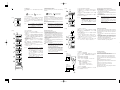
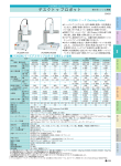
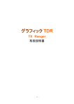
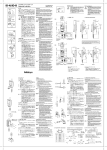
1. 各部名称・寸法
1. Parts Names and Dimensions
・単位なき寸法値はmmを示します。
・ はAmerican Gage Design (AGD)を表す記号で、
ANSI規格AGD Group2の要求する寸法部を示す。(サ
フィックスにE, Tの付くタイプについて適用)
①キャップ ②耳金 ③平裏蓋 ④出力コネクタ
(ゴムキャッ
プ付)⑤ステム ⑥スピンドル ⑦測定子 ⑧電池キャップ
⑨LCD ⑩レバ−取付けネジ ⑪レリ−ズ取付け穴
• Dimensions without unit are in mm.
means American Gage Design (AGD) specification.
•
The section whose dimensions shall meet the ANSI
specifications AGD Group2 is identified with this symbol.
(Applicable to the type suffixed with E or T.)
1Cap 2Lug 3Flat back 4Output connector (with
rubber cap) 5Stem 6Spindle 7Contact point 8Battery
cap 9LCD 0Lever mounting screw
ARelease mounting hole
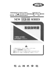
2. スイッチの名称と機能
2. Names and Functions of Keys
⑫ON/OFF
: 電源のON/OFF
⑬ZERO/ABS : ABSモ−ド・INCモ−ドの切り換え
INCモ−ドでのゼロセット
⑭PRESET
: プリセット値の登録、呼び出し
⑮TOL.
: 公差設定値の登録、公差判定モ−ドへ
の切り換え
⑯+/−
: カウント方向の設定
公差判定モ−ドでは、拡大表示への切
り換え
⑰in/mm
: inch表示、mm表示の切り換え
(輸出仕様のみ)
BON/OFF
: For setting the power ON/OFF
CZERO/ABS : Switches between ABS and INC
modes. In INC mode, it resets the
display.
DPRESET
: For setting and recalling the preset
value
ETOL.
: For setting tolerance limits/tolerancing
mode
F +/−
: For switching the counting direction,
for magnified indication in tolerance
and
judgement mode.
Gin/mm
: For switching the unit between inches
and mm
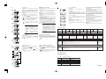
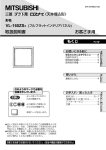
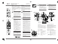
3. セットアップ
3
3.1 電池の交換
本機は、酸化銀電池(SR44)
1個を使用します。
・電池キャップの溝に硬貨などを当て反時計方向
(矢印の
方向)
に回してはずします。電池キャップとシ−ルは紛
失しやすいので作業の際の扱いに十分ご注意ください。
・古い電池を取り出します
(未使用の電池と混ざらないよ
。
[3.1] う正しく廃棄してください)
・新しいSR44の "+" の表示が外から見えるようにセッ
トします。
・シ−ルがはみ出さないよう気を付けて電池キャップを
時計方向に回して取付けます。
・電池をセットしなおすと原点情報がクリアされ[-----]と
表示されますので、適当な位置でPRESETキ−を操作
して原点の設定をしてください。
("5.2プリセット値の
設定" 参照)
(A)
330°
(B)
[3.2]
+ 44
SR
in/mm
+/–
ZERO/ABS
ON/OFF
PRESET TOL.
重 要
・上記の操作を行なっても原点設定ができない
場合、SR44をセットし直してください。
・三ヶ月以上本機をご使用にならない場合、電
池の液漏れによる機器の破損の恐れがありま
すので電池を取り外し別々に保管してくださ
い。
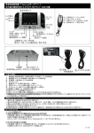
3.2 表示部の角度調整
表示部は、初期位置
(A)
から時計回りに330°
(B)
まで回転
します。
重 要
A, Bにストッパが入っていますが、これを越
えて回すと故障の原因となります。表示部を
引き抜いたり押し込んだりすると故障の原因
になります。
3.3 レリ−ズ
(#540774/別売)取付け
[3.3] レリ−ズ穴のねじ⑪
(M2.6)
を#0の十字ドライバ−で外し
レリ−ズをねじ込みます。
重 要
φ8(9.52)+0.02
+0.005
[3.4]
レリ−ズを強く引張ったり、叩いたりすると
ねじ山が欠落することがあります。レリ−ズ
以外のものを差し込んだり、過剰に力がかか
ると故障する恐れがあります。
[3.5]
3. Setup
3.1 Battery Replacement
Use a silver oxide battery (SR44).
• Remove the battery cap by turning it counterclockwise
(arrow direction) with a coin set in the groove. Do not
lose the battery cap and seal.
• Remove used battery.
• Set a new SR44 battery with the positive (+) side up.
• Secure the battery cap by turning it clockwise. Be careful
not to allow the seal to protrude.
• Replacing battery clears the origin information and [----] appears in the indicator. Set the origin again by using
the PRESET key ("5.2 Setting of Preset Value").
IMPORTANT • Should the origin setting fail, reset the SR44
battery.
• Remove the battery from the instrument if it
will not be used for more than three months.
The instrument may be damaged by battery
leakage.
b
a
注 記
・スピンドルが基準面と被測定面に対して垂直
になるように固定してください。軸線
(スピ
ンドル)
が基準面に垂直でない場合、測定値
に誤差が加算されます。
→例えば、基準面から軸線の傾斜角度ϕの時
の測定値12mmあたりの誤差δ は
ϕ =1°:δ=0.002 mm, ϕ =2°:δ=0.007 mm,
ϕ =3°:δ=0.016 mmとなります。
・治具などに取付ける際は、φ8G7
(+0.005∼
+0.02)
程度の嵌合部を持つすり割り付きの
ホルダ−にてステムを固定する方法をお薦め
します。
3.5 Mounting of Lifting Lever
[optional #902011(ISO) or #902794(AGD)]
Lever a and spindle hook b are packed together in a
lever assembly.
• Rotate the cap counterclockwise to remove it from the
instrument. Hold the spindle with a pliers by protecting
it with rags from being damaged, remove the screw
(M2.5(ISO) or #4-48UNF(AGD)) at the top of the spindle,
and screw in a hook.
• Loosen the lever mounting screw on the side of the
instrument and hook the lever on the hook.
3.6 測定子の交換
弊社ダイヤルゲ−ジ用オプションの各種特殊測定子・継
ぎ足しロッドがご利用頂けます。
・スピンドルが回らない様に、スピンドルをウェスなど
を介してプライヤで固定し、別のプライヤで測定子を
はさんで回して、測定子の取り外し・取付けを行なっ
てください。
3.6 Replacement of Contact Point
Various types of contact points and extension rods are
optionally available.
• Hold the spindle with pliers protecting it with rags, hold
the contact point with another pliers, and turn to remove
or mount it.
[3.6]
4
4. デ−タ出力
4. Data Output
M-SPCケ−ブル
(別売)
を用いてデジマチックミニプロセッ
サDP-1HS等のデ−タ処理装置に本機を接続することによ
り、測定値の転送や集計、記録等の処理を行なうことが
可能です。
・マイナスドライバ−等で出力コネクタ−のキャップを
取り外し、ケ−ブルを奥までしっかりと差し込んでく
ださい。
(外したキャップは小袋等に包み、紛失しない
よう保管してください。)
Vital SPC data is available by connecting the instrument
to a Digimatic Miniprocessor DP-1HS and other data
processor with an optional cable.
• Remove the cap of output connector using a slottedscrewdriver and insert the cable fully to the end. (Put
the removed cap in a small bag and store in safe place.)
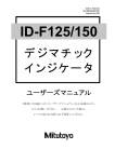
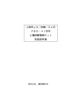
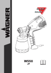
4.1 出力コネクタ
4.3 Timing Chart
4.2 出力デ−タフォ−マット
*1: Hold the REQ signal in Low state until CK is output.
Be sure to return it to High before the final CK (52th
bit) is output.
3.2 Adjustment of Display Unit Angle
The display unit rotates 330° (B) clockwise from the initial
position (A).
IMPORTANT • Do not rotate the display unit beyond the
stoppers at positions A and B. Caution, risk
of instrument failure.
• Do not pull or push the display unit. Caution,
risk of instrument failure.
3.3 Mounting of Release (#540774/optional)
Remove screwA(M2.6) of the release hole with #0 Philips
screwdriver and screw the release in.
IMPORTANT • Jerking or knocking the release may cause
the thread to be chipped off.
• Do not insert other than the release to the
hole or applying excessive force. Caution,
risk of instrument failure.
NOTE
• Set up the instrument with the spindle
perpendicular to the reference plane or the
measured surface. If the spindle axis is not
perpendicular to the reference plane
(measured surface), measurement errors will
result.
→ If the spindle axis is inclined ϕ from the
perpendicular line to the reference plane,
measurement error δ will be as follows for
the measured length of 12 mm:
ϕ = 1° : δ = 0.002 mm
ϕ = 2° : δ = 0.007 mm
ϕ = 3° : δ = 0.016 mm
• If the instrument is to be secured with a
fixture, fix it by the stem in a slotted hole of
approx. φ8G7 (+0.005 to +0.02) or φ9.52
(+0.005 to +0.02).
IMPORTANT • Use rag to protect the spindle during the
above work to avoid instrument failure. The
spindle does not move smoothly if damaged.
• Different contact point results in different
external dimensions, measuring force, and
limitation of measuring direction.
• Contact point error such as perpendicularity
of a flat contact point, run-out of roller point,
etc. adds to the measurement error.
重 要
[4.1]
上記作業の際スピンドルの固定を行なわない
と、故障する恐れがあります。またスピンド
ルを傷つけてしまうと動作不良の恐れがあり
ます。測定子の変更に伴い、外観寸法・測定
力の変化、測定方向の制限が生じる場合があ
ります。また測定精度に測定子の器差
(フラッ
ト測定子の直角度、ロ−ラ−測定子の芯振れ
など)が累積します。
4.3 タイミングチャ−ト
3.4 Securing the Instrument
3.4 スタンド、治具への取付け
Secure the instrument with a fixture such as a dial gage
本機はステムまたは耳金をダイヤルゲ−ジスタンド
(別売) stand by the stem or lug.
等に固定してお使いください。
IMPORTANT Avoid fixing the stem directly using a lock
重 要
screw. If fixed under a clamping torque of
止めネジなどでステムを直接締め付けて固定
300N • cm and over, the spindle may not move
する方法はできるだけ避けてください。300N・
smoothly.
cm以上の締め付けトルクで固定した場合、作
動不良が生じる恐れがあります。
3.5 レバ−
(#902011/別売)取付け
レバ−Assyには、レバ− a とストップねじ b が同梱さ
れています。
・本機のキャップを反時計方向に回転させ外し、スピン
ドルを傷つけない様に、ウェスなどを介してプライヤ
で固定します。
・スピンドル上端のねじ(M2.5)を取り外してストップねじ
を取付けます。
・本機側面のレバ−取付けねじをゆるめ、レバ−をストッ
プねじに掛けながら取付けます。
*1 : REQはCKが出力されるまでLowを保持してください。
また、最終のCK(52 bitめ)が出力される前にHighに
戻してください。
1
注 記
5
Signal
I/O
1.
Pin♯
GND
ー
2.*1
DATA
O
3.*1
CK
O
4.
N.C
ー
5.*2
REQ
I
*1
*2
REQ
CMOS
デ−タ出力を利用する際は、デ−タ処理装置
の取扱説明書をよくお読みになって正しくご
使用ください。本機のスピンドル作動時に出
力要求
(REQ)
を受けた場合やインターバルの
短かい連続したREQを受けた場合、データ出
力できないことがあります。
[4.2]
1000pF
NOTE
• Read the manual of the data processing
device thoroughly before outputting data for
proper operation.
• Data output may be disabled if an output
request (REQ) is received while the spindle
is in motion or if REQ are made at short
intervals during a continuous data output.
*1
REQ
DATA
CK
1.55V
1000kΩ 10kΩ
4.2 Output Data Format
小数点 Decimal point
X.X.X.X.X.X
2(0100)
d1 d2 d3 d4 d5 d6 d7 d8 d9 d10 d11 d12 d13
3(1100)
MSD
LSD
4(0010)
5(1010)
全て"F"(1111) 符号 Sign
測定値
単位/Unit
All "F"
0(0000) mm
+ : 0(0000) Measurements
1(1000) inch
− : 8(0001)
[4.3]
DATA
or CK
4.1 Output Connector
T1
T2 T3 T4
1bit → 2bit → ∼ 52bit
10ms<T1<30ms
0.09ms≦T2≦0.11ms
0.13ms≦T3≦0.15ms
0.53ms≦T4≦0.55ms
5
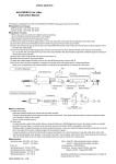
5. 操作方法
5. Operating Procedure
以下の説明図では、キ−の押し方を次の二通りに区別し
ます。
Two ways of pressing key are used in the following
illustration:
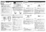
5.3 プリセット値の呼び出しと原点設定
この操作の前にカウント方向が正しく設定されているこ
とを確認します。そうでない場合、カウント方向を正し
く設定してください。
① [PRESET]キ−を押すと表示部右上に
「P」
サインが点滅
します。
② スピンドルを持ち上げ、測定子を基準にしたい位置に
セットします。
③ [PRESET]キ−を押します。
[5.3]
PRESET
1
P
短く押す。(2秒未満)
長く押す。(2秒以上)
5.1 カウント方向の設定
[+/−]キ−により、スピンドルが押し上げられると表示
値がプラスにカウントするか
(NORMALモ−ド)
、マイナ
スにカウントするか
(REVERSEモ−ド)
の設定が行なえま
す。REVERSEモ−ドでは、表示の右上に
「REV」
サインが
表示されます。
[ 5.1]
mm
+/−
注 記
REV
mm
Press short
(under 2 sec)
[+/−]キ−を押すと、カウント方向が切り換
わると同時に、表示値の符号
(±)
も換わります。
プリセット値の呼び出しなどの操作の前に、カ
ウント方向の設定を行なってください。
Press and hold
(2 sec or more)
5.1 Setting of Counting Direction
Pressing [+/−] key selects NORMAL mode where the
indicator value is counted up or REVERSE mode where
the indicator value is counted down when the spindle is
pushed up.
“REV” sign appears to the upper right hand corner of the
indicator when in reverse mode.
NOTE
mm
2
Reference
gage
基準ゲージ
NOTE
注 記
P
mm
PRESET
3
Pressing the [+/−] key selects the counting
direction, simultaneously changing the the sign
(±) of indicated value. Always set the counting
direction before recalling a preset value.
P
mm
PRESET
2
P
mm
PRESET
3
P
mm
PRESET
4
注 記
P
mm
twice
2回
PRESET
P
mm
PRESET
5
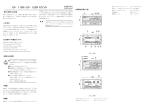
・電池投入直後には左の一番下
( )
内の様な表
示となりますので、一度[PRESET]キ−を短
く押しプリセットモ−ドにしてください。
・設定した値は電源をOFFにしても保持されま
す。ただし、電池が消耗したり、交換した時
には、プリセット値がクリアされますので再
設定してください。
・プリセットを途中で中断したい時は、[ZERO
/ABS]キ−を押すと、プリセットモ−ドが
解除されABSモ−ドに戻ります。
12.000
5.4 ABSモ−ドとINCモ−ド
本機には、プリセットで設定した値を原点とした絶対測
定用のABSモ−ドと比較測定用のINCモ−ドの二つの測定
モ−ドがあります。
① 電池の交換後を含めてプリセットの直後は、必ずABS
モードになります。
② ABSモ−ド時に[ZERO/ABS]キ−を押すと、INCモ−
ドになり、表示の左上に
「INC」
サインが表示され、INC
座標でZEROセットされます。INCモ−ドでの[ZERO/
ABS]キ−は、ゼロセットキ−となります。
③ INCモ−ド時に[ZERO/ABS]キ−を長く押すと、ABS
モ−ドになります。(
「INC」
サインが消えます。)
1
mm
ZERO/ABS
2
1 The instrument is in ABS mode upon completion of
presetting.
2 Pressing [ZERO/ABS] key in ABS mode switches the
mode to INC mode, sign “INC” starts blinking in the
upper left corner of the indicator, and the instrument is
ZERO set by pressing [ZERO/ABS] key.
3 Holding down [ZERO/ABS] key during INC mode
switches to ABS mode. Sign “INC” goes off.
mm
NOTE
• Upon battery replacement, the indication
appears as shown on the bottom to the left.
Press [PRESET] key short to set the
instrument in presetting mode.
• Set value will be retained if the power is OFF.
If the battery is worn out or replaced, preset
value is cleared and the value must be reset.
• To interrupt the presetting, press [ZERO/
ABS] key. Preset mode is canceled and the
system returns to ABS mode.
3
mm
[5.5]
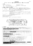
5.5 公差設定
(1)
ABSモ−ドの時の設定値
ABSモ−ドでの公差設定値は、基準となるゲ−ジの寸法
をプリセット値とし、許容範囲を絶対寸法で設定してく
ださい。
基準ゲージ
Reference gage
10
P
基準ゲージ
Reference gage
0.2
mm
上限値
Upper limit
6
上限値
Upper limit
下限値
Lower limit
PRESET
下限値
Lower limit
ー0.2
0
mm
電池交換直後
Upon battery replacement
5.4 ABS Mode and INC Mode
The instrument has two measurement modes; ABS mode
for absolute measurement with reference to the origin set
through presetting; and INC mode for comparative
measurement.
ZERO/ABS
mm
P
• Before setting the origin, fix the instrument
firmly to the stand, etc. and always have the
spindle slightly pushed in.
• The set origin position will be retained
together with the preset value even if the
power is turned OFF.
INC
10.2
PRESET
1
9.8
[ 5.2]
5.2 Setting of Preset Value
[Example] Presetting of 12.000 mm
1 Press [PRESET] key short. “P” sign starts blinking in
the upper right corner of the indicator.
2 Holding the [PRESET] key changes the digit to be set.
Release the key when a desired digit starts blinking.
3 Press [PRESET] key in repetition until a desired figure
appears in the indicator. The sign changes from + to and the figure from 0 → 1 → 2…→ 9.
4 Repeat procedures 2 and 3 to set the figures of the
following digit.
5 Hold [PRESET] key until the figure stops blinking and
sign “P” starts blinking.
6 Press [PRESET] key, and when sign “P” goes out,
presetting is completed.
・原点の設定は、本機をスタンドなどにしっか
りと固定し、必ずスピンドルを少し押し込ん
だ状態で行なってください。
・設定した原点位置は、電源をOFFにしてもプ
リセット値とともに測定原点として保持され
ます。
mm
[5.4]
5.2 プリセット値の設定
[例]
12.000 mmをプリセットする場合
① [PRESET]キ−を短く押すと表示部右上に
「P」
サインが
点滅します。
② [PRESET]キ−を長く押すと置数する桁を順に移動でき
ます。置数したい桁が点滅しはじめるまで[PRESET]キ
−を押し続け、置数する桁が点滅表示を開始した時に
[PRESET]キ−を一旦離します。
③ 希望の数字が表示されるまで[PRESET]キ−を繰り返し
短く押します。
符号は+→−、数字は0→1→2…→9と切り換わり
ます。
④ ②、③を繰り返し、以下の桁の数字を設定します。
⑤ 数字の点滅が消え「P」サインが点滅しはじめるまで
[PRESET]キ−を長く押します。
⑥ [PRESET]キ−を押し、
「P」
サインが消えるとプリセッ
トが完了します。
5.3 Calling of Preset Value and Origin Setting
First, check that the counting direction is correctly set. If
not, set it correctly.
1 Press [PRESET] key. Sign “P” starts blinking in the
upper right corner of the indicator.
2 Lift the spindle up, insert a reference gage and set the
contact point on it.
3 Press [PRESET] key. The indicator is ready to count
from the preset value.
上限値=基準値+上限の許容値
下限値=基準値+下限の許容値
(ただし、プリセット値=基準ゲ−ジの寸法とする)
〔例〕基準ゲ−ジ寸法=10.000 mm
基準値に対する許容値=±0.200 mm
の時の、上下限値の設定。
上限値=10.000+0.200=10.200(mm)
下限値=10.000+(−0.200)
=9.800(mm)
(2)
INCモ−ド時の設定値
INCモ−ドでの公差設定値は、基準となるゲ−ジの寸法を
0とした許容値としてください。
5.5 Setting of Tolerance
(1) Set value in ABS mode
In ABS mode, preset a reference dimension, and then set
tolerance values with the absolute dimension.
Upper limit = reference value + upper tolerance value
Lower limit = reference value + lower tolerance value
(where the reference value = reference gage dimension)
[Example]
Reference gage dimension = 10.000 mm
For setting the upper and lower tolerance values of ±0.200
mm
Upper limit = 10.000 + 0.200 = 10.200 (mm)
Lower limit = 10.000 + (–0.200) = 9.800 (mm)
(2) Set value in INC mode
Set tolerance limit in INC mode by setting the reference
gage dimension as zero (0).
[ 5.6]
TOL.
1
mm
TOL.
2
mm
TOL.
3
mm
TOL.
4
mm
TOL.
5
mm
TOL.
6
5.6 公差設定の方法
〔例〕上限値を10.200 mm、下限値を9.800 mmに設定する
場合。
」
サインが点滅しま
① [TOL.]キ−を押すと表示部上に
「
」
サイン表示中には上限公差を置数します。
す。
「
② 置数したい桁が点滅しはじめるまで[TOL.]キ−を押し
続けます。
③ 希望の数字が表示されるまで[TOL.]キ−を繰り返し短
く押します。
④ ②、③を繰り返し、以下の桁の数字を設定します。
」
サインが点滅しはじめるまで
⑤ 数字の点滅が消え
「
[TOL.]キ−を押し続けます。
」サインの点滅している時に、[TOL.]キ−を押し
⑥「
「
」
サインから
「
」
サインの点滅に切り換えます。
「
」
サイン表示中は、下限公差を置数します。
以下の操作は、②、③と同様の手順で行なってくださ
い。
」サインが点滅している時に、[TOL.]キ−を押し
⑦「
」
サインの点滅が消えると設定が完了し公差判定モ
「
−ドとなります。
注 記
・設定した公差値は電源をOFFにしても保持さ
れます。また、公差判定モ−ドの状態で電源
をOFFにした場合は、電源をONにした時、
公差判定モ−ドが再設定されます。ただし、
電池が消耗したり、交換したときには、公差
設定値がクリアされますので再設定してくだ
さい。
・公差設定モ−ドで[ZERO/ABS]キ−を押すと、
公差設定モ−ドが解除されABSモ−ドに戻り
ます。
5.6 Method of Tolerance Limit Setting
[Example]
For setting the upper limit to 10.200 mm and the lower
limit to 9.800 mm
• Set tolerance limit value will be retained if
the power is OFF. If the power was off in the
tolerance judgment mode, the instrument
returns to this mode upon the next poweron. When the battery is worn out or replaced,
the set tolerance limit value is cleared and
the value must be reset.
• Pressing [ZERO/ABS] key during tolerance
setting mode cancels the tolerance limit
setting mode and the instrument returns to
the ABS mode.
mm
mm
5.7 公差設定値の確認
」
→
「
」
[TOL.]キ−を押すごとに、表示上のサインが
「
→公差判定モ−ド→通常の表示モ−ドと切り換わります
」
サインの時に上限値、
「
」
サインの時に下
ので、
「
限値を読み取ってください。
(1)
5.7 Checking the Tolerance Limit Value
Each pressing of [TOL.] key causes the sign on the LCD
to change from “
”→“
“ → tolerance judgment mode
→ normal mode. Read the upper limit value while the
” is on and the lower limit value while the sign
sign “
“
“ is on.
TOL.
B
6. Error Messages and Corrective Measures
(1)電圧低下
電池の電圧が低下しています。電池を交換してください。
(1) Voltage drop
Voltage of the battery has dropped. Replace the battery.
(2)汚染検出エラ−
急激な温度差が生じ、検出部に水滴が生じたか、または
それ以外の原因で検出部が汚染されています。電源を切
り2時間ほど温度ならししても復帰しない場合は、修理
が必要です。当社営業所までお問い合わせください。
(2) Contamination detection error
There are condensation in the detector unit due to
temperature difference, or contamination by some other
cause. Turn the power OFF and leave it for approximately
2 hours for thermal stabilization. Should it still fail to
resume normal operation, the instrument requires repair
service. Contact our office.
mm
] to blink on
1 Pressing [TOL.] key causes the sign [
the LCD. While this sign is displayed, the upper limit
can be set.
2 Hold [TOL.] key until a digit desired to be set blinks.
3 Press [TOL.] key in repetition until the desired figure
appears.
4 Repeat the procedures 2 and 3 to set the figure of the
following digits.
5 Hold [TOL.] key until the figure stops blinking and the
] starts blinking.
sign [
] is blinking, press [TOL.] key shortly
6 While the sign [
to switch the blinking the sign from [
] to [
]. While
this sign is displayed, the lower limit can be set. Follow
the procedures in 2 and 3 to set the value.
] is blinking, press [TOL.] key. When
7 While the sign [
] stops blinking, the setting is completed
the sign [
and the instrument is in the tolerance judgment mode.
NOTE
6. エラ−表示と対策
6
(2)
(3)ABSデ−タ合成エラ−
スピンドルを極端に速く動かした時などに発生する一時
的なエラ−です。測定値には影響しませんのでそのまま
お使いください。
XXX
(3)
(4)公差設定エラ−
公差設定値が、上限値<下限値で設定されています。
上限値>下限値になるように設定してください。
(4)
(5)オ−バ−フロ−
プリセット値が不適切です。設定値を確認し再度設定し
てください。
mm
[ 5.8]
1
mm
+NG
OK
–NG
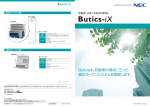
5.8 公差判定の拡大表示
公差判定の表示のみを拡大表示することができます。
」
キ−を押すと+NG,
① 公差判定モ−ドの状態で
「
OK, −NGの記号が拡大表示されます。
」
キ−を押
② 通常の公差判定モ−ドにするには、
「
します。
③ 公差判定モ−ドから通常の表示モ−ドにするには、[TOL.]
キ−を押します。
(5) Overflow
Preset value is improper. Check the set value and set it
again.
7. 仕 様 Specification
符号 *1
ID-C112
ID-C112M
ID-C112E
ID-C112T
ID-C1012H ID-C1012HM ID-C1012HE ID-C1012
ID-C1012M ID-C1012E
Model name *1
コ−ドNo.*1
543-250
543-251
543-252
543-253
543-290
543-271
Order No. *1
指示表示
12.7-0.001mm 12.7-0.001mm/.5-.00005" .../.5-.0001"
最小表示量
0.001mm
測長範囲
12.7mm = 0.5"
0.001mm/.00005"
543-291
543-292
12.7-0.01mm 12.7-0.01mm/.5-.0005"
0.001mm/.0001" 0.01mm
0.01mm/.0005"
543-270
543-272
12.7-0.01mm 12.7-0.01mm/.5-.0005"
Designations
0.01mm
Resolution
0.01mm/.0005"
Measure Range
指示精度 *2 0.003mm以下 0.003mm
(.00012")or less
0.005mm (.0002") or less
0.02mm以下 0.02mm (.0008") or less
Accuracy *2
準拠規格
ISO R463/JIS B7503
ANSI B89.1.10/AGD Gr.2 ISO R463/JIS B7503
ANSI/AGD2 ISO R463/JIS7503
ANSI/AGD2
Standards
ステム
φ8mm
φ9.52mm = 3/8"DIA
φ9.52mm φ8mm
φ9.52mm
Stem diameter
Steel(#4-48)超硬 Carbide(M2.5)
Steel(#4-48) Contact point
φ8mm
測定子
超硬 Carbide(M2.5×0.45)鋼球 Steel(#4-48UNF) 超硬 Carbide(M2.5)
測定力
1.5N以内 1.5N or less
0.9N以内 0.9N or less
Contact force
Specification of battery powered standard models
保護等級
防麈保護 IP-42
(IEC 529/JIS D0207,C0920)工場出荷時の状態において。Equivalent to IP-42(at conditions ex-works) Protection
測定方向
全方向使用可能 Useful in all directions
Plunger direction
電源
酸化銀電池 (SR44)1pc. Silver oxide cell
(SR44)1pc. #938882
Power supply
電池寿命
連続約5000時間 Approx. 5000 hours in continuous service
12 mm機種共通仕様 5.8 Magnified Indication of Tolerance Judgment
Only the indication of tolerance judgment can be magnified.
1 Pressing [
] key in the tolerance judgment mode
causes the signs of +NG, OK, and –NG indicated in
magnification.
2 To return to normal tolerance judgment mode, press
] key.
[
3 To switch to normal indication mode from the tolerance
judgment mode, press [TOL.] key.
(4) Tolerance setting error
Tolerance limit value is set with the upper limit value being
smaller than the lower limit value. Set it so that the upper
limit value is greater than the lower limit value.
(5)
電池式標準型機能仕様
7
(3) ABS data composition error
A temporary error that occurs when the spindle is moved
too fast. Keep on using the instrument since this error
does not affect measured values.
Battery life
Common Specification of 12mm models
使用温度範囲 0℃∼40℃
Operating temp.
保存温度範囲 −10℃∼60℃
Storage temp.
本体重量
約160g
(=Approx. 0.35 lbs)
Net weight
梱包重量
約300g
(=Approx. 0.66 lbs)
Gross weight
*1.ウラブタ平のものはコ−ドナンバ−に符番'B'が付き、そうでない場合は耳金付きになります。
The flat back models have a suffix of 'B' appended to the Order Numbers. Or with-lug back model have not one.
ex.ID-C112EB : 543-252B
ID-C1012B : 543-270B
*2.量子化誤差を含みません。
Not including the quantizing error.
8. オプション Optional accessories
Order No.
2
#540774
#902011
mm
TOL.
3
mm
#902794
品名
レリ−ズ レバ−Ass'y
(海外仕様品に使用)
Part Name
Release cable
Lifting lever Ass'y(for ISOtype)
Lifting lever Ass'y
(for AGDtype)
#905338
M-SPC接続ケ−ブル : 1 m
Connecting cable : 1 m
#905409
M-SPC接続ケ−ブル : 2 m
Connecting cable : 2 m
Printed in Japan
ERCQNE199071