1
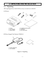
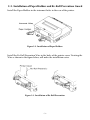
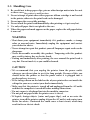
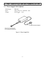
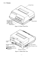
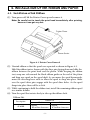
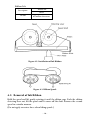
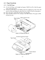
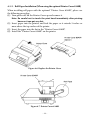
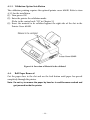
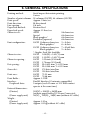
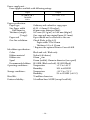
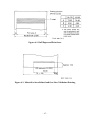
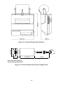
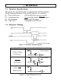
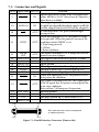
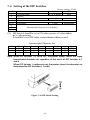
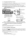
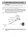
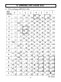
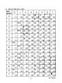
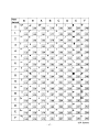
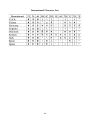
Dot Matrix Printer
DP8340RC Series
[ PARALLEL INTERFACE ]
USERS Manual
Federal Communications Commission
Radio Frequency Interference
Statement
This equipment has been tested and found to comply with the limits for a Class A digital device, pursuant to Part 15 of the FCC Rules. These limits are designed to provide reasonable protection against
harmful interference when the equipment is operated in a commercial environment. This equipment
generates, uses and can radiate radio frequency energy and, if not installed and used in accordance
with the instruction manual, may cause harmful interference to radio communications. Operation of
this equipment in a residential area is likely to cause harmful interference in which case the user will
be required to correct the interference at his own expense.
For compliance with the Federal Noise Interference Standard, this equipment requires a shielded cable.
This statement will be applied only for the printers marketed in U.S.A.
Statement of
The Canadian Department of Communications
Radio Interference Regulations
This Class A digital apparatus complies with Canadian ICES-003.
Cet appareil numérique de la classe A est conforme à la norme NMB-003 du Canada.
The above statement applies only to printers marketed in Canada.
Trademark acknowledgments
DP8340: Star Micronics Co. Ltd.
Notice
• All rights reserved. Reproduction of any part of this manual in any form whatsoever, without STAR’s
express permission is forbidden.
• The contents of this manual are subject to change without notice.
• All efforts have been made to ensure the accuracy of the contents of this manual at the time of going to
press. However, should any errors be detected, STAR would greatly appreciate being informed of them.
• The above notwithstanding, STAR can assume no responsibility for any errors in this manual.
© Copyright 1986-2008 Star Micronics Co., Ltd.
TABLE OF CONTENTS
1. Outline............................................................................................ 1
2. Unpacking and Installation.............................................. 2
2-1.Unpacking.............................................................................................. 2
2-2.Installation of Paper Holders and Re-Roll
Prevention Guard................................................................................. 3
2-3.Handling Notes..................................................................................... 4
2-4.Maintenance.......................................................................................... 5
3. Part Identification and Nomenclature...................... 6
3-1.Power Supply Unit................................................................................ 6
3-2.Printer.................................................................................................... 7
3-3.Part Functional Description................................................................ 8
4. Installation of Ink Ribbon and Paper........................... 9
4-1.Installation of Ink Ribbon................................................................... 9
4-2.Removal of Ink Ribbon...................................................................... 10
4-3.Paper Insertion.................................................................................... 11
4-3-1. For Roll Paper...............................................................................11
4-3-2. Roll Paper Installation
(When using the optional Printer Cover 8340R).....................12
4-3-3. Validation Option Installation....................................................13
4-4.Roll Paper Removal............................................................................ 13
5. Control Codes.......................................................................... 14
6. General Specifications........................................................ 15
7. Interface for Model DP8340RM
(Modular Jack Connector).......................................................... 19
7-1.Interface Specifications...................................................................... 19
7-2.Interface Timing................................................................................. 19
7-3.Connectors and Signals..................................................................... 20
7-4.Setting of the DIP Switches............................................................... 21
7-4.Setting of the DIP Switches............................................................... 22
7-6.Error Cindition Alarm Mode............................................................ 22
8. WHEN POWER IS SUPPLIED BY THE USER.............................. 23
9. CHARACTER CODE LIST.............................................................. 24
1. OUTLINE
The DP8340RC series of serial dot matrix printers is for use in ECR, POS, electronic instruments, banking machines and computer peripheral equipment.
The DP8340RC series include the following features;
1) 2 color printing (Red and Black)
2) High-speed bidirectional printing (2 line/sec, 29 or 44 columns per line)
3) 9-pin print head
4) Parallel interface (Centronics compatible)
5) Commands for expanded characters, inverted characters, emphasized
characters, red and black printing, and 10CPI or 15CPI characters etc. are
provided, which makes the printer very versatile.
6) Simultaneous Data Communication and Printing
7) 2 Peripheral Drivers
8) One line validation printing (Option)
Model Name Notation
DP8340 R C
Interface
C: Parallel Interface
Printer Type
R: R Type Printer
(3.25 inch paper)
– –
2. Unpacking and Installation
2-1. Unpacking
After opening the box, check if all necessary accessories are included.
(A) Printer
1 Printer
2 User’s Manual
3 Paper Holders
4 Re-Roll Prevention Guard
5 Ink Ribbon
6 DIP Switch Cover
(B) Power Supply Unit (Option: PS8340A)
1
1 Power Supply Unit
2 User’s Manual
Figure 2-1. Unpacking
– –
2-2.Installation of Paper Holders and Re-Roll Prevention Guard
Install the Paper Holders in the intermost holes in the rear of the printer.
Figure 2-2. Installation of Paper Holders
Install the Re-Roll Prevention Wire in the holes of the printer cover. Twisting the
Wire as shown in the figure below, will make the installation easier.
Figure 2-3. Installation of Re-Roll Prevention
– –
2-3. Handling Care
1. Be careful not to drop paper clips, pins or other foreign matter into the unit
as these cause the printer to malfunction.
2.Do not attempt to print when either paper or ribbon cartridge is not located
in the printer, otherwise the print head can be damaged.
3.Do not open the cover while printing.
4.Do not touch the print head immediately after printing as it gets very hot.
5.Use only roll paper that is not glued to the core.
6. When the paper end mark appears on the paper, replace the roll paper before
it runs out.
WARNING
PShut down your equipment immediately if it produces smoke, a strange
odor, or unusual noise. Immediately unplug the equipment and contact
your dealer for advice.
PNever attempt to repair this product yourself. Improper repair work can be
dangerous.
PNever disassemble or modify this product. Tampering with this product
may result in injury, fire, or electric shock.
PDuring and immediately after printing, the area around the print head is
very hot. Do not touch it, as you could be burned.
CAUTION
P
We recommend that you unplug the printer from the power outlet
whenever you do not plan to use it for long periods. Because of this, you
should locate the printer so that the power outlet it is plugged into is
nearby and easy to access.
P
If the voltage shown on the label on the of your printer does not match the
voltage for your area, contact your dealer immediately.
P
Make sure that the printer is turned off and unplugged from the AC outlet
and that the computer is turned off before making connections.
P
Do not connect a telephone line into the modular connector.
PDo not pull out paper while the printer cover is closed.
PIf liquids, foreign objects (coins and paper clips), and so on enter the
printer, turn off the printer, unplug it from the AC outlet, and contact your
dealer for advice. Continued use could cause a short circuit, which may
result in fire or electric shock.
– –
2-4. Maintenance
Essentially, your printer is a robust piece of equipment, but should be treated
with a modicum of care in order to avoid malfunctions. For example:
1.Keep your printer in a “comfortable” environment. Roughly speaking, if you
feel comfortable, then the environment is suitable for your printer.
2.Do not subject the printer to physical shocks or excessive vibration.
3. Avoid over-dusty environments. Dust is the enemy of all precision
mechanical devices.
4. To clean the exterior of the printer, use a cloth barely dampened with either
water with a little detergent or a little alcohol, but do not allow any liquid to
fall inside the printer.
5. The interior of the printer may be cleaned with a small cleaner or a
compressed-air aerosol (sold for this purpose). When performing this
operation, be sure not to bend or damage any cable connections or electronic
components.
– –
3. Part Identification anD Nomenclature
3-1. Power Supply Unit (Option)
Model name :
Input :
Output :
PS8340A
100 to 240V AC, 50/60 Hz 6.0A
DC12V 5% 2.0A DC Power Connector (Output)
Shape of AC Power plug will
vary according to destinations.
Figure 3-1. Power Supply Unit
– –
3-2. Printer
Figure 3-2. Printer: Front View
Do not connect this to a
telephone.
Figure 3-3. Printer: Rear View
– –
3-3. Part Functional Description
(1)
(2)
(3)
(4)
(5)
AC Power Plug :
DC Power Outlet :
Printer Cover :
POWER Lamp :
ON LINE Lamp :
Connect to an outlet of the specified voltage.
Supplies DC 12V power to the printer.
Protects the printer against dust and reduces noise.
Lights up (green LED) when power is on.
Lights up (green LED) when the unit is in the online
mode.
Lights up (red LED) when printer operation is not (6) ALARM Lamp :
normal, or the printer is out of paper. It is necessary
to install paper into the printer and press the ON
LINE Button to recover from paper empty status.
Turn off the printer power in order to recover from
abnormal operation.
(7) ON LINE Button :
Toggles between the on-line and off-line modes. The printer will go on-line after turning power on.
(8) FEED Button :
Momentary operation of this button provides one
line feed. Pressing this button continuously will
cause continuous paper feed. If power is turned on
while pressing this button, self printing*1 will be
performed.
(9) Interface Connector : Connects the printer to host computers. Check that
both computer and printer are off before connecting.
(10)DIP Switches :
Allows for setting of various functions according to
user requirements.
(11)Peripheral Drive
Connects the printer to the peripheral devices such
Output :
as Cash Drawer, Paper Cutter and Paper Take-Up
Device etc. to drive them.
*1 Self Printing
This printer has another convenient function, the
Automatic Test Printing. With the ink ribbon and
paper properly installed in the printer, turn the power ON while holding down the Feed switch. Test
printing will start and stop again automatically.
– –
4. Installation of Ink Ribbon and Paper
4-1. Installation of Ink Ribbon
(1) Turn power off, lift the Printer Cover up and remove it.
Note: Be careful not to touch the print head immediately after printing, because it can get very hot.
Figure 4-1. Printer Cover Removal
(2) Unwind ribbon so that the spools are separated as shown in Figure 4-3.
Hold the ribbon taut as shown with the drive pins facing down and slide the ribbon between the print head and the platen. While keeping the ribbon
taut, wrap one side around the black ribbon guide on the end of the platen
and drop one spool on the spool shaft. As you move the spool downwards,
move the detecting lever aside to allow the spool to drop into place. Make
sure the spool drive pins engage with the spool drive holes. As the spool
drops into place there will be a click.
(3) While continuing to hold the ribbon taut, install the remaining ribbon spool
in a similar fashion.
(4) Turn the spool that rotates freely to take up the ribbon slack.
Ribbon Life
Ribbon life
Description
Black
Red
A
pprox.
Approx.
SF-03BR
0.8
million
characters
0.4
million characters
– –
Ribbon Life
Description Ribbon life
Black
Approx.
SF-03B
0.8 million characters
Figure 4-2. Installation of Ink Ribbon
Figure 4-3. Ribbon Spools
4-2. Removal of Ink Ribbon
Hold the spool and lift gently, rotating it until the ribbon sags. Push the ribbon
detecting lever out, lift the spool until it comes off the shaft. Remove the second
spool in a similar manner.
(Do not apply excessive force when lifting spools.)
– 10 –
4-3. Paper Insertion
4-3-1. For Roll Paper
(1) Cut the Roll Paper end straight and square. Hold the roll so that the paper
comes from the bottom.
(2) Attach the Roll Paper to the Holders Paper by slipping one side of the roll
onto the Hub and pulling the other Hub out to allow the roll to slip in place.
(3) Insert the paper evenly into the Paper Insertion Slot.
(4) Turn the Power Switch “ON”, and press the FEED Button. The paper will be
fed into the unit.
Figure 4-4. Paper Insertion (1)
Figure 4-5. Paper Insertion (2)
– 11 –
4-3-2. Roll Paper Installation (When using the optional Printer Cover 8340R)
When installing roll paper with the optional “Ptinter Cover 8340R”, please use
the following procedure.
(1) Turn power off, lift the Printer Cover up and remove it.
Note: Be careful not to touch the print head immediately after printing
because it can get very hot.
(2) Insert paper into the printer, and feed the paper so it extends 3 inches or
more above the top surface of the printer.
(3) Insert the paper into the slot in the “Printer Cover 8340R”.
(4) Install the “Printer Cover 8340R” on the printer.
Figure 4-6. Replace the Printer Cover
Figure 4-7. Printer Cover 8340R
– 12 –
4-3-3. Validation Option Installation
The validation printing requires the optional printer cover 8340R. Refer to item
4-3-2 for the installation.
(1) Turn power ON.
(2) Enter the printer the validation mode.
(Refer to the control code “GS” in Chapter 5.)
(3) Insert the material to be validated against the right side of the slot in the
Printer Cover 8340R.
Figure 4-8. Insertion of Material to be validated
4-4.
Roll Paper Removal
Cut the paper close to the slot and use the feed button until paper has passed
completely through the printer.
Note: Do not try to remove the paper by hand as it could become crooked and
get jammed inside the printer.
– 13 –
5. Control Codes
Character Code List
Character
1
2
3
4
5
6
7
8
9
10
11
12
13
14
15
16
17
18
19
20
21
22
23
24
25
26
LF
CR
SO
DC4
ESC-1
ESC-0
SI
DC2
ESC E ESC F
ESC 4
ESC 5
ESC a n
ESC C n ESC N n
ESC O
FF
ESC @
ESC BEL n1 n2
BEL
FS
SUB
CAN
ESC P
ESC M
GS
Code
(0A)H
(0D)H
(0E)H
(14)H
(1B)H (2D)H(01)H (1B)H (2D)H (31)H
(1B)H (2D)H(00)H
(1B)H (2D)H (30)H
(0F)H
(12)H
(1B)H (45)H
(1B)H (46)H
(1B)H (34)H
(1B)H (35)H
(1B)H (61)H n
(1B)H (43)H n
(1B)H (4E)H n
(1B)H (4F)H
(0C)H
(1B)H (40)H
(1B)H (07)H
n1 n2
(07)H
(1C)H
(1A)H
(18)H
(1B)H (50)H
(1B)H (4D)H
(1D)H
Function
Print and line feed instruction
Print and line feed instruction
(same as LF)
Expanded character instruction
Expanded character release
Underline instruction
Underline release
Inverted print instruction
Inverted print release
Emphasized print instruction
(one-way printing)
Emphasized print release
Red character print instruction
Red character print release
n-line feed instruction
Sets page length in lines
1 n 120 (default n = 42)
Set bottom margin in lines
0 n 120 (default n = 0)
Cancel Bottom margin
Form feed
Printer initialization instruction
Set peripheral unit drive 1 pulse duration
1 n1 127, 1 n2 127
(default n1 = n2 = 20)
Trigger peripheral unit drive 1 (Deferred)
Trigger peripheral unit drive 1
(Immediate)
Trigger peripheral unit drive 2
(Immediate)
Clears print buffer
Select 10 CPI
Select 15 CPI (Default value)
Validation printing instruction
– 14 –
6. General Specifications
Printing method :
Serial impact dot matrix printing,
9 wires
Number of print columns : 29 columns (10CPI), 44 columns (15CPI)
Print speed :
Approx. 2 lines/sec
Print direction :
Bi-directional
Line spacing :
1/6 inch
Paper feed method :
Friction Feed
Paper feed speed :
Approx. 12 lines/sec
Character set :
ASCII
96 characters
Special
64 characters
Block graphics*
64 characters
Katakana (Japanese)
64 characters
Font configuration :
10CPI Ordinary characters 5 × 9 dots
Block graphics*
6 × 6 dots
15CPI Ordinary characters 7 × 9 half dots
Block graphics*
5 × 6 dots
* Graphic Feed Not Available
Character size :
10CPI 2.00 (H) × 2.42 (V) mm
15CPI 1.32 (H) × 2.42 (V) mm
Character spacing :
10CPI 2.55 mm (1/10 inch)
15CPI 1.70 mm (1/15 inch)
Dot spacing :
10CPI H=0.425 mm V=0.353 mm
15CPI H=0.340 mm V=0.353 mm
Gross dot :
10CPI 174 dots/wire/line
15CPI 220 dots/wire/line
Print area :
10CPI 73.53 mm
15CPI 74.46 mm
Print Buffer :
Approx. 1.5 KB
Interface :
Parallel Interface (Centronics compatible)
Peripheral drive
2 outputs (each 1A max. at 12V. Both cannot
operate at the same time.)
External dimensions :
(Printer)
202(W) × 200(D) × 98(H) mm
(without paper holder, DC Power Connector)
(Power supply unit)
54(W) × 114(D) × 36(H) mm (without AC cable)
Weight :
(Printer)
Approx. 1.9 kg
(Power supply unit)
Approx. 0.3 kg (without AC cable)
– 15 –
Power supply unit :
Four supplies available with following ratings
Input
Output
AC 100 to 240 V 50/60 Hz
0.6 A
DC 12.0 V ± 5%
2.0 A
Paper specification :
Paper type
Ordinary and carbonless copy paper
Size Paper width
82.55 ± 0.5mm (3.25 inches)
Roll diameter
80 mm outer diameter (Max)
Thickness (single)
0.07 mm (52.3 g/m2) to 0.09 mm (64g/m2)
(2 copy)
One copy and one original (max 0.13 mm)
Paper end
Paper should not be attached to the core
One line validation
Check (Refer to Fig. 6-2)
Paper width 70 to 90 mm
Thickness 0.1 to 0.15 mm
* Requires the optional Printer Cover 8340R
Ink ribbon specification :
Black and red / Black only
Color
Ribbon material
Nylon (#40 denier)
Ribbon size
13mm × 6m
Spool
13mm (width), 35mm in diameter (two spool)
Recommended ribbon SF-03BR (Black and red), SF-03B (Black)
Operating conditions :
Temperature
+5˚C to +40˚C
Humidity
10% to 80%RH
Storage conditions :
Temperature –20˚C to +70˚C
Humidity
5% to 95%RH (+40˚C)
Head life :
70 million characters
Printer reliability :
5.0 million lines MCBF (except head life)
– 16 –
Figure 6-1. Roll Paper and Print Area
Figure 6-2. Material to be validated and One Line Validation Printing
– 17 –
54 mm
Figure 6-3. External Dimensions (Printer)
36 mm
114 mm
2.0 m
Shape of AC Power plug will
vary according to destinations.
Figure 6-4. External Dimensions (Power Supply Unit)
– 18 –
7. INterface
7-1. Interface Specifications
This printer has a parallel interface to communicate with the computer.
The operating specifications of the parallel interface are as follows.
(1) Data transfer rate
1000 to 6000 characters per second
(2) Synchronization
Via externally supplied STROBE pulses
(3) Handshaking
ACK and BUSY signals
(4) Logic level
Compatible with TTL level
7-2. Interface Timing
Figure 7-1. Interface Timing Diagram
Signal Name
DATA1-DATA8
(To Printer)
Circuit Example
74LS Compatible
74LS Compatible
STROBE
(To Printer)
BUSY, ACK
(From Printer)
74LS Compatible
Figure 7-2. Typical Interface Circuit
– 19 –
7-3. Connectors and Signals
Pin No. Signal Name IN/OUT
Function
Signals when data is ready to be read.Signal goes
1
STROBE
IN
from HIGH to LOW (for at least 0.5 microsec.)
when data is available.
These signals provide the information of the first
2-9
DATA1-8
IN to eighth bits of parallel data.Each signal is at HIGH
level for a logical 1 and at a LOW level for a logical 0.
A 9
microsecond LOW pulse acknowledges
10
OUT
ACK
receipt of data.
When this signal goes LOW, the printer is ready
to accept data. When the printer is in one of the
11
BUSY
OUT conditions below.”HIGH” is set.
1. Data being entered.
2. Off line.
3. Error condition.
12
PAPER
OUT This signal is normally LOW. It will go HIGH if the
OUT
printer runs out of paper.
13 SELECTED OUT This signal is HIGH when the printer is online.
-
Unused
14-15
16 SIGNAL GND
Signal ground.
17 CHASSIS GND
Chassis ground, isolated from logic ground.
18
LOGIC
This pin is pulled-up 4.7 kW resistor to +5V.
19-30
GND
Twisted pair return signal ground level.
When this signal gose LOW, the printer is reset
31
RESET
IN
to its power-on condition.
This signal is normally HIGH. This signal goes
32
ERROR
OUT LOW to signal that the printer cannot print due
to an error condition.
Refer to Item 7-6 Emergency Suspension.
33 EXT GND
External ground.
34
-
Unused
35
+5V
This pin is pulled-up 2.2 kW resistor to +5V.
36 SELECT IN
Unused
(18)
(1)
This connector mates with an Amphenol
57-30360 connector.
(36)
(19)
Figure 7-3. Parallel Interface Connector (Printer side)
– 20 –
7-4. Setting of the DIP Switches
Switch
1
2
3
4
5 (*1)
6
7
8
Factory settings : all ON
ON
OFF
U.S.A. & Europe
Japan
Function
Character Table Unused
CR cord
Unused
Ink Ribbon
Disable
Enable
2-color
Monochrome
International Character Set (See below)
(*1) DIP Swich 5 should be set to ON when you use a 2-color ribbon
for 2-color printing.
It should be set to OFF when a monochrome ribbon is used.
SW NO. USA
6
ON
7
ON
8
ON
International Character Set
France Germany England Denmark Sweden
OFF
ON
OFF
ON
OFF
ON
OFF
OFF
ON
ON
ON
ON
ON
OFF
OFF
Itary
ON
OFF
OFF
Spain
OFF
OFF
OFF
Note: When DIP Switches 1 is set to OFF, the printer always selects the Japan
international character set regardless of the status of DIP Switches 6, 7
and 8.
When DIP Swiches 1 is otherwise set, the printer selects the character set
determined by DIP Switches 6, 7 and 8.
Figure 7-4. DIP Switch Setting
– 21 –
7-5. Peripheral Unit Drive Circuit
The Control Board of this printer is equipped with a circuit for driving peripheral units (Paper Cutter, Take-Up Device, Cash Drawer, etc.)
The 6P Modular Jack is used as the Drive Circuit. When using this circuit, connect the peripheral unit cable to the 6P Modular Jack (cable is not included).
Note: Peripheral unit drive circuit connector only connects to peripheral units
such as cash drawers, etc.
Do not connect it to a telephone.
CN8
1. Drive Circuit
F.G.
1 Frame Ground(F.G.)
Drive 12V,MAX. 1A
2 Peripheral Drive 1
Output
+12V
D1
D1
D2
Absolute Ratings (Ta = 25˚C)
Voltage Breakdown
400V
Peak Forward Current
1A
3 +12V
2A
D2
4 +12V
5 Peripheral Drive 2
Note: It is impossible to drive pe6 Motor Ground(M.G.)
ripheral devices 1 and 2 at
the same
time. To drive
[Printer side]
Figure 7-5. Drive Circuit
them continuously, set the
duty cycle ratio to 20% or
Modular plug: MOLEX 90075-0007,
less. AMP641337, or BURNDY B-66-4
Figure 7-6. 6P Modular Jack Connector
Figure 7-7. Recommend Cable
Note: Make sure that the metal structural parts of the peripheral device are connected to frame Ground (Pin 1) to provide a static drain path.
2. Control code
Codes for Drive Circuit control are ESC BEL n1 n2, BEL, FS and SUB.
Refer to the Control Codes in Section 5.
7-6. Error Condition Alarm Mode
If an error condition is detected during operation, the printer will stop printing and cause the ERROR signal to go Low. All solenoids & motors will be deenergized. It is necessary to turn the printer power off and on again in order to
recover from the alarm mode.
The printer can detect the following error conditions:
a. Motor Lock
b. Defective timing detector
c. Micro-processor out of program sequence
– 22 –
8. When power is supplied by the user
Note : The optional AC adapter (PS8340A) has been designed specifically for
this unit(DP8340).
Other AC adapters may not meet the EMC technical standards.
When printer power is supplied by the user rather than through the accessory
power source unit, please be careful of the following points.
Note 1: An electrolytic capacitor (C = 4700µF/25V to 6800µF/25V) must be
connected across the output of the power supply. Use a power supply
of DC 12 V ± 5% and more than 2.0 A with SELV output and LPS or Class
2 (double-insulation structure) output approved by IEC60950.
Note 2: A DC power plug is available as an option.
GND
+12V
GND
Note 3: Be careful about installing the printer in an area where there is noise.
Take the appropriate measures to protect against electrostatic AC line
noise, etc.
– 23 –
9. Character Code List
1) U.S.A. & Europe (DIP SW1: ON)
– 24 –
– 25 –
2) JAPAN (DIP SW1: OFF)
– 26 –
– 27 –
International Character Sets
– 28 –
OVERSEAS SUBSIDIARY COMPANIES
STAR MICRONICS AMERICA, INC.
SPECIAL PRODUCTS DIVISION
STAR MICRONICS CO., LTD.
536 Nanatsushinya, Shimizu-ku, Shizuoka,
424-0066 Japan
Tel: (int+81)-54-347-0112
Fax: (int+81)-54-347-0409
Please access the following URL
http://www.star-m.jp/eng/dl/dl02.htm
for the latest revision of the manual.
1150 King Georges Post Road, Edison, NJ 08837-3729 U.S.A.
Tel: (int+1)-732-623-5500, Fax: (int+1)-732-623-5590
STAR MICRONICS EUROPE LTD.
Star House, Peregrine Business Park, Gomm Road,
High Wycombe, Bucks, HP13 7DL, U.K.
Tel: (int+44)-1494-471111, Fax: (int+44)-1494-473333
STAR MICRONICS ASIA LTD.
Rm. 1901-5, 19/F., Enterprise Square Two,
3 Sheung Yuet Road, Kowloon Bay, Hong Kong
Tel : (int+852)-2796-2727, Fax : (int+852)-2799-9344
2008.07.18
Printed in Japan, 80870196


![User`s Manual DP8340II R SERIES [Serial]](http://vs1.manualzilla.com/store/data/005993516_1-f706d7540b19c5fecea062c6335f03cc-150x150.png)
![User's Manual DP8340II SERIES [Parallel]](http://vs1.manualzilla.com/store/data/006876520_1-e14f27ca3e82bd4fbe61e6010073af1e-150x150.png)

![User's Manual DP8340II SERIES [Serial]](http://vs1.manualzilla.com/store/data/006863352_1-7c329c58d43827994f443f796586090a-150x150.png)