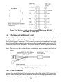
1
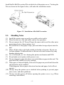
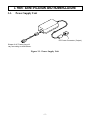
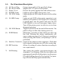
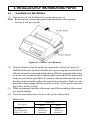
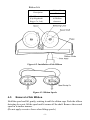
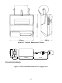
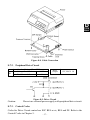
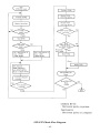
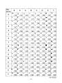
DOT MATRIX PRINTER
DP8340R SERIES
[SERIAL INTERFACE]
USERS MANUAL
Federal Communications Commission
Radio Frequency Interference
Statement
This equipment has been tested and found to comply with the limits for a Class A digital device,
pursuant to Part 15 of the FCC Rules. These limits are designed to provide reasonable protection
against harmful interference when the equipment is operated in a commercial environment.
This equipment generates, uses and can radiate radio frequency energy and, if not installed and
used in accordance with the instruction manual, may cause harmful interference to radio
communications. Operation of this equipment in a residential area is likely to cause harmful
interference in which case the user will be required to corect the interference at his own expense.
For compliance with the Federal Noise Interference Standard, this equipment requires a
shielded cable.
This statement will be applied only for the printers marketed in U.S.A.
Statement of
The Canadian Department of Communications
Radio Interference Regulations
This digital apparatus does not exceed the Class A limits for radio noise emissions from digital
apparatus set out in the Radio Interference Regulations of the Canadian Department of
Communications.
Le présent appareil numérique n’émet pas de bruits radioélectiques dépassant les limites
applicables aux appareils numériques de la classe A prescrites dans le Règlement sur le
brouillage radioélectrique édicté par le ministère des Communications du Canada.
The above statement applies only to printers marketed in Canada.
Trademark acknowledgments
DP8340R: Star Micronics Co. Ltd.
Notice
•
•
•
•
All rights reserved. Reproduction of any part of this manual in any form whatsoever, without STAR’s express
permission, is strictly forbidden.
The contents of this manual are subject to change without notice.
All efforts have been made to ensure the accuracy of the contents of this manual at the time of printing. However,
should any errors be found, STAR would greatly appreciate being informed of them.
The above notwithstanding, STAR can assume no responsibility for any errors in this manual.
© Copyright 1988, 1999 Star Micronics Co., Ltd.
TABLE OF CONTENTS
1. OUTLINE .............................................................................................. 1
2. UNPACKING AND INSTALLATION ................................................ 2
2-1. Unpacking .................................................................................... 2
2-2. Installation of Paper Holders and Re-Roll
Prevention Guard ......................................................................... 3
2-3. Handling Notes............................................................................. 4
3. PART IDENTIFICATION AND NOMENCLATURE ........................ 5
3-1. Power Supply Unit ....................................................................... 5
3-2. Printer ........................................................................................... 6
3-3. Part Functional Description.......................................................... 7
4. INSTALLATION OF INK RIBBON AND PAPER ............................. 8
4-1. Installation of Ink Ribbon ............................................................ 8
4-2. Removal of Ink Ribbon ................................................................ 9
4-3. Paper Insertion ........................................................................... 10
4-3-1. For Roll Paper ................................................................. 10
4-3-2. Roll Paper Installation
(When using the optional Printer Cover 8340R) ............. 11
4-3-3. Validation Option Installation ......................................... 12
4-4. Roll Paper Removal ................................................................... 12
5. CONTROL CODES ............................................................................ 13
6. GENERAL SPECIFICATIONS .......................................................... 20
7. INTERFACE FOR MODEL DP8340RM
(MODULAR JACK CONNECTOR) .................................................. 24
7-1. Interface Specifications .............................................................. 24
7-2. Interface Circuit ......................................................................... 24
7-3. Setting of the DIP Switches ....................................................... 25
7-3-1. DIP-SW 1 ........................................................................ 25
7-3-2. DIP-SW2 ......................................................................... 25
7-4. Connectors and Signals .............................................................. 26
7-5. Interface Connections................................................................. 27
7-6. Peripheral Unit Drive Circuit ..................................................... 28
7-6-1. Cable Connection ............................................................ 28
7-6-2. Peripheral Drive Circuit .................................................. 29
7-6-3. Control Codes .................................................................. 29
8. INTERFACE FOR MODEL DP8340RD
(D-SUB 25 PIN CONNECTOR) ......................................................... 30
8-1. Interface Specifications .............................................................. 30
8-2. Interface Circuit ......................................................................... 31
8-2-1. RS-232C .......................................................................... 31
8-2-2. Current Loop ................................................................... 31
8-3. Setting of the DIP Switches ....................................................... 32
8-3-1. DIP-SW 1 ........................................................................ 32
8-3-2. DIP-SW 2 ........................................................................ 32
8-4. Jumper Setting ............................................................................ 33
8-4-1. Removal of the Bottom Cover ........................................ 33
8-4-2. Setting of Jumper ............................................................ 33
8-5. Connectors and Signals .............................................................. 34
8-6. Interface Connections................................................................. 35
8-7. Peripheral Unit Drive Circuit ..................................................... 36
8-7-1. Cable Connection ............................................................ 36
8-7-2. Peripheral Drive Circuit .................................................. 37
8-7-3. Control Codes .................................................................. 37
9. DATA STRUCTURE AND CONTROL ............................................ 38
9-1. DTR Mode (1 BLOCK) ............................................................. 38
9-2. X-ON/X-OFF Mode ................................................................... 39
9-3. STX-ETX Mode ......................................................................... 41
10. CHARACTER CODE LIST .............................................................. 43
11. WHEN POWER IS SUPPLIED BY THE USER ............................. 46
1. OUTLINE
The DP8340R series of serial dot matrix printers is for use in ECR, POS,
electronic instruments, banking machines and computer peripheral equipment.
The DP8340R series include the following features;
1) 2 color printing (Red and Black)
2) High-speed bidirectional printing (2 line/sec, 29 or 44 columns per line)
3) 9-pin print head
4) The interface conforms to RS-232C in M type, and to RS-232C/20mA
Current Loop in D type.
5) Commands for expanded characters, inverted characters, emphasized
characters, red and black printing, and 10CPI or 15CPI characters etc. are
provided, which makes the printer very versatile.
6) Simultaneous Data Communication and Printing
7) Error Checking Protocol
8) Peripheral Driver
9) One line validation printing (Option)
Model Name Notation
–1–
2. UNPACKING AND INSTALLATION
2-1.
Unpacking
After opening the box, check if all necessary accessories are included.
(A) Printer
1 Printer
2 User’s Manual
3 Paper Holders
4 Re-Roll Prevention Guard
5 Ink Ribbon
6 DIP Switch Cover
(B) Power Supply Unit
1
1 Power Supply Unit
2 User’s Manual
Figure 2-1. Unpacking
–2–
2-2.
Installation of Paper Holders and Re-Roll Prevention Guard
Install the Paper Holders in the intermost holes in the rear of the printer.
Figure 2-2. Installation of Paper Holders
–3–
Install the Re-Roll Prevention Wire in the holes of the printer cover. Twisting the
Wire as shown in the figure below, will make the installation easier.
Figure 2-3. Installation of Re-Roll Prevention
2-3.
Handling Notes
(1)
(2)
(3)
Install the printer near an easily accessible socket-outlet.
Place the unit on a flat and stable surface for operation.
Do not connect the AC Power Plug to the same outlet used for other noise
generating devices (large motors, etc.).
(4) Be careful not to drop paper clips, pins and other foreign objects into the
unit.
(5) Wipe off dirt with a soft cloth soaked in alcohol or benzine. Do not use
Lacquer thinner, Trichlorethelene or Ketone solvents because they may
damage plastic parts.
(6) Use a soft brush, etc. for cleaning the printer mechanism and PCB.
(7) Keep hands out of printer while power is on.
(8) Do not attempt to print when there is no ink ribbon or paper in the unit. The
print head life could be severly reduced.
(9) If the paper is fastened tightly to the roll, the paper may not detach from the
roll when the end is reached.
If this happens, the no paper detection function and paper feed will not
operate.
(10) Always keep the printer cover attached when printing to prevent paper
jams, noise, and other problems.
(11) Always turn the power off before opening the printer cover. (e.g. When
renewing a ink ribbon)
–4–
3. PART IDENTIFICATION AND NOMENCLATURE
3-1.
Power Supply Unit
DC Power Connector (Output)
Shape of AC Power plug will
vary according to destinations.
Figure 3-1. Power Supply Unit
–5–
3-2.
Printer
Figure 3-2. Printer: Front View
Figure 3-3. Printer: Rear View
–6–
3-3.
Part Functional Description
(1)
(2)
(3)
(4)
(5)
AC Power Plug
DC Power Outlet
Printer Cover
POWER Lamp
ON LINE Lamp
Connect to an outlet of the specified voltage.
Supplies DC 12V power to the printer.
Protects the printer against dust and reduces noise.
Lights up (green LED) when power is on.
Lights up (green LED) when the unit is in the online
mode.
(6) ALARM Lamp
Lights up (red LED) when printer operation is not
normal, or the printer is out of paper. It is necessary
to install paper into the printer and press the ON
LINE Button to recover from paper empty status.
Turn off the printer power in order to recover from
abnormal operation.
(7) ON LINE Button
Toggles between the on-line and off-line modes. The
printer will go on-line after turning power on.
(8) FEED Button
Momentary operation of this button provides one
line feed. Pressing this button continuously will
cause continuous paper feed. If power is turned on
while pressing this button, self printing*1 will be
performed.
(9) Interface Connector Connects the printer to host computers. Check that
both computer and printer are off before connecting.
(10) DIP Switches
Allows for setting of various functions according to
user requirements.
*1
Self Printing
This printer has another convenient function, the
Automatic Test Printing. With the ink ribbon and
paper properly installed in the printer, turn the power
ON while holding down the Feed switch. Test printing will start and stop again automatically.
–7–
4. INSTALLATION OF INK RIBBON AND PAPER
4-1.
Installation of Ink Ribbon
(1) Turn power off, lift the Printer Cover up and remove it.
Note: Be careful not to touch the print head immediately after printing,
because it can get very hot.
Figure 4-1. Printer Cover Removal
(2)
(3)
(4)
Unwind ribbon so that the spools are separated as shown in Figure 4-3.
Hold the ribbon taut as shown with the drive pins facing down and slide the
ribbon between the print head and the platen. While keeping the ribbon taut,
wrap one side around the black ribbon guide on the end of the platen and
drop one spool on the spool shaft. As you move the spool downwards, move
the detecting lever aside to allow the spool to drop into place. Make sure the
spool drive pins engage with the spool drive holes. As the spool drops into
place there will be a click.
While continuing to hold the ribbon taut, install the remaining ribbon spool
in a similar fashion.
Turn the spool that rotates freely to take up the ribbon slack.
Ribbon Life
Description
SF-03BR
(Fuji Kagakushi
Kogyo Co., Ltd.)
Ribbon life
Black
Red
Approx.
0.8 million
characters
–8–
Approx.
0.4 million
characters
Ribbon Life
Ribbon life
Description
Black
SF-03B
(Fuji Kagakushi
Kogyo Co., Ltd.)
Approx.
0.8 million
characters
Figure 4-2. Installation of Ink Ribbon
Figure 4-3. Ribbon Spools
4-2.
Removal of Ink Ribbon
Hold the spool and lift gently, rotating it until the ribbon sags. Push the ribbon
detecting lever out, lift the spool until it comes off the shaft. Remove the second
spool in a similar manner.
(Do not apply excessive force when lifting spools.)
–9–
4-3.
Paper Insertion
4-3-1. For Roll Paper
(1)
(2)
(3)
(4)
Cut the Roll Paper end straight and square. Hold the roll so that the paper
comes from the bottom.
Attach the Roll Paper to the Holders Paper by slipping one side of the roll
onto the Hub and pulling the other Hub out to allow the roll to slip in place.
Insert the paper evenly into the Paper Insertion Slot.
Turn the Power Switch “ON”, and press the FEED Button. The paper will
be fed into the unit.
Figure 4-4. Paper Insertion (1)
Figure 4-5. Paper Insertion (2)
– 10 –
4-3-2. Roll Paper Installation (When using the optional Printer Cover 8340R)
When installing roll paper with the optional “Ptinter Cover 8340R”, please use
the following procedure.
(1) Turn power off, lift the Printer Cover up and remove it.
Note: Be careful not to touch the print head immediately after printing
because it can get very hot.
(2) Insert paper into the printer, and feed the paper so it extends 3 inches or
more above the top surface of the printer.
(3) Insert the paper into the slot in the “Printer Cover 8340R”.
(4) Install the “Printer Cover 8340R” on the printer.
Figure 4-6. Replace the Printer Cover
Figure 4-7. Printer Cover 8340R
– 11 –
4-3-3. Validation Option Installation
The validation printing requires the optional printer cover 8340R. Refer to
item 4-3-2 for the installation.
(1) Turn power ON.
(2) Enter the printer the validation mode.
(Refer to the control code “GS” in Chapter 5.)
(3) Insert the material to be validated against the right side of the slot in the
Printer Cover 8340R.
Figure 4-8. Insertion of Material to be validated
4-4.
Roll Paper Removal
Cut the paper close to the slot and use the feed button until paper has passed
completely through the printer.
Note: Do not try to remove the paper by hand as it could become crooked and
get jammed inside the printer.
– 12 –
5. CONTROL CODES
CODE
FUNCTION
LF
(0A)H
Print and line feed instruction
OUTLINE
The LF code causes the data in the line buffer to be printed,
followed by a single line feed. When the line buffer is empty,
only the feed takes place.
CODE
CR
(0D)H
Print and line feed instruction
FUNCTION
OUTLINE
Same function as of LF code.
However, when the DIP switch 2-4 is ON, the CR code
becomes invalid.
CODE
SO
(0E)H
Expanded character instruction
FUNCTION
OUTLINE
This code causes the printer to print expanded characters
twice as wide as the regular ones. This remains in effect until
a DC4 code is received.
CODE
DC4
(14)H
Release from expanded characters
FUNCTION
OUTLINE
The expanded character instruction is released by the DC4
code, and the succeeding data is printed as regular width
characters.
CODE
ESC-1
(1B)H (2D)H (01)H or (1B)H (2D)H (31)H
Underline mode selection
FUNCTION
OUTLINE
All data received after this code is underlined until a ESC-0
is received.
CODE
FUNCTION
ESC-0
(1B)H (2D)H (00)H or (1B)H (2D)H (30)H
Release from underline mode
OUTLINE
The underline mode selection is released by this code.
– 13 –
CODE
FUNCTION
SI
(0F)H
Inverted print instruction
OUTLINE
This function causes the printing to be inverted. This code
must be received at the beginning of a line. If this code is
received anywhere other than at the beginning of a line, it is
disregarded. Accordingly, normal characters and inverted
characters, can not be mixed on the same line.
CODE
DC2
(12)H
Release from inverted print instruction
FUNCTION
OUTLINE
The inverted print instruction is released by this code. This
code must be received at the beginning of a line.
CODE
ESC E
(1B)H (45)H
Emphasized print mode instruction
FUNCTION
OUTLINE
Data following this command is printed with emphasized
characters.
In this mode, characters are printed in a single direction.
CODE
FUNCTION
ESC F
(1B)H (46)H
Release from emphasized print instruction
OUTLINE
Emphasized print is released.
CODE
ESC 4
(1B)H (34)H
Red character print instruction
FUNCTION
OUTLINE
This command causes subsequent data to be printed with red
characters.
The instruction is released by the code, ESC 5.
Red and black characters may be intermixed.
This command is ignored when DIP SW 2-3 is OFF.
CODE
FUNCTION
ESC 5
(1B)H (35)H
Release from red character print instruction
OUTLINE
The red character print instruction is released by this code.
– 14 –
CODE
FUNCTION
ESC a n
(1B)H (61)H n
n-line feed
OUTLINE
After printing the data in the current line, n lines are fed by this
code. The value of n ranges from 1 to 120.
CODE
ESC C n
(1B)H (43)H n
Sets page length in lines
FUNCTION
OUTLINE
This code sets the length of a page to n lines. The value of n
ranges from 1 to 120. On initialization, the page length
default condition will be 42 lines. The line feed pitch is onesixth inch.
CODE
ESC Nn
(1B)H (4E)H n
Sets bottom margin in lines
FUNCTION
OUTLINE
Upon receiving this code, the bottom margin is set to n lines.
0
n 120; Default Value n = 0
CODE
FUNCTION
ESC O
(1B)H (4F)H
Cancels bottom margin.
OUTLINE
Upon input of this code, bottom margin setting is cleared.
CODE
FF
(0C)H
Form feed
FUNCTION
OUTLINE
The FF code prints the data in the current line and transports
the paper to the start of the next page.
– 15 –
CODE
FUNCTION
ESC @
(1B)H (40)H
Printer initialization
OUTLINE
All printing conditions except ESC BEL n1 n2, the line buffer
and data buffer are set to the power on default condition.
CODE
ESC BEL n1 n2
(1B)H (07)H n1 n2
Sets peripheral unit drive pulse duration.
FUNCTION
OUTLINE
This command sets the pulse duration for peripheral unit
drive (Paper Cutter, Take-Up Device, cash drawer, etc.)
Pulse Duration = 10 × n1 (ms)
Delay = 10 × n2 (ms)
1
n1
127; 1 n2
127
Default value: n1 = n2 = 20
Executed by BEL code and FS code after printing.
CODE
FUNCTION
OUTLINE
BEL
(07)H
Trigger peripheral unit drive (Deferred)
Causes a peripheral drive pulse to be generated. This code is
normally stored in the buffer and is performed as it is received
from the data queue.
– 16 –
FUNCTION
FS
(1C)H
Trigger peripheral unit drive (immediate)
OUTLINE
Causes a peripheral drive pulse to be generated immediately
CODE
ENQ
(05)H
Enquiry
CODE
FUNCTION
OUTLINE
When this code is received, the printer outputs status data.
If it is input after text data input in the STX-ETX mode, the
printer outputs status data and the check byte.
CODE
STX
(02)H
Start of text
FUNCTION
OUTLINE
When this code is received, the printer enters the STX-ETX
mode. This code is ignored if received when STX-ETX mode
is already in effect.
CODE
ETX
(03)H
End of text
FUNCTION
OUTLINE
When this code is received, the printer leaves the STX-ETX
mode. Contents of the data buffer is printed, this code is
ignored if received before ENQ.
CODE
CAN
(18)H
Clears print buffer
FUNCTION
OUTLINE
Upon input of this code the data buffer and line buffer is
cleared.
CODE
ESC P
(1B)H (50)H
Select 10 CPI
FUNCTION
OUTLINE
This code causes the printer to print at 10 CPI. The number
of columns per is 29.
– 17 –
CODE
FUNCTION
ESC M
(1B)H (4D)H
Select 15 CPI
OUTLINE
This code causes the printer to print at 15 CPI. The number
of columns per line is 44. When the power is turned on, the
15 CPI mode is selected.
CODE
GS
(1D)H
Validation printing instruction
FUNCTION
OUTLINE
REMARKS
This code causes the printer to perform validation printing
of a maximum of 32 subsequent characters (at 15 CPI, from
the thirteenth to the forty-forth column).
After the GS code is received, a maximum of 32 characters
should be input, followed by the LF code which indicates
the end of the validation printing data.
(At this time, control codes except FS, ENQ, CAN and SUB
codes, or any character received beyond the limit of 32
characters are ignored.)
When the printer enters the validation mode, the ribbon is
shifted up and the ON-LINE lamp blinks. (This lamp goes
on and off at a 0.5-second interval until the end of the validation mode.) After the material to be validated is inserted,
and the LF button is pressed, the validate line is printed,
followed by a single line feed. When the check is removed
and the ON-LINE button is pressed, the printer returns to
regular mode and is set to ON-LINE status.
1) The print settings by commands (such as emphasized
mode and underline mode) are invalid only during validation printing.
2) When the CAN code is received in the validation mode,
the printer returns to regular mode, and the mechanism
is initialized.
3) If the FS or SUB codes is received in the validation
mode, these codes are executed just after the printer
returns to regular mode.
4) In the validation mode, the LF button and the ON-LINE
button do not work except the above behavior.
5) If the printer has a Red black ribbon installed, the validate line will be printed in red.
– 18 –
Character Code List
Character
Code
1 LF
2 CR
(0A)H
(0D)H
3 SO
4 DC4
5 ESC-1
7 SI
8 DC2
9 ESC E
(0E)H
(14)H
(1B)H (2D)H(01)H
(1B)H (2D)H (31)H
(1B)H (2D)H(00)H
(1B)H (2D)H (30)H
(0F)H
(12)H
(1B)H (45)H
10
11
12
13
14
ESC F
ESC 4
ESC 5
ESC a n
ESC C n
(1B)H (46)H
(1B)H (34)H
(1B)H (35)H
(1B)H (61)H n
(1B)H (43)H n
15 ESC N n
(1B)H (4E)H n
16
17
18
19
(1B)H (4F)H
(0C)H
(1B)H (40)H
(1B)H (07)H
n1 n2
6 ESC-0
ESC O
FF
ESC @
ESC BEL
n1 n2
20 BEL
21 FS
(07)H
(1C)H
22
23
24
25
26
27
28
(05)H
(02)H
(03)H
(18)H
(1B)H (50)H
(1B)H (4D)H
(1D)H
ENQ
STX
ETX
CAN
ESC P
ESC M
GS
Function
Print and line feed instruction
Print and line feed instruction
(same as LF)
Expanded character instruction
Expanded character release
Underline instruction
Underline release
Inverted print instruction
Inverted print release
Emphasized print instruction
(one-way printing)
Emphasized print release
Red character print instruction
Red character print release
n-line feed instruction
Sets page length in lines
1
n
120 (default n = 42)
Set bottom margin in lines
0
n
120 (default n = 0)
Cancel Bottom margin
Form feed
Printer initialization instruction
Set peripheral unit drive pulse duration
1
n1
127, 1
n2
127
(default n1 = n2 = 20)
Trigger peripheral unit drive (Deferred)
Trigger peripheral unit drive
(Immediate)
Enquiry
Start of text enter STX-ETX mode
End of text end STX-ETX mode
Clears print buffer
Select 10 CPI
Select 15 CPI (Default value)
Validation printing instruction
– 19 –
6. GENERAL SPECIFICATIONS
Printing method
Serial impact dot matrix printing,
9 wires
Number of print columns 29 columns (10CPI), 44 columns (15CPI)
Print speed
Approx. 2 lines/sec
Print direction
Bi-directional
Line spacing
1/6 inch
Paper feed method
Friction Feed
Paper feed speed
Approx. 12 lines/sec
Character set
ASCII
96 characters
Special
64 characters
Block graphics*
64 characters
Font configuration
10CPI Ordinary characters 5 × 9 dots
Block graphics*
6 × 6 dots
15CPI Ordinary characters 7 × 9 half dots
Block graphics*
5 × 6 dots
* Graphic Feed Not Available
Character size
10CPI 2.00 (H) × 2.42 (V) mm
15CPI 1.32 (H) × 2.42 (V) mm
Character spacing
10CPI 2.55 mm (1/10 inch)
15CPI 1.70 mm (1/15 inch)
Dot spacing
10CPI H=0.425 mm V=0.353 mm
15CPI H=0.340 mm V=0.353 mm
Gross dot
10CPI 174 dots/wire/line
15CPI 220 dots/wire/line
Print area
10CPI 73.53 mm
15CPI 74.46 mm
Print Buffer
Approx. 1.5 KB
Peripheral drive
1 output (1A max. at 12V)
Serial Interface
Model DP8340-RM
Only RS-232C
Model DP8340-RD
RS-232C/20mA Current Loop
External dimensions
(Printer)
202(W) × 200(D) × 98(H) mm
(without paper holder, DC Power Connector)
(Power supply unit)
60(W) × 120(D) × 36(H) mm (without AC cable)
Weight
(Printer)
Approx. 1.9 kg
(Power supply unit)
Approx. 0.4 kg (without AC cable)
– 20 –
Power supply unit
Four supplies available with following ratings
Input
Output
AC 100 – 240 V
47Hz – 63 Hz
0.8 A Max
DC 12.0 V ± 5%
Paper specification
Paper type
Size Paper width
Roll diameter
Thickness (single)
(2 copy)
Paper end
One line validation
Ink ribbon specification
Color
Ribbon material
Ribbon size
Spool
Recommended ribbon
Operating conditions
Storage conditions
Head life
Printer reliability
2.0 A
Ordinary and carbonless copy paper
82.55 ± 0.5mm (3.25 inches)
80 mm outer diameter (Max)
0.07 mm (52.3 g/m2) to 0.09 mm (64g/m2)
One copy and one original (max 0.13 mm)
Paper should not be attached to the core
Check (Refer to Fig. 6-2)
Paper width 70 to 90 mm
Thickness 0.1 to 0.15 mm
* Requires the optional Printer Cover 8340R
Black and red / Black only
Nylon (#40 denier)
13mm × 6m
13mm (width), 35mm in diameter (two spool)
SF-03BR (Black and red), SF-03B (Black)
(manufactured by Fuji Kagakushi Kogyo Co., Ltd.)
or approved equivalent.
Temperature
+5˚C — +40˚C
Humidity
10% — 80%RH
Temperature
–20˚C — +70˚C
Humidity
5% — 95%RH (+40˚C)
70 million characters
5.0 million lines MCBF (except head life)
– 21 –
Figure 6-1. Roll Paper and Print Area
Figure 6-2. Material to be validated and One Line Validation Printing
– 22 –
60mm
Figure 6-3. External Dimensions (Printer)
36mm
120mm
2.0m
Shape of AC Power plug will
vary according to destinations.
Figure 6-4. External Dimensions (Power Supply Unit)
– 23 –
7. INTERFACE FOR MODEL DP8340RM
(MODULAR JACK CONNECTOR)
7-1.
(1)
(2)
(3)
(4)
Interface Specifications
Synchronization system Asynchronous
Baud rate
150, 300, 600, 1200, 2400, 4800, 9600,
BPS (Selectable)
Word length
Start bit:
1 bit
Data bit:
7 or 8 bits (Selectable)
Parity bit:
Odd, Even, or None (Selectable)
Stop bit:
1 or 2 bit length (Selectable)
Signal polarity
RS-232C
MARK : Logic “1” (–3V to –25V)
SPACE : Logic “0” (+3V to +25V)
(5)
Handshaking
1 DTR Mode (1 block)
2 X-ON/Y-OFF Mode
3 STX-ETX Mode
Note: STX-ETX Mode may use DTR or X-ON/X-OFF, selected by DIP SW 15. See Chapter 9. for details.
7-2.
Interface Circuit
Input (RXD, CTS)
Output (DTR, FAULT, TXD, RTS)
Figure 7-1. RS-232C Interface
– 24 –
7-3.
Setting of the DIP Switches
7-3-1. DIP-SW 1
Switch
1-1
1-2
1-3
1-4
1-5
1-6
1-7
1-8
ON
OFF
Data transfer rate — see below (*1)
Stop bit 1
DTR MODE (1 BLOCK)
8 data bits
No parity
Odd parity
Stop bit 2
X-ON/X-OFF MODE
7 data bits
Parity checked
Even parity
(*1)
Baud rate
150
300
600
1200
2400
4800
9600
SW1-1
OFF
OFF
OFF
OFF
ON
ON
ON
SW1-2
OFF
OFF
ON
ON
OFF
OFF
ON
SW1-3
OFF
ON
OFF
ON
OFF
ON
ON/OFF
Factory
setting
ON
ON
ON
ON
ON
ON
ON
ON
(*2) DIP Switch 2-3 should
be set to ON when you
use a 2-color ribbon for
2-color printing.
It should be set to OFF
when a monochrome
ribbon is used.
7-3-2. DIP-SW2
Switch
2-1
2-2
2-3(*2)
2-4
ON
OFF
International character set :
U.S.A
FRANCE
Always ON
2-color Ribbon
Monochrome Ribbon
CR Invalid
CR Valid
Factory
setting
ON
ON
ON
ON
Note: DIP switches are only read by the
controller at power turn on. DIP
switch changes should be made
with power off, or after changing
switch setting, turn the power off
and on again.
Figure 7-2. Setting of DIP Switch
– 25 –
M
TYPE
ONLY
7-4.
Connectors and Signals
Direction
1
2
Signal
Name
GND
GND
3
TXD
OUT
4
5
RXD
RTS
IN
OUT
6
FAULT
OUT
7
GND
—
8
DTR
OUT
Pin No.
—
—
Function
Shield Ground
Frame Ground
This pin carries data from the printer.
(Return channel)
This pin carries data to the printer.
This is SPACE when the printer power is ON.
This is MARK when the printer is abnormal.
(Refer to Error Condition Alarm Mode *1.)
Or there is a paper error.
Signal ground.
This printer turns this pin SPACE when
it is ready to receive data.
Figure 7-3. Modular Jack Connector
*1 Error Condition Alarm Mode
If an error condition is detected during operation, the printer will stop
printing and cause the FAULT signal to go MARK. All solenoides &
motors will be de-energized. It is necessary to turn the printer power
off and on again in order to recover from the alarm mode.
This printer can detect the following error coditions:
a. Motor Lock
b. Defective timing detector
c. Micro-proccessor out of program sequence
– 26 –
7-5.
Interface Connections
For interface connections, refer to the instructions for interface of the host
computer. The following gives basic examples.
M
TYPE
ONLY
Figure 7-4. Interface Connections using Modular/D-Sub 25 Adapter to IBM PC
(Use with straight through cable wiring)
Before selecting interface cable wiring, it is necessary to know the wiring of the
modular interconnect cable. Figure 7-5. below shows the way to determine if the
cable is straight connected, or cross connected. Cross connected wiring is not
suitable for shielded cable.
Figure 7-5.
– 27 –
Figure 7-6. Wiring of cable for direct connection between DP8340
and IBM PC serial part
7-6.
Peripheral Unit Drive Circuit
The Control Board of this unit is equipped with a circuit for driving a peripheral
unit (Paper Cutter, Take-Up Device, Cash Drawer, etc.)
The Control Board Connector (CN3) is used to connect the Peripheral Unit to the
Drive Circuit. When using this circuit connect the peripheral unit cable to the CN3
Connector (cable is not included). Use a cable with the following specifications:
Note: Do not run cable near devices generating large amounts of electrical
noise.
Figure 7-7. Cable Specifications
7-6-1. Cable Connection
Remove the printer Bottom Cover and connect the cable to the CN3 Connector.
Pass the cable around the control board as shown and through grommetted hole
in bottom cover. (Grommet may have to be cut)
– 28 –
M
TYPE
ONLY
Figure 7-8. Cable Connection
7-6-2. Peripheral Drive Circuit
D1
Absolute Ratings (Ta = 25˚C)
Voltage Breakdown
100V
Peak Forward Current
1A
Drive
Output
12V, MAX. 1A
Figure 7-9. Drive Circuit
Caution: Do not use external power supply with peripheral drive circuit.
7-6-3. Control Codes
Codes for Drive Circuit control are ESC BEL n1 n2, BEL and FS. Refer to the
Control Codes in Chapter 5.
– 29 –
8. INTERFACE FOR MODEL DP8340RD
(D-SUB 25 PIN CONNECTOR)
8-1. Interface Specifications
(1)
(2)
(3)
(4)
Synchronization system Asynchronous
Baud rate
150, 300, 600, 1200, 2400, 4800, 9600
BPS (Selectable)
World length
Start bit:
1 bit
Data bit:
7 or 8 bits (Selectable)
Parity bit:
Odd, Even, or None (Selectable)
Stop bit:
1 or 2 bit length (Selectable)
Signal polarity
RS-232C
MARK : Logic “1” (–3V to –25V)
SPACE : Logic “0” (+3V to +25V)
Current Loop
MARK : Logic “1” (Current ON)
SPACE : Logic “0” (Current OFF)
1 Start bit
2 Data bits
3 Parity bit
4 Stop bit
(5)
Handshaking
1 DTR Mode (1 block)
2 X-ON/Y-OFF Mode
3 STX-ETX Mode
Note: STX-ETX Mode may use DTR or X-ON/Y-OFF, selected by DIP SW 15. See Chapter 9. for details.
– 30 –
8-2.
Interface Circuit
8-2-1. RS-232C
Input (RXD, CTS)
D
TYPE
ONLY
Output (DTR, FAULT, TXD, RCH, RTS)
Figure 8-1. RS232-C Interface
8-2-2. Current Loop
Input (TTY-RXD, TTY-RXDR)
Output (TTY-TXD, TTY-TXDR)
Note: Resistance should be set so that Current Loop is restricted to the range of
10 ~ 20 mA.
Figure 8-2. Current Loop Interface
– 31 –
8-3. Setting of the DIP Switches
8-3-1. DIP-SW 1
Switch
1-1
1-2
1-3
1-4
1-5
1-6
1-7
1-8
ON
OFF
Data transfer rate — see below (*1)
Stop bit 1
DTR MODE (1 BLOCK)
8 data bits
No parity
Odd parity
Stop bit 2
X-ON/X-OFF MODE
7 data bits
Parity checked
Even parity
(*1)
Baud rate
150
300
600
1200
2400
4800
9600
SW1-1
OFF
OFF
OFF
OFF
ON
ON
ON
SW1-2
OFF
OFF
ON
ON
OFF
OFF
ON
SW1-3
OFF
ON
OFF
ON
OFF
ON
ON/OFF
Factory
setting
ON
ON
ON
ON
ON
ON
ON
ON
(*2) DIP Switch 2-3 should
be set to ON when you
use a 2-color ribbon for
2-color printing.
It should be set to OFF
when a monochrome
ribbon is used.
8-3-2. DIP-SW 2
Switch
2-1
2-2
2-3(*2)
2-4
ON
OFF
International character set :
U.S.A
FRANCE
Always ON
2-color Ribbon
Monochrome Ribbon
CR Invalid
CR Valid
Factory
setting
ON
ON
ON
ON
Note: DIP switches are only read by the
controller at power turn on. DIP
switch changes should be made
with power off, or after changing
switch setting, turn the power off
and on again.
Figure 8-3. Setting of DIP Switch
– 32 –
8-4.
Jumper Setting
The serial interface is set to the RS-232C mode upon shipment from the factory.
When using in the 20mA current loop mode, it is necessary to set the jumpers.
The jumpers built into the Control Board allow for setting of functions shown in
the table. However, the Bottom Cover must be removed to perform this setting.
For setting the Jumper, disconnect the power source beforehand.
D
8-4-1. Removal of the Bottom Cover
TYPE
ONLY
Figure 8-4. Removal of the Bottom Cover
8-4-2. Setting of Jumper
Jumper
No.
Setting
OPEN
Function
RS-232C
J3
SHORT
A-C
J7
B-C
Current Loop
Selection of Current Loop
Output (between TTY-TXD and
TTY-TXDR) Signal Polarity
(inversion possible) Consult
STAR MICRONICS for details.
– 33 –
Factory
Setting
8-5.
Connectors and Signals
Pin No.
Signal
Name
Direction
Function
1
GND
—
2
TXD
OUT
3
4
RXD
RTS
IN
OUT
5
CTS
IN
6
DSR
IN
7
8
GND
N/C
—
9
TTY TXDR
—
10
TTY TXD
OUT
11
RCH
OUT
12
13
N/C
GND
—
14
FAULT
OUT
15 ~ 16
N/C
17
TTY TXDR
—
18
TTY RXDR
—
19
TTY RXD
IN
20
DTR
OUT
21 ~ 22
N/C
23
TTY RXDR
—
24
TTY TXD
OUT
25
TTY RXD
IN
Frame Ground
This pin carries data from the printer.
(Return channel)
This pin carries data to the printer.
This is SPACE when the printer power is ON.
This pin is SPACE when the computer is
ready to send data.The printer does not
check this pin.
This pin is SPACE when the computer is
ready to send data.The printer does not
check this pin.
Signal ground.
Unused.
This pin is the return path for data
transmitted from the printer on the 20mA
current loop.
This pin carries data from the printer on the
20mA current loop.
This pin is SPACE when the printer is ready
to receive data. This line carries the same
signal as pin 20.
Unused.
Signal ground.
This is MARK when the printer is abnormal. (Refer to Error Condition Alarm Mode
*1.) Or there is a paper error.
Unused.
This pin is the return path for data transmitted from the printer on the 20mA current
loop.
This pin is the return path for data transmitted to the printer on the 20mA current
loop.
This pin carries data to the printer on the
20mA current loop.
This printer turns this pin SPACE when it is
ready to receive data.
Unused.
This pin is the return path for data transmitted to the printer on the 20mA current
loop.
This pin carries data from the printer on the
20mA current loop.
This pin carries data to the printer on the
20mA current loop.
– 34 –
Figure 8-5. D-Sub 25 Pin Connector
*1 Error Condition Alarm Mode
If an error condition is detected during operation, the printer will stop
printing and cause the FAULT signal to go MARK. All solenoides & motors
TYPE
will be de-energized. It is necessary to turn the printer power off and on again ONLY
in order to recover from the alarm mode.
This printer can detect the following error coditions:
a. Motor Lock
b. Defective timing detector
c. Micro-proccessor out of program sequence
D
8-6.
Interface Connections
For interface connections, refer to the instructions for interface of the host
computer. The following gives one basic example of connections.
Figure 8-6. Interface Connections
with D-Sub 25 Pin Connector to IBM PC
– 35 –
8-7.
Peripheral Unit Drive Circuit
The Control Board of this unit is equipped with a circuit for driving a peripheral
unit (Paper Cutter, Take-Up Device, Cash Drawer, etc.)
The Control Board Connector (CN3) is used to connect the Peripheral Unit to the
Drive Circuit. When using this circuit connect the peripheral unit cable to the CN3
Connector (cable is not included). Use a cable with the following specifications:
Note: Do not run cable near devices generating large amounts of electrical
noise.
Figure 8-7. Cable Specifications
8-7-1. Cable Connection
Remove the printer Bottom Cover and connect the cable to the CN3 Connector.
Pass the cable around the control board as shown and through grommetted hole
in bottom cover. (Grommet may have to be cut)
– 36 –
D
TYPE
ONLY
Figure 8-8. Cable Connection
8-7-2. Peripheral Drive Circuit
D1
Absolute Ratings (Ta = 25˚C)
Voltage Breakdown
100V
Peak Forward Current
1A
Drive
Output
12V, MAX. 1A
Figure 8-9. Drive Circuit
Caution:
Do not use external power supply with peripheral drive circuit.
8-7-3. Control Codes
Codes for Drive Circuit control are ESC BEL n1 n2, BEL and FS. Refer to the
Control Codes in Chapter 5.
– 37 –
9. DATA STRUCTURE AND CONTROL
9-1.
DTR Mode (1 BLOCK)
Controls Data Transfer by using DTR line as BUSY FLAG
(a)
(b) In case of Paper Empty
Paper Empty
When the paper out detector indicates end of paper, the printer stops printing after
a maximum of two lines of printing or paper feed. The printer goes OFF LINE and
sets the DTR to “MARK” status immediately after occurrence of a paper empty.
It is necessary to install paper into the printer and press the ON LINE BUTTON
to light the ON LINE LAMP in order to recover from paper empty status.
Machine Error
A machine error may be generated by paper jamming or when the printer is unable
to print data. When a machine error occurs the printer stops printing. The printer
goes OFF LINE and sets the DTR to “MARK” status immediately after the
occurrence of Machine Error. It is necessary to turn the printer power off and on
again in order to recover from Machine Error.
– 38 –
9-2.
X-ON/X-OFF Mode
The printer transmits an X-ON (Control Code; DC1, Hexadecimal Value; 11H,)
signal after power is turned on, if there is no printer error being generated. When
this signal is received by the host computer, the host computer transmits the data
to the printer. The X-ON signal is output intermittently every three seconds until
the host computer receives and responds to this signal.
The X-OFF (DC3, 13H) signal outputting begins when the amount of empty
space in the buffer becomes less than 256 bytes. When the computer receives the
X-OFF signal, it will halt data transmission as soon as it can. However even at this
time the printer can receive data until the buffer is completely full. An X-ON
signal is output when the contents of the buffer goes below 256 bytes. The
increase of the empty area in the buffer is caused by printing. If the computer
causes a buffer overflow, a flag bit in the status register will be set. (See Status)
The X-OFF signal will continue to be output at a 3-second interval until the data
buffer becomes near empty (less than 256 bytes).
– 39 –
Paper Empty
When the paper out detector indicates end of paper, the printer stops printing after
a maximum of two lines of printing or paper feed. The host computer can receive
the printer status by transmitting an ENQ code to the printer. The printer goes OFF
LINE and sets the DTR to “MARK” status in 5 seconds after occurrence of a paper
empty. It is necessary to install paper into the printer and press the ON LINE
BUTTON to light the ON LINE LAMP in order to recover from paper empty
status.
Machine Error
A machine error may be generated by paper jamming or when the printer is unable
to print data. When a machine error occurs the printer stops printing. In the X-ON/
X-OFF mode, the printer outputs an X-OFF signal immediately. At this time the
host computer can receive the printer status after transmitting an ENQ code to
printer. The printer goes OFF LINE and sets the DTR to “MARK” status within
5 seconds after the occurrence of Machine Error. It is necessary to turn the printer
power off and on again in order to recover from Machine Error.
STATUS
Parity
In DTR mode and X-ON/X-OFF mode parity check is done on vertical parity
only.
Framing Error
Framing Error occurs when SPACE signal is detected at STOP Bit time. Framing
error and vertical parity error will be indicated by printing “?”.
– 40 –
9-3.
STX-ETX Mode
The start of the STX-ETX mode should occur with a totally empty print buffer.
This can be achieved by sending an ENQ code to the printer and checking the
status until the status code indicates an empty buffer. At that point, the STX code
is sent by the host computer followed by a data block. While receiving the data
block, the printer generates a horizontal parity check character. After the data
block is sent, the host computer sends an ENQ which causes the printer to return
2 characters, one would be the normal status character, and the second would be
the horizontal parity check character that was generated by the printer while the
data block was received.
The host computer checks the status character to determine if any vertical parity
errors or other errors occurred during block transmission, and checks the
horizontal parity character against a character generated in the host computer
while the data was transmitted. If there are no errors, ETX causes the buffer to be
printed, but if an error is detected, CAN code clears the buffer and the data is
transmitted again. Any control codes transmitted to the printer during the STXETX mode will be ignored as control codes, but will be included in the check
character. This is done to prevent a control code received in error from causing
printing of erroneous data.
STATUS
Parity
Vertical and horizontal parity check is executed in STX-ETX mode.
Framing Error
Framing Error occurs when SPACE signal is detected at STOP Bit time. Framing
error or even vertical parity error will be indicated by printing “?”.
– 41 –
STX-ETX Mode Flow Diagram
– 42 –
10. CHARACTER CODE LIST
– 43 –
– 44 –
International Character Sets
– 45 –
11. WHEN POWER IS SUPPLIED BY THE USER
When printer power is supplied by the user rather than through the accessory
power source unit, please be careful of the following points.
Note 1: The power supply must be +12V +10%
–5% 2A or above. An electrolytic capacitor (C = 4700µF/25V to 6800µF/25V) must be connected across
the output of the power supply.
Note 2: A DC power plug is available as an option.
GND
+12V
GND
Reference: Design the power supply referring to the power supply circuit shown
below.
Note: A line noise filter must be used to prevent line transients from passing
through power supply. Filter design to be determined by environmental
noise requirements.
– 46 –
VAC
14V
C2
100 ~ 200µF/25V
VDC
12V +10%
–5%
ZD1
VZD = 14V (1W)
IAC
C1
2 ~ 3A
6800µF/25V
C3
TR1
4700 ~ 6800µF/25V
2SD633 (TOSHIBA)
Other parameters may be determined by user.
Figure 11-1. Power Supply Reference Circuit
– 47 –
ELECTRONIC PRODUCTS DIVISION
STAR MICRONICS CO., LTD.
OVERSEAS SUBSIDIARY COMPANIES
STAR MICRONICS AMERICA, INC.
536 Nanatsushinnya, Shimizu, Shizuoka
424-0066 Japan
Tel: 0543-47-0112, Fax: 0543-48-5271
70-D Ethel Road West, Piscataway, NJ 08854 U.S.A
Tel: 732-572-9512, Fax: 732-572-5095
STAR MICRONICS U.K. LTD.
Please access the following URL
http://www.star-micronics.co.jp/service/sp_sup_e.htm
for the lastest revision of the manual.
Star House, Peregrine Business Park, Gomm Road,
High Wycombe, Bucks, HP 13 7DL, U.K.
Tel: 01494-471111, Fax: 01494-473333
– 48 –
1999.05.30
Printed in Japan, 80870185


![User`s Manual DP8340II R SERIES [Serial]](http://vs1.manualzilla.com/store/data/005993516_1-f706d7540b19c5fecea062c6335f03cc-150x150.png)


![User's Manual DP8340II SERIES [Serial]](http://vs1.manualzilla.com/store/data/006863352_1-7c329c58d43827994f443f796586090a-150x150.png)


![User's Manual DP8340II SERIES [Parallel]](http://vs1.manualzilla.com/store/data/006876520_1-e14f27ca3e82bd4fbe61e6010073af1e-150x150.png)