1
OPERATOR'S
MANUAL
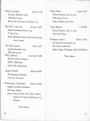
TRANSISTOR TESTER,Model 650 .....
$26.95
Beta Ranges: 0-10, 0-50, 0-250, (F.S.)
Beta Accuracy: ±3%, with 260 ±5% nominal
lea Range: 0- 100 ua
lea Accuracy: ± 1%, with 260 ± 3% (F.S.)
DC VTVM, Model 651.. . . . . .
AC AMMETER
MODEL 653
. $32.95
Voltage Ranges: 0-.5/1.0/2.5/5.0/10/25/50/100/
250/500
Accuracy: ± 1%, with 260 ± 3% (F.S.)
Input Impedance: greater than 10 megs all ranges
TEMPERATURE TESTER,Model 652 ... $38.95
Temperature R.anges: -50°F to +1000F,
+250°F
Accuracy: with 260 ±2° (nominal)
Three lead positions provided
Sensing Element: thermistor
+100°F
AC AMMETER, Model 653
to
$18.95
Ranges: 0-0.25/1/2.5/12.5/25
amps
Accuracy: ± 1 % with 260 ± 3 % nominal
Frequency Range: 50 cycles to 3000 cycles
t
AUDIO WATTMETER, Model 654. ..
. $18.95
Load Ranges: 4,8,16,600 ohms
Wattage: Continuous 25 watts (8,600 ohms)
50 watls (4,16 ohms)
Intermittent 50 watts (8,600 ohms)
100 watts (4,16 ohms)
Accuracy: ±5%, with 260 ±10% nominal
Direct reading scale from 17 microwatts to 100 watts
Just plug it in
MICROVOLT ATTENUATOR, Model 655. $18.95
Ranges: 2.5 microvolts to 250,000 microvolts
continuously variable in decade steps
Frequency: DC to 20 KC
Accuracy: ± 1db
BATTERY TESTER,Model 656.
$19.95
Checks all radio and hearing aid batteries up to 90
volts at the manufacturer's recommended load, or
any external load.
Note: All Simpson 260 Adopters provide for normal 260
usage without disconnecting the adapter.
IIMPIOR
ELECTRIC
COMPARY
5200 W. Kinale St.. Chlca90 44. IIUnola. ES 9-1121
In Ccmada.
Iach·Slm_n.
Ltd.. London. Ontario
Copyright 1959, Simpson Electric Co.
1-2.!5M-l0-!59
Printed in U.S.A.
OPERATOR'S MANUAL
SIMPSON AC AMMETER MODEL 653
SECTION I
GENERAL DESCRIPTION
INTRODUCTION
The Simpson AC Ammeter Adapter Model 653
a compact, accurate, wide-range instrument.
When it is used in conjunction with a Simpson
260* or 270 Multimeter, AC currents can be measured over a frequency range of 50 to 3000 cycles
per second. This wide frequency range in general
exceeds commercial and military power frequency
requirements.
IS
The Simpson YOM-plus-adapter concept
IS
completely unique in approach and versatility.
Each of the adapter models, of which the AC
Ammeter is but one example, provides specific
measurement and testing capabilities at a fraction
of the cost normally required for separate testers.
• Trade Mark Registered
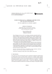
FIGURE
1 - SIMPSON AC AMMETER
MODEL
U. S. Patent Office
653
1
GENERAL DESCRIPTION
GENERAL DESCRIPTION
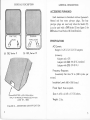
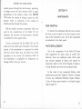
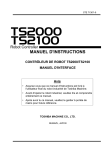
ACCESSORIES FURNISHED
Each instrument is furnished with an Operator's
Manual and four extra pin-type plugs. The four
pin-type plugs are used only when the Model 653
is to be used with a 260 Series II (see figure 2 for
260 Series II and Series III identification).
PIN
BANANA
TYPE
.4
.
TYPE
ACKS
(0) 260, Series II
\\
..
JACKS
II \\
(b) 260, Series III
SPECIFICATIONS
AC Current:
Ranges: 0-.25/1/2.5/12.5/25
amperes
Accuracy:
Adapter only ±2%
Adapter with 260 ±3% (F .S.) nominal
Adapter with 270 ±3% (F.S.)
Frequency Response:
Essentially flat from 50 to 3000 cycles per
second.
Insulation Level: 600 v RMS (max.)
Power Input: None required.
Size: 5-5/16 x 4-3/8 x 3-7/16 inches.
Weight: 2 lbs.
FIGURE 2 - 260 SERIES IDENTIFICATION
2
3
GENERAL DESCRIPTION
GENERAL DESCRIPTION
MODIFICATION
Adapter Case
260 - 653 SWITCH
KITS
Kit 401 for 260 Series
III and 270.
Use of this kit is optional. The kit converts
the 260 Series III or the 270 YOM produced prior
to June 1, 1959. It consists of a modified case
which permits latching the Model 653 securely to
the underside of the YOM.
Adapter Case Kit 402 for 260 Series
II.
Use of this kit is optional for this adapter. It
includes a modified case which permits lat7hing
the Model 653 securely to the underside of the
multimeter, and also provides a 50 pA D.C. current range for the 260. The 50 microampere range
is required for other Adapter Models.
This is a convenience switch located at the
right center of the front panel. It allows the use
of the YOM without detaching the Model 653.
260 DIRECT JACKS
The 260 DIRECT jacks are located at the left
center of the front panel. When the 260 DIRECT 653 ADAPTER switch is in the 260 DIRECT
position, these jacks are connected directly to the
260/270 input jacks marked + and COMMON
+,
SECTION II
OPERATING INSTRUCTIONS
CONTROLS AND CONNECTORS
BINDING POSTS
AC currents to be measured are applied to the
Model 653 through two of the six binding posts
located along the bottom of the front panel. One of
the binding posts (marked ±) is common for all
ranges. Each of the remaining five binding posts
represents a current range for the instrument.
4
.1.
Initial Adjustments
a.
260/270
control
settings.
1. With the Model 653 disconnected, check
the meter pointer position for zero indication with
the YOM in its operating position. If the pointer is
off zero, adjust the bake lite screw just under the
meter. Refer to the YOM Operator's Manual for this
adjustment.
5
OPERATING INSTRUCTIONS
]
OPERA TING INSTRUCTIONS
2. Set the '260/270 for AC operation.
3. Set the 2601270 range switch to the 2.5
volts position.
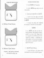
b. Connecting the Model 653 to the 260/270.
1. Insert the top four plugs of the Mode1
o
0-.0 0
O~
653 into the lower four jacks on the front panel of
the 260/270.
2. Position the locking latch underneath
the instrument to secure the two units together.
(a) 260 Series III Control Positions
CAUTION
If your 260/270 case does not have the
locking provision, avoid applying excessive
pressure to the top of the Adapter when
it is connected to the VOM and used in the
Adjust- A-Vue position. A modification kit
which includes a new case with an adapter
lock provision is recommended for optimum
rigidity (see page 4).
•
•
(b) 260 Series"
FIGURE
3 -
260 CONTROL
POSITIONS
FOR USE WITH MODEL
6
c. Model 653 Control Settings.
Control Positions
1. Set the 260 Direct - 653 Adapter switch
of the Model 653 to the 653 ADAPTER position.
653
7
OPERATING INSTRUCTIONS
OPERATING INSTRUCTIONS
2. Measuring A.C. Current
d. Record the 260/270 meter reading indicated
on the 2.5 V.A.C. scale.
WARNING
Always remove all power from the
to be tested before connecting
connecting the test leads, and
changing the range connections
leads.
circuit
or disbefore
of the
a. De-energize the circuit under test.
b. Connect a suitable lead from the ± binding
post on the Model 653 to one side of the circuit
under test.
c. Select a second binding post which will
provide a suitable current indication. When in
doubt as to the amount of current to be" measured,
use the 25A binding post first, and then change
to a lower range if the current is within the lower
range. Connect a suitable lead from this selected
binding post to the other side of the circuit under
test.
NOTE
The test leads and connections for steps
band c must be adequate for the circuit
under test. The test leads must have
ample current carrying capacity and each
connection must be tight and offer low
res istance.
8
e. Multiply the reading by the factor indicated
above the range binding post used.
3. Using the YOM circuit while the Model 653 is
attached.
a. Set the 260 Direct - 653 Adapter switch of
the Model 653 at its 260 DIRECT position.
b. Connect the regular VOM test leads to the
260 DIRECT jacks at the left side of the Model
653. Proceed with the standard operating instructions for the VOM, according to its Operator's
Manual.
SECTION III
THEORY OF OPERATION
GENERAL
The Model 653 AC Ammeter consists of a current transformer, an accurate load on the secondary and provisions for a voltmeter measurement
across the load. Any AC current through the primary is transformer-coupled to produce a proportional AC current in the secondary. The secondary
9
THEORY OF OPERATION
current passes through the load resistor, producing
a voltage across the load resistor which is again
proportional to the primary current. The 260/270
YOM reads the amount of voltage across the load
resistor which is indicative
of the amount of
current passing through the primary.
SECTION IV
MAINTENANCE
CASE REMOVAL
With the highly accurate components which are
used in the construction of the Model 653 AC
Ammeter, the accuracy of measurements obtained
is excellent for most applications.
Circuit connections for the Model 653 are the
same as for any other type of ammeter. The primary
circuit of the transformer is connected in .ser ie s
with the circuit under test, and offers very little
impedance in the circuit. The inductive effect of
the transformer is negligible for frequencies up
through 3000 cycles per second.
To remove the instrument from the case, remove
the four screws located in the four corners on the
back of the instrument case. All of the components
are attached to the front panel.
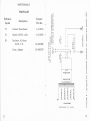
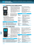
PARTS REPLACEMENT
All of the components of the Model 653 have
been engineered for many years of useful life.
However, there are conditions under which parts
may become damaged or faulty, and require replacement. Refer to the circuit diagram in figure 4
to help identify and locate any suspected part.
In the event of any component failure, order
replacement parts from Simpson Electric Company
or from any Authorized Warranty Repair Station.
A list of these repair stations is included, beginning on page 14.
10
11
MAINTENANCE
PARTS LIST
Reference
Symbol
Description
,,~
(\')
L{)
20
\D
Simpson
5">
zO
-1
Part No.
0""
Il.~
,f\"'b"
UI>3
Tl
Sl
R1
Current Transformer
Switch, DPDT, slide
Resistor, 4.0 ohms
±0.5%, 3 W.
Case, Adapter
1-118192
"
t-:.(
oSIV
uJ Iu <t
...•
\!l ol t-
z ~:)
10-860379
• °v
02
uO
0",
O'<lOLl.
10-805086
~
~'"
1-118211
WQ.(
oJ~
I-
V
I
V
tt--
Ow
Clef
N_
0
ci~
I"
o()~
W<l
~>
r-II\
(\jN
_0
01>3 •...
NuJ
III
~uJ
"+
's"
l\J
00
J
~I
v
tw
~
III
ef
tOol
W
0
0
:E
0::
W
l-
w
:E
~
<{
0
-c
Z
• +1
0
en
0..
~
Ill •...
en
\90<I
0
..
~
<{
0::
{9
<{
0
0
I<{
:E
W
I
0
en
1
<t
W
0::
:::>
A'ti'VVHl:Id
1;J3J.3~Wt-l
12
:)"I:f
{9
-L()dNI
LL
13
•
SIMPSON WARRANTY
REPAIR STATIONS
AND PARTS DEPOTS
*California, Los Angeles
ADams 2-4201
Quality Electric Company
3700 South Broadway
States: So. California below Fresno and Arizona
*California, San Francisco
Pacific Electrical
111 Main Street
GArfield 1-7185
Instrument Lab.
States: No. California above Fresno and Nevada
Canada
Bach-Simpson Ltd.
1255 Brydges Street
P.O. Box 484
London, Ontario, Canada
GLadstone 1-9490
*Louisiana, New Orleans
TWinbrook 5-5621
Industrial Instrument Works
3328 Magazine Street
States: Arkansas, Mississippi and Louisiana
*Massachusetts, Cambridge
UNiversity 4-2494
Alvin C. Mancib Company
363 Walden Street
States: Vermont, New Hampshire, Massachusetts,
Connecticut, Rhode Island and Maine
Lincoln 7-1000
*Michigan, Detroit
*Colorado, Denver
RAce 2-8670
Meter-Master Instrument Service
2379 Downing Street
States: Wyoming, Utah, Colo. and New Mexico
*Georgia, Atlanta
*Illinois, Chicago
COlumbus 1-1330
Pacific Indicator Company
5217 W. Madison Street
States: Chicago, Wisconsin and Indiana
PLaza 3-4128
Electro- Tech Equipment
690 Murphy Avenue S. W.
States: Alabama, Georgia, Florida,
No. & So. Carolina, and Tenn.
Ram Meter, Inc.
1100 Hilton Road, Ferndale
States: Michigan
*Minnesota, Minneapolis
KEllogg 7-5411
Instrumentation Services
917 Plymouth Avenue
States: Minnesota, North and South Dakota
*Missouri, St. Louis
FOrest 7-9799
Scherrer Instruments
5449 Delmar Blvd.
States: Illinois below Peoria, Iowa, Missouri,
and Kansas
*Parts Depots
14
*Parts Depots
15
*New York, Buffalo
EXport 2-2726
Electrical Instrument Labs.
1487 Hertal Avenue
States: New York State except Met. N. Y.
*New York 7, New York
BArclay 7-4977
Simpson Instrument Service Corp.
27 Park Place
States: Metropolitan New York and New Jersey,
above Trenton
New York, Syracuse
HYatt 2-1651
Syracuse Instrument Lab.
2904 South Avenue
*Ohio, Cleveland
CLearwater 1-4609
Weschler Electric Company
4250 W. BOth Street
States: Ohio and Kentucky
Oregon, Portland
The Instrument Laboratory
1316 S. E. 7th Avenue
*Texas, Dallas
TAylor 4-2626
Nelson Electronic Eng. Co.,. Inc.
6329 Gaston Avenue
States: Oklahoma and Texas
Texas, Houston
Nelson Electronic Eng. Co,; Inc.
3615 Gulf Freeway
CA 8-2835
*Washington, Seattle
ATwater 3-5850
The Instrument Laboratory, Inc.
934 Elliott Avenue West
States: Oregon, Washington, Idaho and Montana
*Parts Depots
BElmont 4-6683
*Pennsylvania, Philadelphia
ORchard 3-5600
Sunshine Scientific Instrument
1810 Grant Avenue
States: Penn. Md. New Jersey below Trenton,
Virginia, W. Virginia, Washington, D.C.,
Delaware
*Parts Depots
16
17
'e
/I
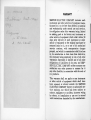
WARRANTY
c:fJ~
dLu.L / ~
/979_
r~~/
/_
(
/1'
...0
i,
CELL-
d _ A A - C e: LLS,
SIMPSON ELECTRIC COMPANY warrants each
instrument and other article s of equipment manufactured by it to be free from defects in material
and workmanship under normal use and service,
its obligation under this warranty being limited
to making good at its factory any instrument or
other article of equipment which shall within 90
days after delivery of such instrument or other
article of equipment to the original purchaser be
returned intact to it, or to one of its authorized
service stations,
with transportation
charges
prepaid, and which its examination shall disclose
to its satisfaction to have been thus defective;
this warranty being expressly in lieu of all other
warranties expressed or implied and of all other
obligations or liabilities on its part, and SIMPSON ELECTRIC COMPANY neither assumes nor
authorizes any other persons to assume for it
any other liability in connection with the sale of
its products.
This warranty shall not apply to any instrument
or other article of equipment which shan have
been repaired or altered outside the SIMPSON
ELECTRIC COMPANY factory or authorized service stations, nor which has been subject to
misuse, negligence or accident, incorrect wiring
,by others, or instaliation or use not in accord
with instructions furnished by the manufacturer.