1
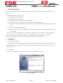
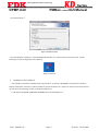
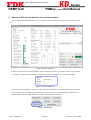
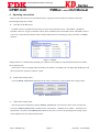
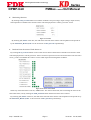
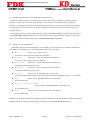
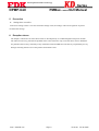
Delivering Next Generation Technology Series PMBus control GUI Manual DPMP-GUI 1/16Brick DC-DC Power module KD series (Full digital) GUI for PMBusTM control User’s manual Version 01.01 Jan. 20, 2015 Delivering Next Generation Technology DPMP-GUI Series PMBus control GUI Manual 1. Product overview ........................................................................................................................................... 2 2. Installation ..................................................................................................................................................... 2 a. Operation environment .............................................................................................................................. 2 b. Install ......................................................................................................................................................... 2 c. Install of USB driver .................................................................................................................................. 3 3. Startup of GUI and perception of connected module .................................................................................... 4 4. Operating instructions.................................................................................................................................... 5 a. KD series ON/OFF .................................................................................................................................... 5 b. Read of the setting value............................................................................................................................ 5 c. Write of the setting value ........................................................................................................................... 5 d. Various monitor ......................................................................................................................................... 6 e. Read and clear of the status of fault alarm etc.. ......................................................................................... 6 f. Settings of ON_OFF_CONFIG, fault response ......................................................................................... 7 g. Settings value and store/restore of non-volatile memory........................................................................... 8 h. Settings etc. via command line .................................................................................................................. 8 5. Precaution ...................................................................................................................................................... 9 a. 6. Settings does not reflect. ............................................................................................................................ 9 Exception clause ............................................................................................................................................ 9 http://www.fdk.com Page 1 Ver 01.01 Jan 20, 2015 Delivering Next Generation Technology DPMP-GUI 1. Series PMBus control GUI Manual Product overview This product is a GUI for the PC to control 1/16Brick DC-DC power module of KD series via a PMBusTM interface. The loaded functions are shown below. Detect the connected modules Write/Read of various settings Monitor the status of voltages, current, temperature etc. Monitor or clear the fault alarm status of voltages, current, temperature etc. Write data to nonvolatile memories or copy the data from nonvolatile memories to the operating storage area. Reset to the factory (default) settings. Polling function which is use to periodically monitor status, voltages, current and temperature of the power module. KD series is compliant with PMBusTM1.2 specification, detailed settings of voltages, current, temperature etc. and a monitoring function are available. Please refer to PMBus_Specification published by the System Management Interface Forum for further details (Some commands are not supported) 2. Installation a. Operation environment This software is only tested for operation with 32 bits OS of Windows XP/Vista/7. So please used a PC with the supported OS (Note that the 64 bits version is not supported), and also Microsoft .NET Framework4.0 or about is required. b. Installation Execute setup.exe and the following screen will be shown automatically. Click Next↓ Figure 1 Installer http://www.fdk.com Page 2 Ver 01.01 Jan 20, 2015 Delivering Next Generation Technology Series PMBus control GUI Manual DPMP-GUI Click Install button↓ Figure 2 Install execution After finishing the installation, “Launch DpmPmbusWindow.exe” will be shown on the start menu, and the following icon will be displayed on the desktop. Figure 3 GUI icon c. Installation of the USB driver The USB driver should be installed before using the GUI. To install, USB-PMBus communication interface adaptor (hereinafter referred to as UPIA) should be connected with the PC. The driver install screen will be started up, and select the following location to install the USB driver. “C:¥Program Files¥FDK CORPORATION¥KD Series Software¥Drivers” http://www.fdk.com Page 3 Ver 01.01 Jan 20, 2015 Delivering Next Generation Technology DPMP-GUI Series PMBus control GUI Manual 3. Startup of GUI and the detection of connected module Select “Launch DpmPmbusWindow.exe” on the Start menu to startup the GUI. Below is the full view of the GUI. Figure 4 Full view of the GUI In order to recognize the connected modules, please make sure that the PC, the UPIA and the power module are properly connected. The “MODULE” column on the GUI will display every connected modules. Figure 5 Detection of KD series Please confirm the modules recognition is right. And, the tab windows on the GUI will increase in response to the number of power modules are being detected. Also, the startup of the GUI without connected to any module should click the SEEK_MODULE to detect connected power modules. Figure 6 SEEK button http://www.fdk.com Page 4 Ver 01.01 Jan 20, 2015 Delivering Next Generation Technology Series PMBus control GUI Manual DPMP-GUI 4. Operating instructions Details of the GUI functions are described as below. Operation must be under the condition of the GUI acknowledged the power module. a. ON/OFF of the KD series ON/OFF control is available from the GUI, by select of the pull-down menu ”SETTINGS”_MODULE ON/OFF。There are 2 types of ON/OFF control, which are RMT control and CMD control. The RMT control is a DC level control directly from the UPIA, and the CMD control is controlling by a host controller via PMBus interface. Figure 7 ON/OFF CMD_OFF/ON is available under the RMT_ON condition. The CMD_ON will be disabled when off condition cause by RMT_OFF. If the devise is off even though under the CMD_ON condition, turn RMT_ON CMD_OFFCMD_ON and then reconfirm the operation condition is good. b. Read of the setting values Click the READ_SETTINGS button that the PC able to monitor the connected KD series setting values. Figure 8 READ/WRITE/STATUS c. Write of the setting value The settings will be changed by clicking WRITE_SETTINGS. Overwrite the values on the GUI after the execution of READ_SETTINGS (available frame: “SETTINGS”, “WARN/FAULT LIMIT”,”OPTION AND RESPONSE”) and then click WRITE_SETTINGS on the GUI, you can write and change the settings of the connected KD series for required specification. http://www.fdk.com Page 5 Ver 01.01 Jan 20, 2015 Delivering Next Generation Technology Series PMBus control GUI Manual DPMP-GUI d. Monitoring functions By clicking GET_STATUS button can read the conditions of input voltage, output voltage, output current, and temperature of the KD series and the values will be displayed in the “READ_VALUES” frame. Figure 9 VALUES By checking (✔) POLL check box, the read status and read values frames will be updated on the period set by the POLLING_RATE (POLL is the execution of GET_STATUS periodically) e. Read and clear the status of fault alarms etc.. By clicking GET_STATUS button can also read various status of fault alarm of the KD series and the values will be displayed in the “READ_STATUS” frame. Green box represent error free and if the fault occurred it turns red. E.g. VIN OV WARN/FAULT have 2 boxes which represent Warning/Fault condition. Figure 10 STATUS and CLEAR When any of the fault alarm occurred, “SMBALART” box will be turned red, after confirming the cause of the fault status alarm, and by clicking CLEAR_FAULTS button fault status alarm can be cleared. By checking (✔) POLL check box, the read status and read values frames will be updated on the period set by the POLLING_RATE (POLL is the execution of GET_STATUS periodically). http://www.fdk.com Page 6 Ver 01.01 Jan 20, 2015 Delivering Next Generation Technology Series PMBus control GUI Manual DPMP-GUI f. Settings of ON_OFF_CONFIG, fault response The five LSB bits of the PMBus interface ON_OFF_CONFIG(02h) command can be set from the ON/OFF_OPTIONS on the “OPTION AND RESPONSE” frame. Figure 11 ON_OFF_CONFIG Output Margin-H/L, stop can be selected. (PMBus: OPERATION (01h)[5:4]) Figure 12 MGNLH Settings of fault responses (Immediate shuts down, continue operation, Hiccup etc.) of fault conditions are available. The way of settings is to select through the separated column in “OPTION AND RESPONSE” frame. Pull-down menu from left RSP: shuts down or continue etc. basic settings, RS: restart settings, DT: delay time settings are available. Detailed operation of the settings please refer to the KD series specification. Figure 13 Fault response http://www.fdk.com Page 7 Ver 01.01 Jan 20, 2015 Delivering Next Generation Technology Series PMBus control GUI Manual DPMP-GUI g. Settings value and store/restore of the non-volatile memory The KD series has built-in a non-volatile memory and be able to store the setting values of the operating memory in used. On the other hand, stored data also can be moved to the operating memory. With these functions, set condition which has been changed during the evaluation can be saved. Call out the saved settings soon after power on can save time to set up again. Furthermore, Initialize to the factory (default) settings can easily be done too. Setting data can be store to non-volatile memory by using the STORE_USER command. On the other hand, a click of RESTORE_USER enable the data on non-volatile memory copy to operating memory for use. If you like to reset to factory (default) settings just click RESTORE_DEFAULTS button. h. Settings etc. via command line Read/Write settings via the command line is also available. It can be used to set/get multiple commands at a time. Below is an example (% is a command prompt which is not a user input) :Send % 03 w byte: Send byte 03h (Send byte is the write process without any write data) :Write byte: Write data 80h with command 01h % 01 w 80 (Write byte is the write process with a data byte) % 35 w 34.625 :Write word: Write 34.625[V] with command 35h (Voltages threshold setting unit is [V]) % 46 w 12.25 :Write word: Write 12.25[A] with command 46h (Currents threshold setting unit is [A]) :Write word: Write 90[℃] with command 53h % 53 w 90 (Temperatures threshold setting unit is [℃], after the decimal point is disapprove and “-” is available) :Read % 01 r word: Read data from with command 01h (Use for Word read) % 9A w fpkd48t01208Pa :Write block: Write fpkd48t01208Pa to the address 9Ah (Use for Block write) % 9A r :Read block: Read data from with command 9Ah (Use for Block read) Prepare a set of multiple settings in a test file, copy them and paste it into the command window, the required commands can be set. Please reconfirmed the settings by clicking READ_SETTINGS button. http://www.fdk.com Page 8 Ver 01.01 Jan 20, 2015 Delivering Next Generation Technology DPMP-GUI Series PMBus control GUI Manual 5. Precaution a. Settings does not reflect. If the write settings values is over the maximum settings value, the settings value will be ignored. So please reconfirm the settings. 6. Exception clause The adaptor, software driver and software tools are developed only to evaluated digital brick power module. The software tools may periodical be updated and in some situation it may not be the latest version. FDK does not guarantee the accuracy and safety of any information and also FDK does not take any responsibility for any damages resulting from the use of this product and software tools. http://www.fdk.com Page 9 Ver 01.01 Jan 20, 2015