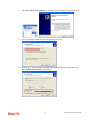
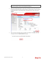
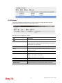
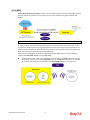
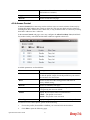
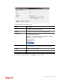
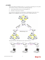
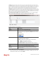
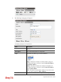
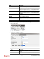
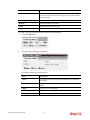
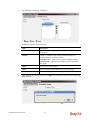
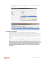
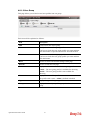
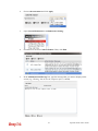
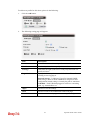
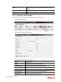
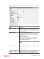
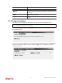
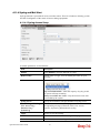
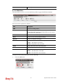
1
Vigor2760 Series
High Speed VDSL2 Router
User’s Guide
Version: 1.0
Firmware Version: V1.0.0_RC14
(For future update, contact DrayTek)
Date: 14/12/2012
ii
Vigor2760 Series User’s Guide
Copyright Information
Copyright
Declarations
Copyright 2012 All rights reserved. This publication contains information that is
protected by copyright. No part may be reproduced, transmitted, transcribed, stored in a
retrieval system, or translated into any language without written permission from the
copyright holders.
Trademarks
The following trademarks are used in this document:
z
Microsoft is a registered trademark of Microsoft Corp.
z
Windows, Windows 95, 98, Me, NT, 2000, XP, Vista and Explorer are
trademarks of Microsoft Corp.
z
Apple and Mac OS are registered trademarks of Apple Inc.
z
Other products may be trademarks or registered trademarks of their respective
manufacturers.
Safety Instructions and Approval
Safety
Instructions
Warranty
z
z
Read the installation guide thoroughly before you set up the router.
The router is a complicated electronic unit that may be repaired only be
authorized and qualified personnel. Do not try to open or repair the router
yourself.
z
Do not place the router in a damp or humid place, e.g. a bathroom.
z
The router should be used in a sheltered area, within a temperature range of +5 to
+40 Celsius.
z
Do not expose the router to direct sunlight or other heat sources. The housing and
electronic components may be damaged by direct sunlight or heat sources.
z
Do not deploy the cable for LAN connection outdoor to prevent electronic shock
hazards.
z
Keep the package out of reach of children.
z
When you want to dispose of the router, please follow local regulations on
conservation of the environment.
We warrant to the original end user (purchaser) that the router will be free from any
defects in workmanship or materials for a period of two (2) years from the date of
purchase from the dealer. Please keep your purchase receipt in a safe place as it serves
as proof of date of purchase. During the warranty period, and upon proof of purchase,
should the product have indications of failure due to faulty workmanship and/or
materials, we will, at our discretion, repair or replace the defective products or
components, without charge for either parts or labor, to whatever extent we deem
necessary tore-store the product to proper operating condition. Any replacement will
consist of a new or re-manufactured functionally equivalent product of equal value, and
will be offered solely at our discretion. This warranty will not apply if the product is
modified, misused, tampered with, damaged by an act of God, or subjected to abnormal
working conditions. The warranty does not cover the bundled or licensed software of
other vendors. Defects which do not significantly affect the usability of the product will
not be covered by the warranty. We reserve the right to revise the manual and online
documentation and to make changes from time to time in the contents hereof without
obligation to notify any person of such revision or changes.
Be a Registered
Owner
Web registration is preferred. You can register your Vigor router via
http://www.draytek.com.
Firmware & Tools
Updates
Due to the continuous evolution of DrayTek technology, all routers will be regularly
upgraded. Please consult the DrayTek web site for more information on newest
firmware, tools and documents.
http://www.draytek.com
Vigor2760 Series User’s Guide
iii
European Community Declarations
Manufacturer:
Address:
Product:
DrayTek Corp.
No. 26, Fu Shing Road, HuKou County, HsinChu Industrial Park, Hsin-Chu, Taiwan 303
Vigor2760 Series Router
DrayTek Corp. declares that Vigor2760 Series of routers are in compliance with the following essential
requirements and other relevant provisions of R&TTE Directive 1999/5/EEC.
The product conforms to the requirements of Electro-Magnetic Compatibility (EMC) Directive 2004/108/EC by
complying with the requirements set forth in EN55022/Class B and EN55024/Class B.
The product conforms to the requirements of Low Voltage (LVD) Directive 2006/95/EC by complying with the
requirements set forth in EN60950-1.
Regulatory Information
Federal Communication Commission Interference Statement
This equipment has been tested and found to comply with the limits for a Class B digital device, pursuant to Part
15 of the FCC Rules. These limits are designed to provide reasonable protection against harmful interference in a
residential installation. This equipment generates, uses and can radiate radio frequency energy and, if not installed
and used in accordance with the instructions, may cause harmful interference to radio communications. However,
there is no guarantee that interference will not occur in a particular installation. If this equipment does cause
harmful interference to radio or television reception, which can be determined by turning the equipment off and
on, the use is encouraged to try to correct the interference by one of the following measures:
z
Reorient or relocate the receiving antenna.
z
Increase the separation between the equipment and receiver.
z
Connect the equipment into an outlet on a circuit different form that to which the receiver is connected.
z
Consult the dealer or an experienced radio/TV technician for help.
This device complies with Part 15 of the FCC Rules. Operation is subject to the following two conditions:
(1) This device may not cause harmful interference, and
(2) This device may accept any interference received, including interference that may cause undesired operation.
Please visit http://www.draytek.com/user/SupportDLRTTECE.php#
This product is designed for POTS, DSL, 2.4GHz WLAN network throughout the EC region and Switzerland
with restrictions in France. Please see the user manual for the applicable networks on your product.
iv
Vigor2760 Series User’s Guide
Table of Contents
Introduction ..........................................................................................................1
1.1 Web Configuration Buttons Explanation ................................................................................. 1
1.2 LED Indicators and Connectors .............................................................................................. 2
1.1.1 For Vigor2760 ................................................................................................................... 2
1.1.2 For Vigor2760n ................................................................................................................. 4
1.1.3 For Vigor2760Vn............................................................................................................... 6
1.3 Hardware Installation .............................................................................................................. 8
1.4 Printer Installation ................................................................................................................... 9
Initial Configuration ...........................................................................................15
2.1 Accessing Web Page ............................................................................................................ 15
2.2 Quick Start Wizard for Connecting Internet........................................................................... 16
2.3 Dashboard for System Status ............................................................................................... 21
2.4 Quick Access for Common Used Menu ................................................................................ 22
Applications and Tutorials ................................................................................23
3.1 Registering the Router for Getting Relational Information in the Future............................... 23
3.2 Activating Web Content Filter Mechanism ............................................................................ 26
3.2.1 By Means of Service Activation ...................................................................................... 26
3.2.2 By Means of MyVigor Website ....................................................................................... 31
Advanced Web Configuration...................................................................................35
4.1 Network ................................................................................................................................. 35
4.1.1 WAN................................................................................................................................ 36
4.1.1.1 Basics of Internet Protocol (IP) Network.............................................................. 36
4.1.1.2 What are Public IP Address and Private IP Address........................................... 36
4.1.1.3 Get Your Public IP Address from ISP.................................................................. 36
4.1.1.4 Network Connection by 3G USB Modem ............................................................ 36
4.1.1.5 Several Connection Protocols Used for the Router............................................. 37
4.1.1.6 WAN Status ......................................................................................................... 38
4.1.1.7 WAN DSL ............................................................................................................ 39
4.1.1.8 WAN Bridge ......................................................................................................... 43
4.1.1.9 WAN USB ............................................................................................................ 46
4.1.1.10 WAN DSL Mode ................................................................................................ 48
4.1.2 LAN ................................................................................................................................. 49
4.1.2.1 Basics of LAN ...................................................................................................... 49
4.1.2.2 What is Routing Information Protocol (RIP)......................................................... 49
4.1.2.3 What is Static Route ............................................................................................ 49
Vigor2760 Series User’s Guide
v
4.1.2.4 LAN Status........................................................................................................... 50
4.1.2.5 Ethernet ............................................................................................................... 50
4.1.3 NAT................................................................................................................................. 53
4.1.4 DHCP.............................................................................................................................. 57
4.1.5 Static Route .................................................................................................................... 60
4.1.5.1 Static Default Route............................................................................................. 60
4.1.5.2 Static Route ......................................................................................................... 61
4.1.6 Dynamic Route ............................................................................................................... 63
4.1.7 DNS ................................................................................................................................ 64
4.1.7.1 DNS Status .......................................................................................................... 64
4.1.7.2 DNS Setting ......................................................................................................... 65
4.1.8 Quality of Service............................................................................................................ 65
4.1.9 Failover ........................................................................................................................... 68
4.1.10 Switch ........................................................................................................................... 70
4.1.10.1 Switch ................................................................................................................ 70
4.1.10.2 Port Mirror.......................................................................................................... 72
4.2 Wireless LAN ........................................................................................................................ 73
4.2.1 Basic Concepts............................................................................................................... 73
4.2.1.1 Security Setting Overview.................................................................................... 73
4.2.2 General Setup................................................................................................................. 74
4.2.3 WPS................................................................................................................................ 79
4.2.4 Access Control................................................................................................................ 81
4.2.5 WDS................................................................................................................................ 83
4.2.6 WMM............................................................................................................................... 87
4.2.7 AP Discovery .................................................................................................................. 89
4.2.7.1 AP List.................................................................................................................. 89
4.2.7.2 Channel Statistics ................................................................................................ 90
4.2.8 Station List ...................................................................................................................... 90
4.3 Firewall .................................................................................................................................. 92
4.3.1 Basics for Firewall........................................................................................................... 92
4.3.1.1 Denial of Service (DoS) Defense......................................................................... 92
4.3.2 Filter Setup ..................................................................................................................... 92
4.3.2.1 Filter Rule ............................................................................................................ 92
4.3.2.2 Default Rule ......................................................................................................... 97
4.3.3 DoS Defence .................................................................................................................. 98
4.4 Objects Setting.................................................................................................................... 101
4.4.1 Address......................................................................................................................... 101
4.4.1.1 Address Object .................................................................................................. 101
4.4.1.2 Address Group................................................................................................... 105
4.4.2 Service Type................................................................................................................. 107
4.4.2.1 Service Type Object .......................................................................................... 107
4.4.2.2 Service Type Group........................................................................................... 110
4.4.3 Keyword ........................................................................................................................ 112
4.4.3.1 Keyword Object ................................................................................................. 112
4.4.3.2 Keyword Group.................................................................................................. 114
4.4.3.3 Default Keyword Object / Group........................................................................ 116
4.4.4 Schedule ....................................................................................................................... 117
4.4.4.1 Schedule Object ................................................................................................ 117
4.4.4.2 Schedule Group................................................................................................. 120
4.5 CSM .................................................................................................................................... 122
4.5.1 Application Filter ........................................................................................................... 122
4.5.2 URL Content Filter ........................................................................................................ 124
4.5.3 Web Content Filter........................................................................................................ 128
4.5.3.1 Web Content Filter............................................................................................. 129
4.5.3.2 Advanced........................................................................................................... 132
4.6 User Management............................................................................................................... 133
vi
Vigor2760 Series User’s Guide
4.6.1 User Profile ................................................................................................................... 133
4.6.1.1 User Object........................................................................................................ 134
4.6.1.2 User Group ........................................................................................................ 137
4.6.2 RADIUS ........................................................................................................................ 140
4.6.3 Privilege ........................................................................................................................ 142
4.6.4 Advertisement............................................................................................................... 145
4.6.4.1 Example for Advertisement ............................................................................... 145
4.7 Applications ......................................................................................................................... 147
4.7.1 Local DNS..................................................................................................................... 147
4.7.1.1 Service ............................................................................................................... 147
4.7.1.2 Advanced........................................................................................................... 150
4.7.2 Dynamic DNS ............................................................................................................... 151
4.7.2.1 Status................................................................................................................. 151
4.7.2.2 Service ............................................................................................................... 152
4.7.2.3 Advanced........................................................................................................... 155
4.7.3 UPnP............................................................................................................................. 156
4.7.4 IGMP............................................................................................................................. 158
4.8 USB Applications................................................................................................................. 159
4.8.1 USB Status ................................................................................................................... 159
4.8.1.1 Disk Status......................................................................................................... 160
4.8.1.2 Printer Status ..................................................................................................... 160
4.8.2 SAMBA ......................................................................................................................... 161
4.8.2.1 Disk Share ......................................................................................................... 161
4.8.2.1 General .............................................................................................................. 164
4.8.3 FTP Server ................................................................................................................... 165
4.8.3.1 FTP User ........................................................................................................... 165
4.8.3.2 General .............................................................................................................. 167
4.9 VPN and Remote Access.................................................................................................... 168
4.9.1 Service Control ............................................................................................................. 168
4.9.2 LAN to LAN................................................................................................................... 169
4.9.3 Remote Dial-in User ..................................................................................................... 176
4.9.4 Status............................................................................................................................ 181
4.10 Certificate Management .................................................................................................... 182
4.10.1 Local Certificate .......................................................................................................... 182
4.10.1.1 Generate Local Certificate............................................................................... 183
4.10.1.2 Upload Local Certificate................................................................................... 186
4.10.2 Remote Certificate ...................................................................................................... 188
4.10.3 Trusted CA Certificate ................................................................................................ 190
4.10.4 Certificate Revocation List.......................................................................................... 192
4.11 System Maintenance......................................................................................................... 193
4.11.1 TR-069 ........................................................................................................................ 193
4.11.2 Administrator Setting .................................................................................................. 195
4.11.3Configuration Backup .................................................................................................. 196
4.11.4 Syslog and Mail Alert .................................................................................................. 197
4.11.4.1 Syslog Access Setup ....................................................................................... 197
4.11.4.2 Mail Alert.......................................................................................................... 198
4.11.5 Time and Date ............................................................................................................ 200
4.11.6 Management............................................................................................................... 201
4.11.7 SNMP.......................................................................................................................... 202
4.11.8 Reboot System ........................................................................................................... 205
4.11.9 Firmware Upgrade ...................................................................................................... 205
4.11.10 Activation .................................................................................................................. 206
4.12 Diagnostics........................................................................................................................ 207
4.12.1 Routing Table ............................................................................................................. 207
Vigor2760 Series User’s Guide
vii
4.12.2 ARP Cache Table ....................................................................................................... 207
4.12.3 DHCP Table................................................................................................................ 208
4.12.4 Data Flow Monitor....................................................................................................... 208
4.12.5 System Table.............................................................................................................. 209
4.12.6 Traffic Graph............................................................................................................... 211
4.12.7 Web Syslog................................................................................................................. 212
Trouble Shooting ............................................................................................213
5.1 Checking If the Hardware Status Is OK or Not.................................................................... 213
5.2 Checking If the Network Connection Settings on Your Computer Is OK or Not ................. 214
For Windows .................................................................................................................. 214
For Mac OS.................................................................................................................... 215
5.3 Pinging the Router from Your Computer ............................................................................. 216
For Windows .................................................................................................................. 216
For Mac OS (Terminal) .................................................................................................. 216
5.4 Checking If the ISP Settings are OK or Not ........................................................................ 217
5.5 Backing to Factory Default Setting If Necessary ................................................................ 218
Software Reset .............................................................................................................. 218
Hardware Reset............................................................................................................. 218
5.6 Contacting Your Dealer ....................................................................................................... 219
viii
Vigor2760 Series User’s Guide
Introduction
The Vigor2760 series are the routers with high speed in data transmission through DSL port
and LAN ports.
With the development of NGN (Next Generation Network), you may recently hear the news
about FTTx deployment in your local area or even have already subscribed the unbundling last
mile service (e.g. VDSL2) from local ITSP for FTTx. As adopting FTTx, the main question
for end users is whether your legacy router could fully utilize its bandwidth or not.
DrayTek launches Vigor 2760 series – High speed router, perfectly complied with VDSL2
environment including Vigor2760, Vigor2760n and Vigor2760Vn for speed-wanted customers.
With high throughput performance and secured broadband connectivity provided by Vigor
2760 series, you can simultaneously engage these bandwidth-intensive applications, such as
high-definition video streaming, online gaming, and Internet telephony / access..
1.1 Web Configuration Buttons Explanation
Several main buttons appeared on the web pages are defined as the following:
Save and apply current settings.
Cancel current settings and recover to the previous saved settings.
Clear all the selections and parameters settings, including selection from
drop-down list. All the values must be reset with factory default settings.
Add new settings for specified item.
Edit the settings for the selected item.
Delete the selected item with the corresponding settings.
Note: For the other buttons shown on the web pages, please refer to Chapter 4 for detailed
explanation.
Vigor2760 Series User’s Guide
1
1.2 LED Indicators and Connectors
Before you use the Vigor router, please get acquainted with the LED indicators and connectors
first.
1.1.1 For Vigor2760
LED
(ACT)
DSL (Green)
Status
Explanation
Blinking
The router is powered on and running normally.
Off
The router is powered off.
On
The DSL port is connected.
Blinking
(Slowly)
Blinking
(Quickly)
The router is ready.
On (Green)
The port is connected.
Blinking
(Green)
The data is transmitting.
On
A USB device is connected and active.
The connection is training.
~
LAN1/2/3/4
~
USB1/2
2
Vigor2760 Series User’s Guide
Interface
PWR
I/O
Description
Connector for a power adapter.
Power switch.
Factory Reset
Restore the default settings. Usage: Turn on the router (ACT LED is
blinking). Press the hole and keep for more than 5 seconds. When you
see the ACT LED begins to blink rapidly than usual, release the button.
Then the router will restart with the factory default configuration.
Connector for accessing the Internet.
Connector for USB storage device (Pen Driver/Mobile HD) or printer or
3G backup.
Connectors for local network devices.
VDSL/ADSL
USB (1-2)
LAN (1-4)
Vigor2760 Series User’s Guide
3
1.1.2 For Vigor2760n
LED
(Activity)
(Wireless LAN
On/Off/WPS)
DSL (Green)
~
LAN1/2/3/4
~
Status
Explanation
Blinking
The router is powered on and running normally.
Off
The router is powered off.
On (Green)
The wireless access point is ready.
Blinking
(Green)
Blinking
(Orange)
The data is transmitting via wireless connection.
Off
The wireless access point is turned off.
On
The DSL port is connected.
Blinking
(Slowly)
Blinking
(Quickly)
The router is ready.
On
The port is connected.
Blinking
(Green)
The data is transmitting.
On
A USB device is connected and active.
Blinks with one second cycle for two minutes. The WPS
function is active.
The router is trying to connect to Internet.
USB1/2
4
Vigor2760 Series User’s Guide
Interface
Description
PWR
Connector for a power adapter.
I/O
Power switch.
Factory Reset
Restore the default settings. Usage: Turn on the router (ACT LED is
blinking). Press the hole and keep for more than 5 seconds. When you see
the ACT LED begins to blink rapidly than usual, release the button. Then
the router will restart with the factory default configuration.
WLAN
ON/OFF/WPS
WLAN WPS - Press this button for 2 seconds to wait for client device making
network connection through WPS. When the LED lights up, the WPS connection
will be on.
WLAN ON/OFF - Press the button once to enable (WLAN LED on) or disable
(WLAN LED off) wireless connection.
VDSL/ADSL
Connector for accessing the Internet.
USB (1-2)
Connector for USB storage device (Pen Driver/Mobile HD) or printer or
3G backup.
LAN (1-4)
Connectors for local network devices.
Vigor2760 Series User’s Guide
5
1.1.3 For Vigor2760Vn
LED
Status
Blinking
Explanation
The router is powered on and running normally.
Off
The router is powered off.
On
Off
A PSTN phone call comes (in and out). However, when
the phone call is disconnected, the LED will be off for
awhile.
There is no PSTN phone call.
On
The phone connected to this port is off-hook.
Off
The phone connected to this port is on-hook.
Blinking
A phone call comes.
On (Green)
The wireless access point is ready.
Blinking
(Green)
Blinking
(Orange)
Off
The data is transmitting via wireless connection.
On
The DSL port is connected.
Blinking
(Slowly)
The router is ready.
Blinking
(Quickly)
The router is trying to connect to Internet.
On
The port is connected.
Blinking
(Green)
The data is transmitting.
On
A USB device is connected and active.
(ACT)
(LINE)
(Phone1/Phone2)
(Wireless LAN
On/Off/WPS)
DSL (Green)
~
LAN1/2/3/4
~
Blinks with one second cycle for two minutes. The WPS
function is active.
The wireless access point is turned off.
USB1/2
6
Vigor2760 Series User’s Guide
Interface
PWR
I/O
Description
Connector for a power adapter.
Power switch.
Factory Reset
Restore the default settings. Usage: Turn on the router (ACT LED is
blinking). Press the hole and keep for more than 5 seconds. When you
see the ACT LED begins to blink rapidly than usual, release the button.
Then the router will restart with the factory default configuration.
WLAN WPS - Press this button for 2 seconds to wait for client device making
WLAN
ON/OFF/WPS
VDSL/ADSL
USB (1-2)
network connection through WPS. When the LED lights up, the WPS
connection will be on.
WLAN ON/OFF - Press the button once to enable (WLAN LED on) or disable
(WLAN LED off) wireless connection.
LAN (1-4)
Connector for accessing the Internet.
Connector for USB storage device (Pen Driver/Mobile HD) or printer or
3G backup.
Connectors for local network devices.
Interface
LINE
Phone1/Phone2
Description
Connector for PSTN life line.
Connector of analog phone for VoIP communication.
Vigor2760 Series User’s Guide
7
1.3 Hardware Installation
Before starting to configure the router, you have to connect your devices correctly.
1.
Connect the XDSL interface to the external XDSL splitter with an XDSL line cable for
all models. For Vigor2760Vn, also connect Line interface to external XDSL splitter.
2.
Connect one port of 4-port switch to your computer with a RJ-45 cable. This device
allows you to connect 4 PCs directly.
3.
Connect Phone port to a conventional analog telephone (for V model only).
4.
Connect detachable antennas to the router for Vigor2760 series (for n model only).
5.
Connect one end of the power cord to the power port of this device. Connect the other
end to the wall outlet of electricity.
6.
Power on the router.
7.
Check the ACT and DSL, LAN LEDs to assure network connection.
(For the detailed information of LED status, please refer to section 1.2.)
8
Vigor2760 Series User’s Guide
1.4 Printer Installation
You can install a printer onto the router for sharing printing. All the PCs connected this router
can print documents via the router. The example provided here is made based on Windows
XP/2000. For Windows 98/SE/Vista, please visit www.draytek.com.
Before using it, please follow the steps below to configure settings for connected computers
(or wireless clients).
1.
Connect the printer with the router through USB/parallel port.
2.
Open Start->Settings-> Printer and Faxes.
Vigor2760 Series User’s Guide
9
3.
Open File->Add a New Computer. A welcome dialog will appear. Please click Next.
4.
Click Local printer attached to this computer and click Next.
5.
In this dialog, choose Create a new port Type of port and use the drop down list to
select Standard TCP/IP Port. Click Next.
10
Vigor2760 Series User’s Guide
6.
In the following dialog, type 192.168.1.1 (router’s LAN IP) in the field of Printer Name
or IP Address and type IP_192.168.1.1 as the port name. Then, click Next.
7.
Click Standard and choose Generic Network Card.
8.
Then, in the following dialog, click Finish.
Vigor2760 Series User’s Guide
11
9.
Now, your system will ask you to choose right name of the printer that you installed onto
the router. Such step can make correct driver loaded onto your PC. When you finish the
selection, click Next.
10. For the final stage, you need to go back to Control Panel-> Printers and edit the
property of the new printer you have added.
11. Select "LPR" on Protocol, type p1 (number 1) as Queue Name. Then click OK. Next
please refer to the red rectangle for choosing the correct protocol and UPR name.
12
Vigor2760 Series User’s Guide
The printer can be used for printing now. Most of the printers with different manufacturers are
compatible with vigor router.
Note 1: Some printers with the fax/scanning or other additional functions are not supported. If
you do not know whether your printer is supported or not, please visit www.draytek.com to find
out the printer list. Open FAQ/Application Notes; find out the link of Printer Server and click
it; then click the What types of printers are compatible with Vigor router? link.
Note 2: Vigor router supports printing request from computers via LAN ports but not DSL port.
Vigor2760 Series User’s Guide
13
This page is left blank.
14
Vigor2760 Series User’s Guide
Initial Configuration
For using the router properly, it is necessary for you to change the password of web
configuration for security and adjust primary basic settings for your router to run well.
This chapter will guide you to perform initial configuration for Internet access, activating
WCF license and register your Vigor router.
2.1 Accessing Web Page
1.
Make sure your PC connects to the router correctly.
You may either simply set up your computer to get IP dynamically from the router or set
up the IP address of the computer to be the same subnet as the default IP address of
Vigor router 192.168.1.1. For the detailed information, please refer to the later section Trouble Shooting of the guide.
2.
Open a web browser on your PC and type http://192.168.1.1. The following window
will be open to ask for username and password.
3.
Please type “admin/admin” on Username/Password and click Login for opening the web
configurator.
Notice: If you fail to access to the web configuration, please go to “Trouble
Shooting” for detecting and solving your problem.
Vigor2760 Series User’s Guide
15
2.2 Quick Start Wizard for Connecting Internet
Notice: Quick Start Wizard for user mode operation is the same as for admin
mode operation.
If your router can be under an environment with high speed NAT, the configuration provide
here can help you to deploy and use the router quickly.
The Quick Start Wizard is designed for you to easily set up your router for Internet access.
You can directly access the Quick Start Wizard via Web Configurator.
1.
Open the web configruator of Vigor router. The Main Screen will appear.
2.
The home page will change slightly in accordance with the router you have. Here we
take Vigor2760 as an example.
3.
Click Wizard >>Quick Start Wizard (or click the Quick Start Wizard link on the
quick bar on the top).
16
Vigor2760 Series User’s Guide
4.
In the tab of STEP1, type the login password on the field of Password and retype it on
the field of Confirm Password. After restarting the router, new password must be typed
for accessing into router web page. Then, click the Next button for next page.
5.
Choose the time zone for the router located. Then, click the Next button for next page.
Vigor2760 Series User’s Guide
17
6.
Type the router name and choose the protocol (PPP, Static IP or DHCP) according to the
information from your ISP. For example, you should select PPP mode if the ISP provides
you PPP interface. Then, click the Next button for next page.
Static IP: if you click Static IP, you will get the following page. Please type in the IP
address information and type the values for ADSL settings (it can be ignored if VDSL
service is offered) originally provided by your ISP. Then click Finish to complete the
configuration.
Available parameters are listed as follows:
Item
Description
IP Address
Type the IP address.
Subnet Mask
Type the subnet mask.
Gateway
Type the gateway IP address.
DNS Address
Type in the primary IP address for the router.
VPI
Stands for Virtual Path Identifier. It is an 8-bit header
inside each ATM cell that indicates where the cell should be
routed. The ATM, is a method of sending data in small
packets of fixed sizes. It is used for transferring data to client
computers.
VCI
Stands for Virtual Channel Identifier. It is a 16-bit field
inside ATM cell’s header that indicates the cell’s next
destination as it travels through the network. A virtual
channel is a logical connection between two end devices on
the network.
18
Vigor2760 Series User’s Guide
Connection Type
Select a connection mode for this WAN interface.
PPP: if you click PPP as the protocol, please manually type the Username/Password and
type the values for ADSL settings (it can be ignored if VDSL service is offered) provided
by your ISP. Then click Finish to complete the configuration.
Available parameters are listed as follows:
Item
Description
Username
Assign a specific valid user name provided by the ISP.
Password
Assign a valid password provided by the ISP.
Confirm Password
Type the password again for confirmation.
VPI
Stands for Virtual Path Identifier. It is an 8-bit header
inside each ATM cell that indicates where the cell should be
routed. The ATM, is a method of sending data in small
packets of fixed sizes. It is used for transferring data to client
computers.
VCI
Stands for Virtual Channel Identifier. It is a 16-bit field
inside ATM cell’s header that indicates the cell’s next
destination as it travels through the network. A virtual
channel is a logical connection between two end devices on
the network.
Connection Type
Select a connection mode for this WAN interface.
Vigor2760 Series User’s Guide
19
DHCP: if you click DHCP as the protocol, just enter the values for ADSL settings (it can
be ignored if VDSL service is offered) provided by your ISP. Then click Finish to
complete the configuration.
Available parameters are listed as follows:
Item
Description
VPI
Stands for Virtual Path Identifier. It is an 8-bit header
inside each ATM cell that indicates where the cell should be
routed. The ATM, is a method of sending data in small
packets of fixed sizes. It is used for transferring data to client
computers.
VCI
Stands for Virtual Channel Identifier. It is a 16-bit field
inside ATM cell’s header that indicates the cell’s next
destination as it travels through the network. A virtual
channel is a logical connection between two end devices on
the network.
Connection Type
Select a connection mode for this WAN interface.
20
Vigor2760 Series User’s Guide
7.
When you click Finish to complete the configuration, the system will display a summary
screen for you to confirm. Simply click Confirm. Later, the Dashboard screen will
appear. You can enjoy surfing on the Internet.
2.3 Dashboard for System Status
Dashboard shows the system status including System Information, DSL Information, System
Resource, Quick Access, Physical Port Status, WAN Status, LAN Status, WiFi Station List,
WiFi AP List, All VPN Status, IPSec Status, Traffic Graph, L2TP Status, PPTP Status, DDNS
Status, Routing Table, ARP Table, DHCP Table, Session Table and License Table.
Open Dashboard>>Dashboard from the main menu on the left side of the main page (or
click the Dashboard link on the quick bar on the top).
or
Vigor2760 Series User’s Guide
21
Take a look at the icons on the top-right of each status display area.
- Click it to fold the specified status display area.
- Click it to unfold the specified status display area.
- Click it to re-display the specified status display area.
2.4 Quick Access for Common Used Menu
All the menu items can be accessed and arranged orderly on the left side of the main page for
your request. However, some important and common used menu items which can be accessed
in a quick way just for convenience.
Open Dashboard>>Dashboard from the main menu on the left side of the main page. Scroll
down the web page to display the QUICK ACCESS Bar
to unfold the bar. The functions of Dynamic DDNS, Syslog, LAN to LAN,
Click
Privilege, TR-069, Mail Alert, Remote Dial-in User and Session Table are displayed under the
bar. Move your mouse cursor on any one of the links and click on it. The corresponding
setting page will be open immediately.
22
Vigor2760 Series User’s Guide
Applications and Tutorials
3.1 Registering the Router for Getting Relational Information in
the Future
Note: After finished the network connection, you need to register your router first to get
more service from DrayTek. In addition, such section should be done before activating
WCF service stated in section 3.2.
Make sure the router has been configured and connected to Internet. You can check the WAN
status by opening Network>>WAN. For example, the following figure shows the Internet
connection through WAN1 ADSL (represented by [DSL]PVC1) is up.
Please follow the steps below to register the router.
1
Log into the web configurator of Vigor2760 and open Wizard>>Product Registration.
Vigor2760 Series User’s Guide
23
2
From the following web page, click Register.
3.
A Login page will be shown on the screen. Please type the account and password that
you created previously. And click Login. If you do not have the account and password,
simply click the link of click here to create a new one, then return here to continue.
4.
The following page will be displayed after you logging in MyVigor. From this page,
please click Add.
24
Vigor2760 Series User’s Guide
Note: Below the field of Your Device List, all the Vigor routers that you have
registered to MyVigor website will be displayed in sequence.
5.
When the following page appears, please type in Nickname (for the router) and choose
the right registration date from the popup calendar (it appears when you click on the box
of Registration Date). After adding the basic information for the router, please click
Submit.
6.
Now, your router information has been added to the database. Click OK to leave this
web page and return to My Information web page.
Vigor2760 Series User’s Guide
25
7.
Take a look at the page of My Information, the new added Vigor router is listed under
Your Device List.
8.
Return to the web user interface of Vigor router and refresh the page.
3.2 Activating Web Content Filter Mechanism
We all know that the content on the Internet just like other types of media may be
inappropriate sometimes. As a responsible parent or employer, you should protect those in your
trust against the hazards. With Web filtering service of the Vigor router, you can protect your
business from common primary threats, such as productivity, legal liability, network and
security threats. For parents, you can protect your children from viewing adult websites or chat
rooms.
Note: Web Content Filter (WCF) is not a built-in service of Vigor router, but a service
powered by Commtouch /BPjM. If you want to use such service (trial or formal edition),
you have to perform the procedure of activation first. For the service of formal edition,
please contact with your dealer for detailed information.
There are two methods to activate the WCF license.
z
By means of Service Activation
z
By means of MyVigor Website
3.2.1 By Means of Service Activation
Follow the steps below to activate the WCF mechanism:
1.
Open Wizard>>Service Activation and click Activate.
26
Vigor2760 Series User’s Guide
2.
A pop up window will appear. Only Free trail edition can be activated. Click Next.
3.
In the following window, check the box of Web Content Filter (Commtouch) and
check the box of I have read and accept…. The Activation Date will be determined
automatically by the system. Click Next.
4.
Make a confirmation of activating the free trial license or not. If YES, click Next.
Vigor2760 Series User’s Guide
27
5.
When the following web page appears, simply click Finish.
6.
Now, the one month free trial of WCF mechanism has been activated correctly.
7.
Click Close to return to the web configurator of Vigor router.
8.
Open CSM>>Web Content Filter. Click Add to configure new WCF rule for special
purpose (e.g., child protection).
28
Vigor2760 Series User’s Guide
9.
In the field of Name, type block porn website as the rule name. In this case, Child
Protection is the chosen category, so check the box of Enable for it and choose Block as
the filtering way. Use the default settings for other categories in this page. When you
finished, click Apply.
10. Next, open Firewall>>Filter Setup to set a rule to activate the new created WCF rule
(e.g., block porn website). Click Add.
11. In the following web page, check the box of Enable and type block porn as a firewall
rule name. Choose block porn website as the Web Content Filter (WCF).
Vigor2760 Series User’s Guide
29
12. Click Apply to finish the page configuration.
Now, the website with porn information classified by Commtouch can be blocked easily. For
example, if you try to access into www.pornhub.com or www.xvideos.com, you will get the
following message:
And
However, general website (without porn information) can be accessed normally.
30
Vigor2760 Series User’s Guide
3.2.2 By Means of MyVigor Website
You have to register the user account and Vigor device (refer to section 3.1) before activating
the WCF mechanism.
1.
Open System Maintenance>> Activation.
2.
From the following web page, click Activate.
4.
You will get the following page. Here we take BPjM license as an example. If the trial
version has not been activated, you will see a Trial button in this page. Yet, if the trial
version has been activated, the Active button will be shown instead. Click Active.
Vigor2760 Series User’s Guide
31
5.
In the following page, check the box of I have read and … and click Next.
6.
In the following page, the Activation Date will be displayed automatically. Click
Register.
7.
Now, the system displays successful activation of the chosen license.
32
Vigor2760 Series User’s Guide
8.
Click Close to return to the web configurator of Vigor router. The license has been
activated and displayed on the web page.
Vigor2760 Series User’s Guide
33
This page is left blank.
34
Vigor2760 Series User’s Guide
Advanced Web Configuration
This chapter will guide users to execute advanced (full) configuration.
1.
Open a web browser on your PC and type http://192.168.1.1. The window will ask for
typing username and password.
2.
Please type “admin/admin” on Username/Password for administration operation.
Now, the Main Screen will appear.
4.1 Network
This menu allows you to configure network settings such as WAN, LAN, NAT, DHCP, Static
Route, Dynamic Route, DNS, Quality of Service, Failover and Switch.
Vigor2760 Series User’s Guide
35
4.1.1 WAN
Quick Start Wizard offers user an easy method to quick setup the connection mode for the
router. Moreover, if you want to adjust more settings for different WAN modes, please go to
Internet Access group.
4.1.1.1 Basics of Internet Protocol (IP) Network
IP means Internet Protocol. Every device in an IP-based Network including routers, print
server, and host PCs, needs an IP address to identify its location on the network. To avoid
address conflicts, IP addresses are publicly registered with the Network Information Centre
(NIC). Having a unique IP address is mandatory for those devices participated in the public
network but not in the private TCP/IP local area networks (LANs), such as host PCs under the
management of a router since they do not need to be accessed by the public. Hence, the NIC
has reserved certain addresses that will never be registered publicly. These are known as
private IP addresses, and are listed in the following ranges:
From 10.0.0.0 to 10.255.255.255
From 172.16.0.0 to 172.31.255.255
From 192.168.0.0 to 192.168.255.255
4.1.1.2 What are Public IP Address and Private IP Address
As the router plays a role to manage and further protect its LAN, it interconnects groups of
host PCs. Each of them has a private IP address assigned by the built-in DHCP server of the
Vigor router. The router itself will also use the default private IP address: 192.168.1.1 to
communicate with the local hosts. Meanwhile, Vigor router will communicate with other
network devices through a public IP address. When the data flow passing through, the
Network Address Translation (NAT) function of the router will dedicate to translate
public/private addresses, and the packets will be delivered to the correct host PC in the local
area network. Thus, all the host PCs can share a common Internet connection.
4.1.1.3 Get Your Public IP Address from ISP
In DSL deployment, the PPP (Point to Point)-style authentication and authorization is required
for bridging customer premises equipment (CPE). Point to Point Protocol over Ethernet
(PPPoE) connects a network of hosts via an access device to a remote access concentrator or
aggregation concentrator. This implementation provides users with significant ease of use.
Meanwhile it provides access control, billing, and type of service according to user
requirement.
When a router begins to connect to your ISP, a serial of discovery process will occur to ask for
a connection. Then a session will be created. Your user ID and password is authenticated via
PAP or CHAP with RADIUS authentication system. And your IP address, DNS server, and
other related information will usually be assigned by your ISP.
4.1.1.4 Network Connection by 3G USB Modem
Since 3G mobile communication through Access Point is popular more and more, Vigor router
adds the function of 3G network connection to offer the user more convenience.
There are two available USB ports in Vigor router. With an optional USB 3G modem installed
into one of them (Vigor router supports only one dongle at one time), it can be treated as a
backup WAN interface when the specified WAN interface (e.g., DSL connection) is down due
to some reason, and then the backup WAN will take over all the job of data communication.
Later, if the specified WAN interface is active again, the backup one will disconnect
automatically. Note that you have to specify the function of the 3G USB modem to be backup
or failover WAN from Network>>Failover.
36
Vigor2760 Series User’s Guide
The supported 3G USB Modem will be listed on DrayTek web site. Please visit
www.draytek.com for more detailed information.
4.1.1.5 Several Connection Protocols Used for the Router
PPPoE stands for Point-to-Point Protocol over Ethernet. It relies on two widely accepted
standards: PPP and Ethernet. It connects users through an Ethernet to the Internet with a
common broadband medium, such as a single DSL line, wireless device or cable modem. All
the users over the Ethernet can share a common connection. And the PPPoA stands for
Point-to-Point Protocol over ATM. PPPoA uses the PPP dial-up protocol with ATM as the
transport.
PPPoE or PPPoA is used for most of DSL modem users. All local users can share one PPPoE
or PPPoA connection for accessing the Internet. Your service provider will provide you
information about user name, password, and authentication mode.
DHCP stands for Dynamic Host Configuration Protocol. The router by factory default acts a
DHCP server for your network so it automatically dispatch related IP settings to any local user
configured as a DHCP client. It is highly recommended that you leave the router enabled as a
DHCP server if you do not have a DHCP server for your network.
DHCP allows a user to obtain an IP address automatically from a DHCP server on the Internet.
If you choose DHCP mode, the DHCP server of your ISP will assign a dynamic IP address for
your router automatically. It is not necessary for you to assign any setting,
For Static//RFC1483_ROUTED/RFC1483 BRIDGE IP mode, you usually receive a fixed
public IP address or a public subnet, namely multiple public IP addresses from your DSL or
Cable ISP service providers. In most cases, a Cable service provider will offer a fixed public
IP, while a DSL service provider will offer a public subnet. If you have a public subnet, you
could assign an IP address or many IP address to the WAN interface.
Below shows the configuration tabs for WAN, including Status, DSL, Bridge, USB and DSL
Mode.
Vigor2760 Series User’s Guide
37
4.1.1.6 WAN Status
This page displays current status for physical WAN connection. [DSL]PVC1 indicates the
network connection via DSL interface; [USB] 3G_BACKUP indicates the backup network
connection via USB interface.
Each item will be explained as follows:
Item
Description
Dial
Click it to start the network connection via DSL or USB
interface. Before clicking it, check the interface you want.
Drop
Click it to terminate the network connection via DSL or USB
interface.
Refresh
Click it to refresh the web page.
Name
Display the profile name for DSL/USB interface.
Connection
Display the status of such WAN connection.
Idle – the network connection has not established.
UP – the network connection is established successfully.
UP Time
Display the network connection time via the WAN interface.
IP Address
Display the WAN IP address of the router.
MAC Address
Display the MAC address of the router.
Rx Packet
Display the total received packets via such WAN interface.
Tx Packet
Display the total transmission packets via such WAN
interface.
38
Vigor2760 Series User’s Guide
4.1.1.7 WAN DSL
This page allows you to configure DSL settings for WAN interface.
Each item will be explained as follows:
Item
Description
Add
Create new WAN profiles.
Edit
Edit the selected WAN profile.
To edit the profile, simply check the profile box you want to
edit and then click this button.
Delete
Remove the selected WAN profile.
Refresh
Click it to refresh the web page.
Enable
Display the activation status for such DSL interface.
Enable – The DSL interface is activated.
Disable – The DSL interface is not activated.
Name
Display the profile name for DSL/USB interface.
Description
Display a brief description for such profile.
Profile Type
Display the nature (ADSL, VDSL or both) for such profile.
Default Route
Display if the default route is applied to such WAN profile
or not.
Enable – The default route is applied to the WAN profile.
Disable – The default route is not applied to the WAN
profile.
To add a new WAN profile, please do the following:
1.
Click the Add button.
Vigor2760 Series User’s Guide
39
2.
The following setting page will appear.
Available parameters are listed below:
Item
Description
Enable
Check the box to enable such profile.
Name
Type a name for such profile.
Description
If required, type brief description for such profile.
Profile Type
Both – Choose it to configure the settings including ADSL
and VDSL.
ADSL – Choose it to configure the settings specified for
ADSL.
VDSL – Choose it to configure the settings specified for
VDSL.
Note that the type you choose will result in different web
settings offered by this web page.
ADSL_Mode
This setting is available when Both/ADSL is chosen as
Profile Type.
VPI - Stands for Virtual Path Identifier. It is an 8-bit
header inside each ATM cell that indicates where the cell
should be routed. The ATM, is a method of sending data in
small packets of fixed sizes. It is used for transferring data to
client computers.
VCI - Stands for Virtual Channel Identifier. It is a 16-bit
field inside ATM cell’s header that indicates the cell’s next
destination as it travels through the network. A virtual
channel is a logical connection between two end devices on
the network.
Encapsulation - Choose a proper type for this channel. The
types will be different according to the protocol setting that
you choose.
Protocol
The following protocols are available when Both is chosen
as Profile Type.
40
Vigor2760 Series User’s Guide
The following protocols are available when ADSL is chosen
as Profile Type.
The following protocols are available when VDSL is chosen
as Profile Type.
When PPPoE/PPPoA is selected
Username - Type in the username provided by ISP in this
field.
Password - Type in the password provided by ISP in this
field.
Confirm Password - Type in the password again for
confirmation.
PPP Authentication - Select PAP only or PAP or CHAP
for PPP.
PPP Fixed IP - Type a fixed IP address for PPP connection.
When Static/RFC1483_ROUTED /RFC1483 BRIDGE
under ADSL/VDSL is selected
IP Address – Type an IP address for the protocol.
Subnet Mask –Type a subnet mask value for the protocol.
Gateway – Type an IP address to the gateway for the
protocol
MTU
It means Max Transmit Unit for packet. The default setting
will be 1442 or 1500 based on the protocol you select.
Default Route
Check the box to enable the default route for such WAN
profile.
Always On
If you want to connect to Internet all the time, check the
Vigor2760 Series User’s Guide
41
Always On box.
VLAN Encapsulation
Enable the function of VLAN with tag. The router will add
specific VLAN number to all packets while sending them
out. Please type the tag value and specify the priority for the
packets sending by the router.
VLAN ID –Type the value as the VLAN ID number. The
range is form 1 to 4000.
Priority (802.11) - Type the packet priority number for such
VLAN. The range is from 0 to 7.
PPPoE Pass-through
Settings
The router offers PPPoE dial-up connection. Besides, you
also can establish the PPPoE connection directly from local
clients to your ISP via the Vigor router. Thus, the PC can
access Internet through such direction. Check the box to
enable such function.
PPPoE Pass-through Interface – It is available when
PPPoE Pass-through Settings is enabled.
Advanced Settings
ATM QoS – Such configuration is applied to upstream
packets. Such information will be provided by ISP. Please
contact with your ISP for detailed information. Select a
proper QoS type for the channel according to the information
that your ISP provides.
Peak Cell Rate –The default setting is “0”.
Cell Delay Variation –The default setting is “0”.
Minimum Cell Rate – The default setting is “0”..
Sustainable Cell Rate – The value of Sustainable Cell Rate
(SCR) must be smaller than PCR(Peak Cell Rate).
Maximum Burst Size – The default setting is “0”.
MAC Address – Check to box to display the MAC address
field and type the MAC address here.
Management - Enable the checkbox to allow system
administrators to login from the Internet. There are several
servers provided by the system to allow you managing the
router from Internet. Check the box(es) to specify.
3.
Apply
Click it to save the settings.
Clear
Click it to remove the modification of the web page.
Cancel
Click it to return to previous web page.
After finished the settings above, click Apply to save the settings then click Cancel to
return to previous page.
42
Vigor2760 Series User’s Guide
4.1.1.8 WAN Bridge
Bridge connections can be configured on the Vigor router, making the router work partially as
a bridge modem. It can be configured from the Bridge tab located in the Network >> WAN
web page.
Each item will be explained as follows:
Item
Description
Add
Create new WAN profiles.
Edit
Edit the selected WAN profile.
To edit the profile, simply check the profile box you want to
edit and then click this button.
Delete
Remove the selected WAN profile.
Refresh
Click it to refresh the web page.
Enable
Display the activation status for such DSL interface.
Enable – The DSL interface is activated.
Disable – The DSL interface is not activated.
Name
Display the profile name for DSL/USB interface.
Description
Display a brief description for such profile.
Bridge Profile
Display which type of DSL network (ADSL or VDSL) this
bridge will connect to.
To add a new WAN profile, please do the following:
1.
Click the Add button.
Vigor2760 Series User’s Guide
43
2.
The following setting page will appear.
Available parameters are listed below:
Item
Description
Enable
Check the box to enable such profile.
Name
Type a name for such profile.
Description
If required, type brief description for such profile.
Bridge Profile Type
Please select which type of DSL network this bridge will
connect to. The bridge interface will operate only when the
configuration here matches the current DSL mode of the
Vigor router.
ADSL – Choose it to configure the settings specified for
ADSL.
VDSL – Choose it to configure the settings specified for
VDSL.
Note that the type you choose will result in different web
settings offered by this web page.
ADSL_Mode
This setting is available when ADSL is chosen as Profile
Type.
VPI - Stands for Virtual Path Identifier. It is an 8-bit
header inside each ATM cell that indicates where the cell
should be routed. The ATM, is a method of sending data in
small packets of fixed sizes. It is used for transferring data to
client computers.
VCI - Stands for Virtual Channel Identifier. It is a 16-bit
field inside ATM cell’s header that indicates the cell’s next
destination as it travels through the network. A virtual
channel is a logical connection between two end devices on
the network.
44
Vigor2760 Series User’s Guide
Encapsulation - Choose a proper type for this channel. The
types will be different according to the protocol setting that
you choose.
VLAN Encapsulation
Enable the function of VLAN with tag. The router will add
specific VLAN number to all packets while sending them
out. Please type the tag value and specify the priority for the
packets sending by the router.
VLAN ID –Type the value as the VLAN ID number. The
range is form 0 to 4095.
Priority (802.11) - Type the packet priority number for such
VLAN. The range is from 0 to 7.
Ethernet Port
Members
Note: In default, there is no item displayed here.
All the Ethernet Port Members (from port1 to port4) are
dedicated to the default LAN profile. Before configuring the
settings for new LAN profiles or Bridge profiles,
please reconfigure the default LAN profile (enter Ethernet
tab located in the Network >> LAN page) to release some
port members first. Otherwise, you may not be able to
complete the profile configurations for the new interface.
Use the “>” button to move the selected item listed in
Available Items onto Selected Items for choosing the
suitable port for the new profile.
Available Items – Display the available port member.
Selected Items – Display the port member selected for such
group.
Note that the LAN Port (port1 to port4) selected here can not
be used in other profiles.
Wireless SSID
Members
Note: In default, there is no item displayed here.
All the Wireless SSID Members (SSID1 – SSID4 and
WDS1 – WDS4) are dedicated to the default LAN profile.
Before configuring the settings for new LAN profiles or
Bridge profiles, please reconfigure the default LAN profile
(enter Ethernet tab located in the Network >>
LAN page) to release some port members first. Otherwise,
you may not be able to complete the profile configurations
for the new interface.
Then, use the “>” button to move the selected item listed in
Available Items onto Selected Items for choosing the
suitable wireless SSID members to be used in the new
profile.
Available Items – Display the available wireless SSID
member.
Selected Items – Display the wireless SSID member
selected for such profile.
Note that the wireless SSIDs selected here can not be used in
other profiles.
ATM QoS
Vigor2760 Series User’s Guide
Such configuration is applied to upstream packets. Such
information will be provided by ISP. Please contact with
your ISP for detailed information. Select a proper QoS type
45
for the channel according to the information that your ISP
provides.
The following options appear according to the QoS type you
select.
Peak Cell Rate –The default setting is “0”.
Cell Delay Variation –The default setting is “0”.
Minimum Cell Rate – The default setting is “0”..
Sustainable Cell Rate – The value of Sustainable Cell Rate
(SCR) must be smaller than PCR(Peak Cell Rate).
Maximum Burst Size – The default setting is “0”.
3.
Apply
Click it to save the settings.
Clear
Click it to remove the modification of the web page.
Cancel
Click it to return to previous web page.
After finished the settings above, click Apply to save the settings.
4.1.1.9 WAN USB
If your router connects to a 3G modem and you want to access Internet via 3G modem, choose
3G as connection type and type the required information in this web page.
Each item will be explained as follows:
Item
Description
Edit
Edit the selected WAN profile.
To edit the profile, simply check the profile box you want to
edit and then click this button.
Refresh
Click it to refresh the web page.
Backup
Display if current backup WAN interface is enabled or not.
Name
Display the profile name for USB interface.
Default Route
Display if the default route is applied to such WAN profile
or not.
Enable – The default route is applied to the WAN profile.
Disable – The default route is not applied to the WAN
46
Vigor2760 Series User’s Guide
profile.
To edit a WAN profile, please do the following:
1.
Choose the profile you want and click the check box.
2.
Click Edit to open the following page.
Available parameters are listed below:
Item
Description
Backup
Check the box to enable such profile.
Name
Type the name of the profile.
SIM Pin Code
Type PIN code of the SIM card that will be used to access
Internet.
Modem Initial String
1/2
Such value is used to initialize USB modem. Please use the
default value. If you have any question, please contact to
your ISP.
The initial string 1 is shared with APN. In some cases, users
may need another initial AT command to restrict 3G band or
do any special settings.
APN Name
APN (Access Point Name) is provided by your ISP for
identifying different access points. Simply click Apply to
apply such name. Finally, you have to click OK to save the
setting.
Modem Dial String
Such value is used to dial through USB mode. Please use the
default value. If you have any question, please contact to
your ISP.
PPP Username
Type the PPP username (optional).
PPP Password
Type the PPP password (optional).
Vigor2760 Series User’s Guide
47
3.
Confirm PPP
Password
Type the password again for confirmation.
Default Route
Check the box to enable the default route for such WAN
profile.
Apply
Click it to save the settings.
Clear
Click it to remove the modification of the web page.
Cancel
Click it to return to previous web page.
After finished the settings above, click Apply to save the settings then click Cancel to
return to previous page.
4.1.1.10 WAN DSL Mode
The DSL mode tab is used to configure which xDSL mode is used by the router. Please
configure this according to the DSL type provided by the ISP. The DSL mode configured in
the profiles under the DSL Mode tab will work only if they match the configurations here.
Available parameters are listed below:
Item
Description
Physical Type
Use the drop down list to specify the physical type of the
WAN interface.
Auto: The router will detect which mode that the ISP is
using. Usually it might be ADSL1/2/2+ or VDSL2.
ADSL Multimode: The DSL physical type can be ADSL,
ADSL2 or ADSL2+.
VDSL only: The DSL interface is fixed with VDSL only.
DSL Debug Mode
Check it to enable the debug mode to find out the problem
via DSL synchronization.
Apply
Click it to save the settings.
Clear
Click it to remove the modification of the web page.
Refresh
Click it to refresh the web page.
48
Vigor2760 Series User’s Guide
4.1.2 LAN
4.1.2.1 Basics of LAN
Local Area Network (LAN) is a group of subnets regulated and ruled by router. The design of
network structure is related to what type of public IP addresses coming from your ISP.
The most generic function of Vigor router is NAT. It creates a private subnet of your own. As
mentioned previously, the router will talk to other public hosts on the Internet by using public
IP address and talking to local hosts by using its private IP address. What NAT does is to
translate the packets from public IP address to private IP address to forward the right packets
to the right host and vice versa. Besides, Vigor router has a built-in DHCP server that assigns
private IP address to each local host.
In some special case, you may have a public IP subnet from your ISP such as
220.135.240.0/24. This means that you can set up a public subnet or call second subnet that
each host is equipped with a public IP address. As a part of the public subnet, the Vigor router
will serve for IP routing to help hosts in the public subnet to communicate with other public
hosts or servers outside. Therefore, the router should be set as the gateway for public hosts.
4.1.2.2 What is Routing Information Protocol (RIP)
Vigor router will exchange routing information with neighboring routers using the RIP to
accomplish IP routing. This allows users to change the information of the router such as IP
address and the routers will automatically inform for each other.
4.1.2.3 What is Static Route
When you have several subnets in your LAN, sometimes a more effective and quicker way for
connection is the Static routes function rather than other method. You may simply set rules to
forward data from one specified subnet to another specified subnet without the presence of
RIP.
Below shows the configuration tabs for LAN, including Status and Ethernet.
Vigor2760 Series User’s Guide
49
4.1.2.4 LAN Status
This page allows you to check LAN status of the router.
Each item will be explained as follows:
Item
Description
Refresh
Click it to refresh the web page.
Name
Display the profile name for LAN interface.
IP Address
Display the LAN IP address of the router.
MAC Address
Display the MAC address of the router.
RX Packet
Display the total received packets via such LAN interface.
TX Packet
Display the total transmission packets via such LAN
interface.
4.1.2.5 Ethernet
This page can define the details settings of the LAN ports in a profile, including IP settings,
physical interface members (LAN ports on the front panel of the router) and wireless
interfaces (SSID and WDS settings).
Currently, two LAN interfaces may be configured for the Vigor2760. Each LAN interface can
be configured to support different firewall settings, servers, and applications according to the
settings in other configuration web pages
Available parameters are listed below:
Item
Description
Add
Create new LAN profiles.
Edit
Edit the selected LAN profile.
To edit the profile, simply check the profile box you want to
edit and then click this button.
Delete
Remove the selected LAN profile.
50
Vigor2760 Series User’s Guide
Refresh
Click it to refresh the web page.
Enable
Display the activation status for such interface.
Enable – The LAN profile is activated.
Disable –The LAN profile is not activated.
Name
Display the profile name for LAN interface.
Description
Display a brief description for such profile.
IP Address
Display the IP address of such LAN interface.
Subnet Mask
Display the subnet mask address of such LAN interface.
To add LAN profile, please do the following:
1.
Click Add.
2.
The following page appears.
Available parameters are listed below:
Item
Description
Enable
Check the box to enable such profile.
Name
Type a name for such profile.
Vigor2760 Series User’s Guide
51
Description
If required, type brief description for such profile.
IP Address
Type the IP address of the LAN interface.
Subnet Mask
Type the subnet mask address of the LAN interface.
VLAN and Physical Interface Settings
Ethernet Port
Members
Note: In default, there is no item displayed here.
All the Ethernet Port Members (from port1 to port4) are
dedicated to the default LAN profile. Before configuring the
settings for new LAN profiles or Bridge profiles,
please reconfigure the default LAN profile (enter Ethernet
tab located in the Network >> LAN page) to release some
port members first. Otherwise, you may not be able to
complete the profile configurations for the new interface.
Use the “>” button to move the selected item listed in
Available Items onto Selected Items for choosing the
suitable port for the new profile.
Available Items – Display the available port member.
Selected Items – Display the port member selected for such
group.
Note that the LAN Port (port1 to port4) selected here can not
be used in other profiles.
Wireless SSID
Members
Note: In default, there is no item displayed here.
All the Wireless SSID Members (SSID1 – SSID4 and
WDS1 – WDS4) are dedicated to the default LAN profile.
Before configuring the settings for new LAN profiles or
Bridge profiles, please reconfigure the default LAN profile
(enter Ethernet tab located in the Network >>
LAN page) to release some port members first. Otherwise,
you may not be able to complete the profile configurations
for the new interface.
Then, use the “>” button to move the selected item listed in
Available Items onto Selected Items for choosing the
suitable wireless SSID members to be used in the new
profile.
Available Items – Display the available wireless SSID
member.
Selected Items – Display the wireless SSID member
selected for such profile.
Note that the wireless SSIDs selected here can not be used in
other profiles.
Transparent Firewall
If it is selected, the network traffic received via this LAN
interface will go through firewall processing. Firewall
processing details may be defined in the Firewall
related configuration web pages.
Advanced Settings
Alias IP Address
All the IP address (es) defined here will be allowed to access
to the interface defined in this profile.
52
Vigor2760 Series User’s Guide
3.
Apply
Click it to save the settings.
Clear
Click it to remove the modification of the web page.
Cancel
Click it to return to previous web page.
After finished the settings above, click Apply to save the settings.
4.1.3 NAT
Usually, the router serves as an NAT (Network Address Translation) router. NAT is a
mechanism that one or more private IP addresses can be mapped into a single public one.
Public IP address is usually assigned by your ISP, for which you may get charged. Private IP
addresses are recognized only among internal hosts.
When the outgoing packets destined to some public server on the Internet reach the NAT
router, the router will change its source address into the public IP address of the router, select
the available public port, and then forward it. At the same time, the router shall list an entry in
a table to memorize this address/port-mapping relationship. When the public server response,
the incoming traffic, of course, is destined to the router’s public IP address and the router will
do the inversion based on its table. Therefore, the internal host can communicate with external
host smoothly.
The benefit of the NAT includes:
z
Save cost on applying public IP address and apply efficient usage of IP address.
NAT allows the internal IP addresses of local hosts to be translated into one public IP
address, thus you can have only one IP address on behalf of the entire internal hosts.
z
Enhance security of the internal network by obscuring the IP address. There are
many attacks aiming victims based on the IP address. Since the attacker cannot be aware
of any private IP addresses, the NAT function can protect the internal network.
On NAT page, you will see the private IP address defined in RFC-1918. Usually we use the
192.168.1.0/24 subnet for the router. As stated before, the NAT facility can map one or
more IP addresses and/or service ports into different specified services. In other words, the
NAT function can be achieved by using port mapping methods.
Below shows the web page of Network >>NAT:
Available parameters are listed below:
Item
Vigor2760 Series User’s Guide
Description
53
Add
Create new NAT profiles.
Edit
Edit the selected NAT profile.
To edit the profile, simply check the profile box you want to
edit and then click this button.
Delete
Remove the selected NAT profile.
Reset
Click it to rest to factory default settings.
Refresh
Click it to refresh the web page.
Enable
Display the activation status for such interface.
Enable – The NAT profile is activated.
Disable –The NAT profile is not activated.
Name
Display the profile name for NAT.
External Interface
Display the WAN interface (for external connection) applied
by such virtual host profile.
Specific External IP
Address
Display the activation status of the function.
Enable – The function is activated.
Disable – The function is not activated.
Mapped IP Address
Display the LAN IP address that the Destination IP will be
transferred to.
To add a NAT profile, please do the following:
1.
Click Add.
54
Vigor2760 Series User’s Guide
2.
The following page appears.
Available parameters are listed below:
Item
Description
Enable
Check the box to enable such profile.
Name
Type a name for such profile.
External Interface
It is used to specify the WAN interface (for external
connection) for applying such virtual host profile.
The default setting is PVC1.
Specific External IP
Address
Check the box to specify a specific IP address for such
profile. It means when the destination IP matches with the
condition specified here, it will be transformed into the
Mapped IP Address.
If the box is not checked, it means any packet from any
destination IP via the external interface will be transformed
into Mapped IP Address.
External IP Address - Type the IP address of the LAN
interface.
Mapped IP Address
Such LAN IP address is the one that the Destination IP will
be transferred to.
Type
Note that the type you choose will result in different web
settings offered by this web page.
Vigor2760 Series User’s Guide
55
DMZ Host - It allows a defined internal user to be totally
exposed to the Internet, which usually helps some special
applications such as Netmeeting or Internet Games etc.
When Port Forward is selected
Port redirection is usually set up for server related service
inside the local network (LAN), such as web servers, FTP
servers, E-mail servers etc. Most of the case, you need a
public IP address for each server and this public IP
address/domain name are recognized by all users. Since the
server is actually located inside the LAN, the network well
protected by NAT of the router, and identified by its private
IP address/port, the goal of port redirection function is to
forward all access request with public IP address from
external users to the mapping private IP address/port of the
server.
Protocol –Select the transport layer protocol (TCP or UDP).
Start External Port/End External Port – Specify which
public port or port range (start and end) can be redirected to
the specified Mapped Port(s) of the internal host.
Start Mapped Port/End Mapped Port – Simply specify
the private port number of the service offered by the internal
host. The End Mapped Port value will be calculated based on
the external port range and added automatically by the
router.
When PPTP /L2TP /IPsec Passthrough is selected
PPTP/L2TP/IPsec Passthrough is prepared for general users
to get more conveniences. If they want to connect the VPN
server on LAN from external interface, they can choose any
one of these types for such profile. The default values for
each type will be shown immediately whenever the type is
selected.
Protocol –Select the transport layer protocol (TCP or UDP).
Start External Port/End External Port –Specify which
public port (start and end) or port range can be redirected to
the specified Mapped Port(s) of the internal host.
Start Mapped Port/End Mapped Port –Specify the private
port number (start and end) or port range of the service
offered by the internal host.
Apply
Click it to save the settings.
Clear
Click it to remove the modification of the web page.
Cancel
Click it to return to previous web page.
56
Vigor2760 Series User’s Guide
3.
After finished the settings above, click Apply to save the settings then click Cancel to
return to previous page.
4.1.4 DHCP
DHCP stands for Dynamic Host Configuration Protocol. DHCP allows a user to obtain an IP
address automatically from a DHCP server on the Internet.
The router by factory default acts a DHCP server for your network so it automatically dispatch
related IP settings to any local user configured as a DHCP client. It is highly recommended
that you leave the router enabled as a DHCP server if you do not have a DHCP server for your
network.
At least, one profile must be kept in this page. If you just want to have the default profile,
note that do not disable the default LAN_DHCP profile, otherwise, the system may not
run well.
Available parameters are listed below:
Item
Description
Add
Create new DHCP profiles.
Edit
Edit the selected DHCP profile.
To edit the profile, simply check the profile box you want to
edit and then click this button.
Delete
Remove the selected DHCP profile.
Refresh
Click it to refresh the web page.
Enable
Display the activation status for such interface.
Enable – The DHCP profile is activated.
Disable –The DHCP profile is not activated.
Name
Display the profile name for DHCP.
Interface
Display the interface of such DHCP profile.
Vigor2760 Series User’s Guide
57
To add a NAT profile, please do the following:
1.
Click Add.
2.
The following page appears.
Available parameters are listed below:
Item
Description
Enable
Check the box to enable such profile.
Name
Type a name for such profile.
Interface
Use the drop down list to specify one LAN profile (which
can be created from Network>>LAN>>Ethernet). If you
cannot find any selection here, simply open
Network>>LN>>Ethernet to create new ones.
Each DHCP service setting belongs to one LAN profile.
Type
DHCP_Server – If it is selected, such profile will be used to
enable the DHCP server. It can respond to the client with the
gateway and DNS server.
DHCP_Relay – If it is selected, it means the real DHCP
server is one of the internal hosts. The client must inquire to
the relay agent which DHCP server will be used. Therefore,
you have to configure Forward to and the Server IP
additionally.
Forward To – Use the drop down list to choose a LAN
58
Vigor2760 Series User’s Guide
profile for locating the DHCP server.
Server IP Address – Type the IP address of the DHCP
server.
IP Range
Click the plus button to set an IP group with starting and
ending addresses which will be dispatched to the hosts in
LAN by DHCP server.
Start IP Address – Enter a value of the IP address for the
DHCP server to start with when issuing IP addresses.
End IP Address – Enter a value of the IP address for the
DHCP server to end with when issuing IP addresses.
Gateway
Type the IP address of the DHCP server.
Lease Time (min)
It allows you to set the leased time for the specified PC.
DNS Server
Choose Local or Custom as the DNS server for such DHCP
server profile.
Local - The system will use the IP address specify in
Network>>DNS as the DNS server for the clients within the
IP range. If not, simply choose Custom and define IP address
as the DNS server.
Custom –You can specify another DNS server IP address
(es) here if your ISP often provides you more than one DNS
Server. If your ISP does not provide it, the router will
automatically apply default primary DNS Server IP address.
IP DHCP Binding
This function is used to bind the IP and MAC address in
LAN to have a strengthening control in network. When this
function is enabled, all the assigned IP and MAC address
binding together cannot be changed. If you modified the
binding IP or MAC address, it might cause you not access
into the Internet.
When the client with the MAC address specified in this page
has the request of IP address from the DHCP server, the
bound IP of the MAC address will be assigned to that client.
MAC Address –Type the MAC address that is used to bind
with the assigned IP address.
IP Address –Type the IP address that will be used for the
specified MAC address.
Apply
Click it to save the settings.
Clear
Click it to remove the modification of the web page.
Cancel
Click it to return to previous web page.
Vigor2760 Series User’s Guide
59
3.
After finished the settings above, click Apply to save the settings.
4.1.5 Static Route
The static route is used to specify a gateway for certain LAN users for outgoing traffic.
4.1.5.1 Static Default Route
This page is used to enable the function of default static route and specify the interface to
apply the default route. You can change the default whenever you want. If this function is not
enabled, the router will use other successful DSL connection as the default route.
Available parameters are listed below:
Item
Description
Enable
Check this box to enable the function of static route.
Interface
Specify an interface for the static route.
60
Vigor2760 Series User’s Guide
4.1.5.2 Static Route
When you have several subnets in your LAN, sometimes a more effective and quicker way for
connection is the Static route function rather than other method. You may simply set rules to
forward data from one specified subnet to another specified subnet without the presence of
RIP.
This page allows you to create several static routes to be selected for the route. Click
Network>>Static Route>>Static Route to get the following page:
Each item will be explained as follows:
Item
Description
Add
Create new NAT profiles.
Edit
Edit the selected NAT profile.
To edit the profile, simply check the profile box you want to
edit and then click this button.
Delete
Remove the selected NAT profile.
Reset
Click it to rest to factory default settings.
Refresh
Click it to refresh the web page.
Enable
Display the activation status for such interface.
Enable – The profile is activated.
Disable –The profile is not activated.
Name
Display the profile name for the static route.
Destination IP
Address/Mask
Display the destination address/mask of the static route.
Interface
Display the interface that such static route uses.
Gateway
Display the IP address receiving the packets from destination
IP address/mask.
Vigor2760 Series User’s Guide
61
To add a static route profile, please do the following:
1.
Click Add.
2.
The following page appears.
Available parameters are listed below:
Item
Description
Enable
Check the box to enable such profile.
Name
Type a name for such profile.
Destination IP
Address/Mask
Type the IP address of the destination. All the packets into
such IP address will be forwarded to the gateway specified in
this page.
Interface
Choose an interface for the static route.
Gateway
Type an IP address of the other router. All packets destined
to destination IP address/mask will be forwarded to the
gateway specified here.
Apply
Click it to save the settings.
Clear
Click it to remove the modification of the web page.
Cancel
Click it to return to previous web page.
62
Vigor2760 Series User’s Guide
3.
After finished the settings above, click Apply to save the settings.
4.1.6 Dynamic Route
The Routing Information Protocol (RIP) is a dynamic routing protocol used in local and wide
area networks. The routing information packet will be sent out by web server or router
periodically, and can be used to communicate with other routers. It will calculate the number
of network nodes on the route to ensure there is no obstruction on the network routine. In
addition, it will choose a correct route based on the method of Distance Vector Routing and
use the Bellman-Ford algorithm to calculate the routing table.
Vigor router will exchange routing information with neighboring routers using the RIP
(Routing Information Protocol) to accomplish IP routing. This allows users to change the
information of the router such as IP address and the routers will automatically inform for each
other.
Available parameters are listed below:
Item
Description
Enable
Check the box to enable such function.
Update Timer (sec)
It is used to set the time interval of sending the routing
information packet out.
Timeout Timer (sec)
If the user is idle over the limitation of the timer, the
network connection will be stopped for such user. By
default, the Timeout is set to 180 seconds.
Interface
Choose an interface for the static route.
Vigor2760 Series User’s Guide
63
Send Version
It is the version of RIP for sending the packets out. Simply
use the default setting.
Recv Version
It is the version of RIP for receiving the packets out. Simply
use the default setting.
Apply
Click it to save the settings.
Reset
Click it to retrieve the default settings of this page.
Refresh
Click it to refresh the web page.
After finished the settings above, click Apply to save the settings.
4.1.7 DNS
DNS means Domain Name System. It just likes a bridge between the virtual host and the web
URL. Through the DNS server, the web URL can be mapped into the virtual host correctly.
4.1.7.1 DNS Status
DNS Status displays the IP address for all of the DNS servers inside the router. The default IP
address setting for the DNS server is “8.8.8.8”.
Available parameters are listed below:
Item
Description
Server Name
Display the IP address of the DNS server.
64
Vigor2760 Series User’s Guide
4.1.7.2 DNS Setting
This page is used to set the DNS server (including primary DNS and secondary DNS) that the
router will use.
Available parameters are listed below:
Item
Description
Primary DNS
You must specify a DNS server IP address here because your
ISP should provide you with usually more than one DNS
Server. If your ISP does not provide it, the router will
automatically apply default DNS Server IP address:
198.95.1.1 to this field.
Secondary DNS
You can specify secondary DNS server IP address here
because your ISP often provides you more than one DNS
Server. If your ISP does not provide it, the router will
automatically apply default secondary DNS Server IP
address: 4.2.2.1 to this field.
Apply
Click it to save the settings.
Reset
Click it to retrieve the default settings of this page.
Refresh
Click it to refresh the web page.
After finished the settings above, click Apply to save the settings.
4.1.8 Quality of Service
Service levels required and sufficient bandwidth to meet performance expectations is indeed
one important aspect of modern enterprise network.
One reason for QoS is that numerous TCP-based applications tend to continually increase their
transmission rate and consume all available bandwidth, which is called TCP slow start. If
other applications are not protected by QoS, it will detract much from their performance in the
overcrowded network. This is especially essential to those are low tolerant of loss, delay or
jitter (delay variation).
Another reason is due to congestions at network intersections where speeds of interconnected
circuits mismatch or traffic aggregates, packets will queue up and traffic can be throttled back
to a lower speed. If there’s no defined priority to specify which packets should be discarded
(or in another term “dropped”) from an overflowing queue, packets of sensitive applications
mentioned above might be the ones to drop off. How this will affect application performance?
There are two components within Primary configuration of QoS deployment:
Vigor2760 Series User’s Guide
65
z
Classification: Identifying low-latency or crucial applications and marking them for
high-priority service level enforcement throughout the network.
z
Scheduling: Based on classification of service level to assign packets to queues and
associated service types
Each item will be explained as follows:
Item
Description
Add
Create new QoS profiles.
Edit
Edit the selected QoS profile.
To edit the profile, simply check the profile box you want to
edit and then click this button.
Delete
Remove the selected QoS profile.
Refresh
Click it to refresh the web page.
Enable
Display the activation status for such interface.
Enable – The profile is activated.
Disable –The profile is not activated.
Interface
Display the interface used by such profile.
Outbound QoS
Display the activation status for such interface.
Enable – The profile is activated.
Disable –The profile is not activated.
Outbound Borrow
Bandwidth
Display the activation status for such interface.
Enable – The profile is activated.
Disable –The profile is not activated.
To add a static route profile, please do the following:
1.
Click Add.
66
Vigor2760 Series User’s Guide
2.
The following page appears.
Available parameters are listed below:
3.
Item
Description
Interface
Choose an interface for applying the QoS function.
Outbound QoS
Check the box to make the outgoing traffic following the
limitation specified in this page.
Outbound
Bandwidth
Type the transmission rate to limit the outgoing traffic.
Outbound Borrow
Bandwidth
Check this box to enable the bandwidth borrowed by other
clients.
When a client in LAN needs more bandwidth for data
transmission, the reserved bandwidth can be used
temporarily by the client in request if there is no other client
occupying the bandwidth.
Outbound QoS Class
Specify the value for Low, Normal, Medium and High. High
class means it owns the highest priority. Usually it will
occupy the most of the bandwidth ratio.
Apply
Click it to save the settings.
Clear
Click it to remove the modification of the web page.
Cancel
Click it to return to previous web page.
After finished the settings above, click Apply to save the settings.
Vigor2760 Series User’s Guide
67
4.1.9 Failover
This page will determine which interface will be treated as a backup interface when the
original WAN interface disconnects without any reason.
Each item will be explained as follows:
Item
Description
Add
Create new failover profiles.
Edit
Edit the selected failover profile.
To edit the profile, simply check the profile box you want to
edit and then click this button.
Delete
Remove the selected failover profile.
Reset
Click it to rest to factory default settings and remove all of
the failover profile.
Refresh
Click it to refresh the web page.
Enable
Display the activation status for such interface.
Enable – The profile is activated.
Disable –The profile is not activated.
Name
Display the profile name for the static route.
Interface
Display the interface used by such profile.
Failover Pool
Display the interface(s) selected as the failover interface.
68
Vigor2760 Series User’s Guide
To add a static route profile, please do the following:
1.
Click Add.
2.
The following page appears.
Available parameters are listed below:
Item
Description
Enable
Check the box to enable such function.
Name
Type a name of the profile.
Interface
Choose an item as the original WAN interface.
Failover Pool
It displays all the available interfaces. The selected item shall
not be the same as the one selected in Interface.
The interface selected in Selected Items is the failover
interface when the original WAN interface disconnects.
Apply
Click it to save the settings.
Vigor2760 Series User’s Guide
69
3.
Clear
Click it to remove the modification of the web page.
Cancel
Click it to return to previous web page.
After finished the settings above, click Apply to save the settings.
4.1.10 Switch
This page allows you to configure physical port setting and LAN port mirror settings.
4.1.10.1 Switch
This page allows you to configure the line speed of the LAN port and set the port mirror
configuration.
Available parameters are listed below:
Item
Description
Edit
Edit the selected profile.
To edit the profile, simply check the profile box you want to
edit and then click this button.
Refresh
Click it to refresh the web page.
Name
Display the name of the physical port.
Port Type
Display the type of the physical port. It might be Switch or
xxx.
To edit the switch port setting, please do the following:
70
Vigor2760 Series User’s Guide
1.
Choose the port you want and click the check box.
2.
Click Edit to open the following page.
Available parameters are listed below:
Item
Description
Name
Display the name of the physical port.
Port Type
At present, there is only one type for you to choose.
Interface Belong
Displays the name of the profile in which such physical port
is currently used.
Link Speed
Choose the line speed for downloading and uploading file.
Usually, keep the default setting will be better.
In default, Auto will be selected.
3.
Apply
Click it to save the settings.
Clear
Click it to remove the modification of the web page.
Cancel
Click it to return to previous web page.
After finished the settings above, click Apply to save the settings then click Cancel to
return to previous page.
Vigor2760 Series User’s Guide
71
4.1.10.2 Port Mirror
Port mirror can be applied for the users in LAN. Generally speaking, this function copies
traffic from one or more specific ports to a target port. This mechanism helps manager track
the network errors or abnormal packets transmission without interrupting the flow of data
access the network. By the way, user can apply this function to monitor all traffics which user
needs to check.
There are some advantages supported in this feature. First, it is more economical without other
detecting equipments to be set up. Second, it may be able to view traffic on one or more ports
within a VLAN at the same time. Third, it can transfer all data traffics to be mirrored to one
analyzer connect to the mirroring port. Last, it is more convenient and easy to configure in
user’s interface.
Available parameters are listed below:
Item
Description
Enable Port Mirror
Check the box to activate this function.
Mirror Port
Select a port to view traffic sent from mirrored ports.
Mirrored Port
Select which ports are necessary to be mirrored.
Apply
Click it to save the settings.
Refresh
Click it to clear current settings and return to the settings
saved previously.
After finished the settings above, click Apply to save the setting.
72
Vigor2760 Series User’s Guide
4.2 Wireless LAN
This function is used for “n” models.
4.2.1 Basic Concepts
Over recent years, the market for wireless communications has enjoyed tremendous growth.
Wireless technology now reaches or is capable of reaching virtually every location on the
surface of the earth. Hundreds of millions of people exchange information every day via
wireless communication products. The Vigor “n” model, a.k.a. Vigor wireless router, is
designed for maximum flexibility and efficiency of a small office/home. Any authorized staff
can bring a built-in WLAN client PDA or notebook into a meeting room for conference
without laying a clot of LAN cable or drilling holes everywhere. Wireless LAN enables high
mobility so WLAN users can simultaneously access all LAN facilities just like on a wired
LAN as well as Internet access
The Vigor wireless routers are equipped with a wireless LAN interface compliant with the
standard IEEE 802.11n protocol. To boost its performance further, the Vigor Router is also
loaded with advanced wireless technology to lift up data rate up to 300 Mbps*. Hence, you
can finally smoothly enjoy stream music and video.
Note: * The actual data throughput will vary according to the network conditions and
environmental factors, including volume of network traffic, network overhead and
building materials.
In an Infrastructure Mode of wireless network, Vigor wireless router plays a role as an Access
Point (AP) connecting to lots of wireless clients or Stations (STA). All the STAs will share the
same Internet connection via Vigor wireless router.
4.2.1.1 Security Setting Overview
Real-time Hardware Encryption: Vigor Router is equipped with a hardware AES encryption
engine so it can apply the highest protection to your data without influencing user experience.
Complete Security Standard Selection: To ensure the security and privacy of your wireless
communication, we provide several prevailing standards on market.
WEP (Wired Equivalent Privacy) is a legacy method to encrypt each frame transmitted via
radio using either a 64-bit or 128-bit key. Usually access point will preset a set of four keys
and it will communicate with each station using only one out of the four keys.
WPA (Wi-Fi Protected Access), the most dominating security mechanism in industry, is
separated into two categories: WPA-personal or called WPA Pre-Share Key (WPA/PSK), and
WPA-Enterprise or called WPA/802.1x.
In WPA-Personal, a pre-defined key is used for encryption during data transmission. WPA
applies Temporal Key Integrity Protocol (TKIP) for data encryption while WPA2 applies AES.
The WPA-Enterprise combines not only encryption but also authentication.
Since WEP has been proved vulnerable, you may consider using WPA for the most secure
connection. You should select the appropriate security mechanism according to your needs.
No matter which security suite you select, they all will enhance the over-the-air data
protection and /or privacy on your wireless network. The Vigor wireless router is very flexible
and can support multiple secure connections with both WEP and WPA at the same time.
The default security mode is Mixed (WPA/WPA2)-PSK. Default Pre-Shared Key (PSK) is
provided and stated on the label pasted on the bottom of the router. For the wireless client who
wants to access into Internet through such router, please input the default PSK value for
connection.
Vigor2760 Series User’s Guide
73
Below shows the menu items for Wireless LAN.
4.2.2 General Setup
General Setup will set up the information of this wireless network, including its SSID as
identification, channel.
This page is used to enable the wireless LAN function, specify channel and set advanced
wireless settings.
74
Vigor2760 Series User’s Guide
Available parameters are listed below:
Item
Description
Enable
Check it to enable the wireless LAN function.
Mode
At present, the router can connect to 11n Only, 11g Only,
Mixed (11b+11g), and Mixed (11b+11g+11n) stations
simultaneously. Simply choose Mixed (11b+11g+11n)
mode.
Channel
Means the channel of frequency of the wireless LAN. The
default channel is 6. You may switch channel if the selected
channel is under serious interference. If you have no idea of
choosing the frequency, please select Auto to let system
determine for you.
SSID
It means the identification of the wireless LAN. SSID can be
any text numbers or various special characters.
The router offers 4 SSID groups to be configured for
wireless LAN. The default SSID groups are named with
“DrayTek1 to DrayTek4“. We suggest you to change it.
These SSID groups can be configured by clicking on each
SSID item. Refer to the later sections for detailed
configuration.
Advanced Settings
Tx Burst - This feature can enhance the performance in data
transmission about 40%* more (for 11g station). It is active
only when both sides of Access Point and Station (in
wireless client) invoke this function at the same time. That
is, the wireless client must support this feature and invoke
Vigor2760 Series User’s Guide
75
the function, too.
Preamble Type - This option is to define the length of the
sync field in an 802.11 packet. Most modern wireless
network uses short preamble with 56 bit sync field instead
of long preamble with 128 bit sync field. However, some
original 11b wireless network devices only support long
preamble.
Operation Mode - Mixed Mode allows the router to
transmit data with the ways supported in both 802.11a/b/g
and 802.11n standards. However, the entire wireless
transmission will be slowed down if 802.11g or 802.11b
wireless client is connected. Green Field allows the router to
get the highest throughput. Such mode can make the data
transmission happening between 11n systems only. In
addition, it does not have protection mechanism to avoid the
conflict with neighboring devices of 802.11a/b/g.
Channel Bandwidth - The router can use 20Mhz for data
transmission and receiving between the AP and the stations.
Or, it can use 20Mhz or 40Mhz for data transmission and
receiving according to the station capability. Such channel
can increase the performance for data transit.
Guard Interval - It is to assure the safety of propagation
delays and reflections for the sensitive digital data. If you
choose auto as guard interval, the AP router will choose
short guard interval (increasing the wireless performance) or
long guard interval for data transmit based on the station
capability.
Aggregation MSDU - Aggregation MSDU can combine
frames with different sizes. It is used for improving MAC
layer’s performance for some brand’s clients. The default
setting is Enable.
TX Power - Set the power percentage for transmission
signal of access point. The greater the value is, the higher
intensity of the signal will be.
Apply
Click it to save the settings.
Reset
Click it to retrieve the default settings of this page.
Refresh
Click it to fresh the web page.
To edit the SSID setting, please do the following:
1.
Move your mouse cursor on the SSID profile (from SSID1 to SSID4 based on the order)
you want to edit and click on it. In this case, we choose SSID2.
76
Vigor2760 Series User’s Guide
2.
The following page will appear immediately.
Available parameters are listed below:
Item
Description
Name
Display the selected SSID.
Enable
Check the box to enable such SSID setting.
SSID
It means the identification of the wireless LAN. SSID can be
any text numbers or various special characters. The default
SSID will be displayed automatically. We suggest you to
change it.
Hide SSID
Uncheck the box to make the SSID being seen by wireless
clients.
Check the box to prevent from wireless sniffing and make it
harder for unauthorized clients or STAs to join your wireless
LAN.
Isolate Member
Check this box to make the wireless clients (stations) with
the same SSID not accessing for each other.
Isolate LAN
Check this box to make the wireless clients (stations) not
accessing the PC with wired connection.
Security Setting
Choose the wireless mode for this router.
WEP - Accepts only WEP clients and the encryption key
should be entered in WEP Key.
WPA-PSK (TKIP)/WPA2-PSK(AES) - Accepts only WPA
clients and the encryption key should be entered in PSK. The
WPA encrypts each frame transmitted from the radio using
the key, which either PSK (Pre-Shared Key) entered
manually in this field below or automatically negotiated via
Vigor2760 Series User’s Guide
77
802.1x authentication.
Mixed (WPA/WPA2)-PSK - Accepts WPA and WPA2
clients simultaneously and the encryption key should be
entered in PSK.
Default Key
Such function is available when WEP is selected as Security
Setting.
Choose one of the key selections as the default key. All
wireless devices must support the same WEP encryption bit
size and have the same key.
Key
Such function is available when WEP is selected as Security
Setting.
The format of WEP Key is restricted to 5 ASCII characters
or 10 hexadecimal values in 64-bit encryption level, or
restricted to 13 ASCII characters or 26 hexadecimal values
in 128-bit encryption level. The allowed content is the ASCII
characters from 33(!) to 126(~) except '#' and ',' .
Confirm Key
Such function is available when WEP is selected as Security
Setting.
Type the encryption key again for confirmation.
Pre-Shared Key
(PSK)
Either 8~63 ASCII characters, such as 012345678..(or 64
Hexadecimal digits leading by 0x, such as
"0x321253abcde...").
Confirm Pre-Shared
Key (PSK)
Type the PSK again for confirmation.
Apply
Click it to save the settings.
Clear
Click it to remove the modification of the web page.
Cancel
Click it to return to previous web page.
3.
After finished the settings above, click Apply to save the settings.
4.
Now, you have configured the SSID2 successfully.
78
Vigor2760 Series User’s Guide
4.2.3 WPS
WPS (Wi-Fi Protected Setup) provides easy procedure to make network connection between
wireless station and wireless access point (vigor router) with the encryption of WPA and
WPA2.
Note: Such function is available for the wireless station with WPS supported.
It is the simplest way to build connection between wireless network clients and vigor router.
Users do not need to select any encryption mode and type any long encryption passphrase to
setup a wireless client every time. He/she only needs to press a button on wireless client, and
WPS will connect for client and router automatically.
There are two methods to do network connection through WPS between AP and Stations:
pressing the Start PBC button or using PIN Code.
z
On the side of Vigor 2760 series which served as an AP, press WPS button once on the
front panel of the router or click Start PBC on web configuration interface. On the side
of a station with network card installed, press Start PBC button of network card.
Vigor2760 Series User’s Guide
79
z
If you want to use PIN code, you have to know the PIN code specified in wireless client.
Then provide the PIN code of the wireless client you wish to connect to the vigor router.
For WPS is supported in WPA-PSK or WPA2-PSK mode, if you do not choose such mode in
Wireless LAN>>Security, you will see the following message box.
Please click OK and go back Wireless LAN>>General Setup>>SSID to choose WPA-PSK
or WPA2-PSK mode and access WPS again.
Below shows Wireless LAN>>WPS web page:
Available parameters are listed below:
Item
Description
Enable
Check this box to enable WPS setting.
Configure via Client PIN
Code
Please input the PIN code specified in wireless client you
wish to connect, and click PIN button. The WPS LED on the
router will blink fast when WPS is in progress. It will return
to normal condition after two minutes. (You need to setup
WPS within two minutes)
Configure via Push
Button
Click Start PBC to invoke Push-Button style WPS setup
procedure. The router will wait for WPS requests from
wireless clients about two minutes. The WPS LED on the
router will blink fast when WPS is in progress. It will return
80
Vigor2760 Series User’s Guide
to normal condition after two minutes. (You need to setup
WPS within two minutes)
Apply
Click it to save the settings.
Refresh
Click it to fresh the web page.
4.2.4 Access Control
In Access Control, the router may restrict wireless access to certain wireless clients only by
locking their MAC address into a black or white list. The user may block wireless clients by
inserting their MAC addresses into a black list, or only let them be able to connect by inserting
their MAC addresses into a white list.
In the Access Control web page, users may configure the Allow List/Deny List (white/black
list) modes used by each SSID and the MAC addresses applied to their lists.
Available parameters are listed below:
Item
Description
Edit
Edit the selected SSID profile.
To edit the profile, simply check the profile box you want to
edit and then click this button.
Reset
Click it to clear all of the setting profiles and return to
factory default setting,
Refresh
Click it to refresh the web page.
Name
Display the name of the Access Control profile. Such name
is assigned by the router in default.
Enable
Display the activation status for such interface.
Enable – The profile is activated.
Disable –The profile is not activated.
Filter Type
Display the type (Deny List or Allow List) of the profile.
To edit an Access Control profile, please do the following:
1.
Choose the profile (from SSID1 to SSID4) you want and click the check box.
2.
Click Edit to open the following page.
Vigor2760 Series User’s Guide
81
Available parameters are listed below:
3.
Item
Description
Name
Display the name of the Access Control profile. Such name
is assigned by the router in default.
Enable
Check the box to enable the Access Control profile.
Filter Type
Allow List - The clients displayed on MAC List are allowed
to pass through the router.
Deny List – The clients displayed on MAC List are NOT
allowed to pass through the router.
MAC List
Type the MAC address of the wireless client. Click the +
button to display the entry box to fill in the MAC address.
Apply
Click it to save the settings.
Clear
Click it to remove the modification of the web page.
Cancel
Click it to return to previous web page.
After finished the settings above, click Apply to save the settings.
82
Vigor2760 Series User’s Guide
4.2.5 WDS
WDS means Wireless Distribution System. It is a protocol for connecting two access points
(AP) wirelessly. Usually, it can be used for the following application:
y
y
Provide bridge traffic between two LANs through the air.
Extend the coverage range of a WLAN.
To meet the above requirement, two WDS modes are implemented in Vigor router. One is
Bridge, the other is Repeater. Below shows the function of WDS-bridge interface:
The application for the WDS-Repeater mode is depicted as below:
Vigor2760 Series User’s Guide
83
In Bridge mode, the router will connect to up to four Vigor2760 which use the same mode,
and all wired Ethernet clients of every Vigor2760 will be connected together. You can use this
mode to connect a network to other networks which is physically isolated. Please note that
when you set to this mode, Vigor2760 will not accept regular wireless clients anymore.
In Repeater mode, the router will connect to up to four Vigor2760 which use the same mode,
and all wired Ethernet clients of every Vigor2760 will be connected together. You can use this
mode to connect a network to other networks which is physically isolated. When you use this
mode, this access point is still able to accept wireless clients.
Open Wireless LAN>>WDS to open the following page. It allows you to enable the WDS
setting, specify WDS mode (Bridge or Repeater) and modify the WDS settings.
Available parameters are listed below:
Item
Description
Enable
Check this box to enable WDS setting.
Mode
Choose the mode for WDS setting. Bridge mode is designed
to fulfill the first type of application. Repeater mode is for the
second one.
WDS
Name –Display the name of the WDS profile. Such name is
assigned by the router in default.
Enable –Display the activation status for such interface.
z Enable – The profile is activated.
z Disable –The profile is not activated.
Peer MAC Address - Display the MAC address of the peer.
Apply
Click it to save the settings.
Reset
Click it to retrieve the default settings of this page.
Refresh
Click it to clear current settings and return to the settings
saved previously.
To edit a WDS profile, please do the following:
1.
Move your mouse cursor on the WDS profile (from WDS1 to WDS4) you want to edit
and click on it. In this case, we choose WDS2.
84
Vigor2760 Series User’s Guide
2.
The following page will appear immediately.
Available parameters are listed below:
Item
Description
Name
Display the name of the WDS profile. Such name is assigned
by the router in default.
Enable
Check the box to enable the WDS profile.
Peer MAC Address
If you choose Bridge as the connecting mode, please type in
the peer MAC address in these fields.
Security Setting
There are several types for security, OPEN, WEP and
WPA(TKIP) and WPA2(AES). The setting you choose here
will make the following WEP or WPA key field valid or not.
Choose one of the types for the router.
WEP – If you choose such type, you have to type the same
encryption key configured in Wireless LAN>>General
Setup.
WPA (TKIP) and WPA2(AES) - You can set the
encryption mode as WPA or WPA2 to establish your WDS
system between AP and the router. Type 8 ~ 63 ASCII
characters or 64 hexadecimal digits leading by “0x”.
Key
Vigor2760 Series User’s Guide
Such function is available when WEP/WPA is selected as
Security Setting.
The format of WEP Key is restricted to 5 ASCII characters
or 10 hexadecimal values in 64-bit encryption level, or
85
restricted to 13 ASCII characters or 26 hexadecimal values
in 128-bit encryption level. The allowed content is the ASCII
characters from 33(!) to 126(~) except '#' and ',' .
3.
Confirm Key
Such function is available when WEP/WPA is selected as
Security Setting.
Type the encryption key again for confirmation.
Apply
Click it to save the settings.
Clear
Click it to remove the modification of the web page.
Cancel
Click it to return to previous web page.
After finished the settings above, click Apply to save the settings.
86
Vigor2760 Series User’s Guide
4.2.6 WMM
WMM is an abbreviation of Wi-Fi Multimedia. It defines the priority levels for four access
categories derived from 802.1d (prioritization tabs). The categories are designed with specific
types of traffic, voice, video, best effort and low priority data. There are four accessing
categories - AC_BE , AC_BK, AC_VI and AC_VO for WMM.
APSD (automatic power-save delivery) is an enhancement over the power-save mechanisms
supported by Wi-Fi networks. It allows devices to take more time in sleeping state and
consume less power to improve the performance by minimizing transmission latency.
Available parameters are listed below:
Item
Description
WMM Capable
To apply WMM parameters for wireless data transmission,
please check this box.
APSD Capable
The default setting is not enabled.
Parameters of Access
Point / Parameters of
Station
Display the value for each parameter.
Apply
Click it to save the settings.
Reset
Click it to retrieve the default settings of this page.
Refresh
Click it to clear current settings and return to the settings
saved previously.
To edit the parameter of Access Point or Station, please do the following:
1.
Move your mouse cursor on the parameter of Access Point or Station you want to edit
and click on it.
Vigor2760 Series User’s Guide
87
2.
The following page will appear immediately.
Available parameters are listed below:
Item
Description
Type
Display the name type of the parameter. Such name is
defined by the router in default.
Aifsn
It controls how long the client waits for each data
transmission. Please specify the value ranging from 1 to 15.
Such parameter will influence the time delay for WMM
accessing categories. For the service of voice or video
image, please set small value for AC_VI and AC_VO
categories For the service of e-mail or web browsing, please
set large value for AC_BE and AC_BK categories.
CWMin/CWMax
CWMin means contention Window-Min and CWMax
means contention Window-Max. Please specify the value
ranging from 1 to 15. Be aware that CWMax value must be
greater than CWMin or equals to CWMin value. Both values
will influence the time delay for WMM accessing categories.
The difference between AC_VI and AC_VO categories must
be smaller; however, the difference between AC_BE and
AC_BK categories must be greater.
Txop
It means transmission opportunity. For WMM categories of
AC_VI and AC_VO that need higher priorities in data
transmission, please set greater value for them to get highest
transmission opportunity. Specify the value ranging from 0
to 65535.
88
Vigor2760 Series User’s Guide
ACM
It is an abbreviation of Admission control Mandatory. It can
restrict stations from using specific category class if it is
checked.
Note: Vigor2760 provides standard WMM
configuration in the web page. If you want to modify
the parameters, please refer to the Wi-Fi WMM
standard specification.
AckPolicy
“Uncheck” (default value) the box means the AP router will
answer the response request while transmitting WMM
packets through wireless connection. It can assure that the
peer must receive the WMM packets.
“Check” the box means the AP router will not answer any
response request for the transmitting packets. It will have
better performance with lower reliability.
3.
After finished the settings above, click Apply to save the settings.
4.
Now, the parameter has been modified.
4.2.7 AP Discovery
Vigor router can scan all regulatory channels and find working APs in the neighborhood.
Based on the scanning result, users will know which channel is clean for usage. Also, it can be
used to facilitate finding an AP for a WDS link. Notice that during the scanning process (about
5 seconds), no client is allowed to connect to Vigor.
This page is used to scan the existence of the APs on the wireless LAN. Yet, only the AP
which is in the same channel of this router can be found. Please click Refresh to discover all
the connected APs.
4.2.7.1 AP List
This page will scan automatically to find out surrounding APs and display the scanned AP
with SSID, channel, MAC address and Security settings.
Vigor2760 Series User’s Guide
89
Each item will be explained as follows:
Item
Description
Refresh
Click it to fresh the web page.
Channel
Display the channel sued by the scanned AP.
SSID
Display the SSID of the scanned AP.
MAC Address
Display the MAC address of the scanned AP.
Security
Display the type of the security used by such profile.
Signal Ratio
Display the signal strength of the AP.
4.2.7.2 Channel Statistics
It displays the statistics for the channels used by the APs scanned by Vigor2760.
4.2.8 Station List
The router can be treated as an AP which allows the wireless stations connecting to Internet
via Vigor router.
Station List provides the knowledge of connecting wireless clients now along with its status
code. There is a code summary below for explanation.
90
Vigor2760 Series User’s Guide
Each item will be explained as follows:
Item
Description
Refresh
Click it to fresh the web page.
MAC Address
Display the channel sued by the scanned AP.
Security
Display the security mode used by the wireless station.
Associated SSID
Display which SSID associated with the station (client).
For example, if station1 (1c:4b:d6:a0:91:d6) connects to the
router through SSID1, the value displayed will be “1”. If
station2 (00:26:c7:40:c8:64) connects to the router through
SSID2, the value displayed here will be “2”。
IP Address
Display the IP address of the wireless station connecting to
Vigor2760.
Connected Time
Display the duration of the wireless stations connecting to
Vigor2760.
Vigor2760 Series User’s Guide
91
4.3 Firewall
4.3.1 Basics for Firewall
While the broadband users demand more bandwidth for multimedia, interactive applications,
or distance learning, security has been always the most concerned. The firewall of the Vigor
router helps to protect your local network against attack from unauthorized outsiders. It also
restricts users in the local network from accessing the Internet. Furthermore, it can filter out
specific packets that trigger the router to build an unwanted outgoing connection.
4.3.1.1 Denial of Service (DoS) Defense
The DoS Defense functionality helps you to detect and mitigate the DoS attack. The attacks
are usually categorized into two types, the flooding-type attacks and the vulnerability attacks.
The flooding-type attacks will attempt to exhaust all your system's resource while the
vulnerability attacks will try to paralyze the system by offending the vulnerabilities of the
protocol or operation system.
The DoS Defense function enables the Vigor router to inspect every incoming packet based on
the attack signature database. Any malicious packet that might duplicate itself to paralyze the
host in the secure LAN will be strictly blocked and a Syslog message will be sent as warning, if
you set up Syslog server.
Also the Vigor router monitors the traffic. Any abnormal traffic flow violating the pre-defined
parameter, such as the number of thresholds, is identified as an attack and the Vigor router will
activate its defense mechanism to mitigate in a real-time manner.
Below shows the menu items for Firewall.
4.3.2 Filter Setup
Filter Setup allows you to adjust settings of IP Filter and common options.
The Filter Setup contains Filter Rule and Default Rule configuration pages. When there is no
filter rule existed, the incoming packet will be filtered by the default filter rule.
4.3.2.1 Filter Rule
The mode of the firewall operation is that the router will filter the incoming packets from
outside based on the applied filter rules one by one until matching with the set conditions.
Once the packet matches with the first filter rule, the other filter rules will be ignored and will
not be applied to the packet. Therefore, the sequence of the filter rules influence the operation
of the firewall significantly.
92
Vigor2760 Series User’s Guide
You can set several filter rules.
Each item will be explained as follows:
Item
Description
Add
Create a new rule profile.
Edit
Modify the selected rule profile.
You have to check the rule you want and then click this
button to open the edit window for modification.
Enable
Click it to enable the selected rule profile.
Disable
Click it to disable the selected rule profile. If any rule profile
is disabled, it will not be available for selected by other
applications.
Delete
Remove the selected rule.
You have to check the rule you want and then click this
button.
Move
Move the selected rule to a new place.
Reset
Click it to retrieve the default settings of this page.
Refresh
Click it to fresh the web page.
Enable
Display the activation status of the rule.
Enable – The rule is activated.
Disable – The rule is not activated.
Name
Display the name of the rule profile.
Description
Display filter set comments/description.
Schedule
Display the profile(s) that the filter rule will be valid at
certain time interval
Action
Display the action to be taken when packets match the rule.
NAT
Display the activation status of NAT for such profile.
Vigor2760 Series User’s Guide
93
Enable – NAT is activated.
Disable –NAT is not activated.
To add a filter rule profile, please do the following:
1.
Click Add.
2.
The following page appears.
(A)
Filter Part
(B)
Application
Part
Available parameters are listed below:
Item
Description
(A) Filter Part
Enable
Check the box to enable the profile.
Name
Type the name of the rule profile.
Description
Enter filter set comments/description. Maximum length is 14character long.
Source Interface /
Destination Interface
Set the direction of packet flow. Use the drop down list to
choose the source interface and the destination interface.
94
Vigor2760 Series User’s Guide
Schedule
Set PCs on LAN to work at certain time interval only. You
may choose up to 4 schedules out of the 15 schedules
pre-defined in Applications >> Schedule setup. The default
setting of this field is Any and the function will always
work.
Source Address /
Destination Address
Set the IP address (es) which will be filtered by such rule.
Use the drop down list to choose the source address and the
destination address.
Service
Check the box(es) from the drop down list to choose suitable
service type.
Action
Choose the action to be taken when packets match the rule.
Inspect – The settings of filter rule can be divided into two
parts, (A) Filter Part and (B) Application Part. When the
Action is set with Inspect, such filter rule will check the
incoming packets with the conditions listed in (A) first and
then (B). If the packets doest not match with the conditions
listed in (A) Filter Part, they will not be filtered by (B) but
filtered by next filter rule.
Block Immediately - Packets matching the rule settings in
(A) Filter Part will be dropped immediately.
Pass Immediately - Packets matching the rule settings in
(A) Filter Part will be passed immediately.
Log
The filtered information for any packet matches with such
rule will be recorded in Syslog if such box is checked.
NAT
The NAT function will be enabled when the packet matches
with such rule if such box is checked.
(B) Application Part - it takes effect when Inspect is chosen as Action.
User Management
Vigor2760 Series User’s Guide
If you check this box, you can add more filter profiles with
identity authentication.
All the incoming packets must be filtered with identity
authentication first. If the packets doest not pass the identity
authentication, they will not be filtered with current filter
rule but filtered by next filter rule directly.
95
Bandwidth Limit
(BW Limit)
Check this box to apply the bandwidth limit.
TX Bandwidth (KB/s) – Type a value for outgoing traffic.
RX Bandwidth (KB/s) – Type a value for incoming traffic.
Session Limit
The number typed here is the total sessions of the packets
that do not match the filter rule configured in this page. The
default setting is 30000.
Quality of Service
(QoS)
Choose one of the QoS class to be applied as firewall rule.
High indicates highest bandwidth ratio.
For detailed information of setting QoS, please refer to the
related section later.
3.
Web Content Filter
(WCF)
Select one of the Web Content Filter profile settings
(created in CSM>> Web Content Filter) for applying with
this router. Please set at least one profile for anti-virus in
CSM>> Web Content Filter web page first.
URL Content Filter
(UCF)
Select one of the URL Content Filter profile settings
(created in CSM>> URL Content Filter) for applying with
this router. Please set at least one profile for choosing in
CSM>> URL Content Filter web page first.
Application Filter
(APPF)
Select an APPF profile (created in CSM>> Application
Filter) for global IM/P2P application blocking. All the hosts
in LAN must follow the standard configured in the APPF
profile selected here.
Apply
Click it to save the settings.
Clear
Click it to remove the modification of the web page.
Cancel
Click it to return to previous web page.
After finished the settings above, click Apply to save the settings. A new filter rule
profile has been created.
Additional Information for User Management
When the box of User Management is checked, the router allows you to add more filter
settings. Refer to the following figure.
Click the button
on the right side to open the following setting page.
96
Vigor2760 Series User’s Guide
(A)
User
Part
(B)
Application
Part
All the incoming packets must be filtered with settings in (A) User Part for identity
authentication first then (B) Application Part. If the packets doest not pass the identity
authentication, they will not be filtered with current filter rule (B) but filtered by next filter
rule directly.
4.3.2.2 Default Rule
When there is no filter rule existed or the incoming packets cannot match with any filter
conditions, they will be filtered by the default rule configured in this page.
Vigor2760 Series User’s Guide
97
Available parameters are listed below:
Item
Description
Action
Choose the action to be taken when packets match the default
rule.
Log
Check the box to record related information on Syslog.
NAT
Check the box to enable the NAT function.
Apply
Click it to save the settings.
Clear
Click it to remove the modification of the web page.
Reset
Click it to retrieve the default settings of this page.
4.3.3 DoS Defence
As a sub-functionality of IP Filter/Firewall, there are several types of detect/ defense function
in the DoS Defence setup. The DoS Defence functionality is disabled for default.
Each item will be explained as follows:
Item
Description
Add
Create a new rule profile.
Edit
Modify the selected rule profile.
You have to check the rule you want and then click this
button to open the edit window for modification.
Delete
Remove the selected rule.
You have to check the rule you want and then click this
button.
Reset
Click it to retrieve the default settings of this page.
Refresh
Click it to fresh the web page.
Enable
Display the activation status of the rule.
Enable – The rule is activated.
Disable – The rule is not activated.
Name
Display the name of the rule profile.
Interface
Display the interface used for such DoS defence profile.
98
Vigor2760 Series User’s Guide
To add a DoS Defence profile, please do the following:
1.
Click Add.
2.
The following page appears.
Available parameters are listed below:
Item
Description
Enable
Check the box to enable the profile.
Name
Type the name of the rule profile.
Interface
Choose suitable interfaces (configured in Network>>WAN)
for applying the DoS Defence.
Available Items – This filed lists all the available WAN
interfaces.
Selected Items – This field lists the interface chosen for
applying such Dos Defence profile.
DoS Policy
Name – Display the name of different DoS policy.
Enable – Check the box to activate the defence function.
Log – Check the box to send the DoS defence data to
Syslog.
Threshold – Set a value for each DoS policy.
Block time – Set a timeout value for each DoS policy.
SYN Flood
Check the box to activate the SYN flood defense function.
Once detecting the Threshold of the TCP SYN packets from
Vigor2760 Series User’s Guide
99
the Internet has exceeded the defined value, the Vigor router
will start to randomly discard the subsequent TCP SYN
packets for a period defined in Timeout.
The goal for this is prevent the TCP SYN packets’ attempt to
exhaust the limited-resource of Vigor router.
By default, the threshold and block time values are set to
2000 packets per second and 10 seconds, respectively.
3.
UDP Flood
Check the box to activate the UDP flood defense function.
Once detecting the Threshold of the UDP packets from the
Internet has exceeded the defined value, the Vigor router will
start to randomly discard the subsequent UDP packets for a
period defined in Timeout.
The default setting for threshold and block time values are
2000 packets per second and 10 seconds, respectively.
ICMP Flood
Check the box to activate the ICMP flood defense function.
Similar to the UDP flood defense function, once detecting the
Threshold of ICMP packets from Internet has exceeded the
defined value, the router will discard the ICMP echo requests
coming from the Internet.
The default setting for threshold and block time values are
250 packets per second and 10 seconds, respectively.
Port Scan
Port Scan attacks the Vigor router by sending lots of packets
to many ports in an attempt to find ignorant services would
respond.
Check the box to activate the Port Scan detection.
Whenever detecting this malicious exploration behavior by
monitoring the port-scanning Threshold rate, the Vigor router
will send out a warning.
By default, the Vigor router sets the threshold and block time
values are 2000 packets per second and 10 seconds,
respectively.
Apply
Click it to save the settings.
Clear
Click it to remove the modification of the web page.
Cancel
Click it to return to previous web page.
After finished the settings above, click Apply to save the settings then click Cancel to
return to previous page.
100
Vigor2760 Series User’s Guide
4.4 Objects Setting
IP address, service type, keyword and schedule can be pre-defined as object setting. The
object can be applied into different setting pages to simplify the setting procedure.
4.4.1 Address
For IPs in a range usually will be applied in configuring router’s settings, we can define them
with objects and bind them with groups for using conveniently. Later, we can select that
object/group for applying it. For example, all the IP addresses in the same department can be
defined with an IP object (a range of IP address).
4.4.1.1 Address Object
This page is simply used to define the IP address object.
Each item will be explained as follows:
Item
Description
Add
Create a new object profile.
Edit
Modify the selected object profile.
You have to check the object you want and then click this
button to open the edit window for modification.
Delete
Remove the selected object.
You have to check the object you want and then click this
button.
Reset
Click it to retrieve the default settings of this page.
Refresh
Click it to fresh the web page.
Name
Display the name of the profile.
Invert Selection
Display if such function is enabled or disabled.
To create a new object profile, please do the following:
1.
Click the Add button.
Vigor2760 Series User’s Guide
101
2.
The following setting page will appear.
Available parameters are listed below:
Item
Description
Name
Type a name for this profile. Maximum 20 characters are
allowed.
Description
Give a brief description for such profile.
Type
Determine the address type for the IP address.
Range –The object contains several IPs within a range. If
you choose this type, you have to specify Start IP Address
and End IP Address.
Subnet –The object contains one subnet for IP address. If
you choose this type, you have to specify Start IP Address
and the Subnet Mask.
MAC–The object contains MAC address. If you choose this
type, you have to specify a MAC Address.
Start IP Address
Type the start IP address for Range and Subnet type.
102
Vigor2760 Series User’s Guide
Note: If you want to specify just a single IP address for
the object, you have to set the same IP address in the
fields of Start IP Address and End IP Address.
End IP Address
Type the end IP address if the Range type is selected.
Subnet Mask
Type the subnet mask if the Subnet type is selected.
MAC Address
Type the MAC address of the network card which will be
controlled if the MAC type is selected.
MAC Binding
This setting changes slightly based on the Type (Range,
Subnet and MAC) you choose.
z If you choose Range as the type and check the box of
MAC Binding, you have to specify a MAC Address of
this router in the related field.
z
z
The router will inspect if the MAC address of the
incoming packets matches with the specified MAC
address or not. If not, the packet will be block.
If you choose Subnet as the type and check the box of
MAC Binding, you have to specify a MAC Address of
this router in the related field.
The router will inspect if the MAC address of the
incoming packets matches with the specified MAC
address or not. If not, the packet will be block.
If you choose MAC as the type and check the box of
MAC Binding, you have to specify a range for IP
address in the related field (Start IP Address and End
IP Address).
If it is checked, and MAC is selected as the Type, the router
will inspect if the IP address of the incoming packets
matches with the specified IP address(es) or not. If not, the
Vigor2760 Series User’s Guide
103
packet will be block.
Invert Selection
If it is checked, all the IP addresses except the ones listed
above will be applied later while it is chosen.
Apply
Click it to save the settings.
Clear
Click it to remove the modification of the web page.
Cancel
Click it to return to previous web page.
3.
After finished the settings above, click Apply to save the file and wait for the following
dialog appears.
4.
Click OK. A new object profile has been created.
104
Vigor2760 Series User’s Guide
4.4.1.2 Address Group
You can bind several IP address objects into one group.
Each item will be explained as follows:
Item
Description
Add
Create a new address group profile.
Edit
Modify the selected address group profile.
You have to check the group you want and then click this
button to open the edit window for modification.
Delete
Remove the selected address group.
You have to check the group you want and then click this
button.
Reset
Click it to retrieve the default settings of this page.
Refresh
Click it to fresh the web page.
Name
Display the name of the profile.
Description
Display the brief description for such profile.
Type
Display the type (range, MAC or subnet) of the object
profile.
Group
Display the IP object profiles grouped under such profile.
To create a new object group profile, please do the following:
1.
Click the Add button.
2.
The following setting page will appear.
Vigor2760 Series User’s Guide
105
Available parameters are listed below:
Item
Description
Name
Type a name for this group profile. Maximum 20 characters
are allowed.
Description
Give a brief description for such profile.
Type
Choose the type to display the related object profiles.
For example, if Range is selected as the Type, then all the
created Address Object profiles based on Range will be
listed in Available Items.
Group
Use the “>” button to move the selected item listed in
Available Items onto Selected Items.
Available Items – Display the available object profiles.
Selected Items – Display the object profiles selected for
such group.
Apply
Click it to save the settings.
Clear
Click it to remove the modification of the web page.
Cancel
Click it to return to previous web page.
106
Vigor2760 Series User’s Guide
3.
After finished the settings above, click Apply to save the file and wait for the following
dialog appears.
4.
Click OK. A new group profile has been created.
4.4.2 Service Type
Service types with specified ports are usually applied in configuring router’s settings. For the
convenience, this feature offers several default set of service type with port value for you to
use. Moreover, it allows you to define other service types by yourself.
4.4.2.1 Service Type Object
This page is simply used to define the service type object.
Each item will be explained as follows:
Vigor2760 Series User’s Guide
107
Item
Description
Add
Create a new service type profile.
Edit
Modify the selected service type profile.
You have to check the service type you want and then click
this button to open the edit window for modification.
Delete
Remove the selected service type.
You have to check the service type you want and then click
this button.
Reset
Click it to retrieve the default settings of this page.
Refresh
Click it to fresh the web page.
Name
Display the name of the profile.
Protocol
Display the protocol that this profile applies to.
Application
Display the type (e.g., HTTP, POP3 and etc.) of such profile.
To create a new service type object profile, please do the following:
1.
Click the Add button.
2.
The following setting page will appear.
Available parameters are listed below:
Item
Description
Name
Type a name for this profile. Maximum 15 characters are
allowed.
Protocol
Specify the protocol(s) which this profile will apply to.
108
Vigor2760 Series User’s Guide
3.
Start/End Source
Port
Source Port and the Destination Port column are available
for TCP/UDP protocol. It can be ignored for other protocols.
Type the port values for both start source port and end
source port respectively.
Start/End
Destination Port
Type the port values for both start destination port and end
destination port respectively.
Application
Specify the type of the service object. It will influence the
effect of the firewall setting. For example, the URL Content
Filter and Web Content Filter will run only when HTTP is
selected in such field. If you choose None, then UCF and
WCF will not run normally.
Apply
Click it to save the settings.
Clear
Click it to remove the modification of the web page.
Cancel
Click it to return to previous web page.
After finished the settings above, click Apply to save the file and wait for the following
dialog appears.
Vigor2760 Series User’s Guide
109
4.
Click OK. A new object profile has been created.
4.4.2.2 Service Type Group
You can bind several service type objects into one group.
Each item will be explained as follows:
Item
Description
Add
Create a new service type group profile.
Edit
Modify the selected service type group profile.
You have to check the service type group you want and then
click this button to open the edit window for modification.
Delete
Remove the selected service type group.
You have to check the service type group you want and then
click this button.
Reset
Click it to retrieve the default settings of this page.
Refresh
Click it to fresh the web page.
Name
Display the name of the profile.
Group
Display the service type object profiles grouped under such
group.
110
Vigor2760 Series User’s Guide
To create a new service type object group profile, please do the following:
1.
Click the Add button.
2.
The following setting page will appear.
Available parameters are listed below:
Item
Description
Name
Type a name for this group profile. Maximum 15 characters
are allowed.
Group
Use the “>” button to move the selected item listed in
Available Items onto Selected Items.
Available Items – Display the available object profiles.
Selected Items – Display the object profiles selected for
such group.
Apply
Click it to save the settings.
Clear
Click it to remove the modification of the web page.
Cancel
Click it to return to previous web page.
Vigor2760 Series User’s Guide
111
3.
After finished the settings above, click Apply to save the file and wait for the following
dialog appears.
4.
Click OK. A new group profile has been created.
4.4.3 Keyword
You can set keyword object /key word group profiles for choosing as black /white list in CSM
>>URL Web Content Filter Profile.
In addition, the system offer some pre-defined keyword objects and keyword groups to fit
your request.
4.4.3.1 Keyword Object
This page is simply used to define the keyword object.
Each item will be explained as follows:
Item
Description
Add
Create a new service type group profile.
Edit
Modify the selected service type group profile.
You have to check the service type group you want and then
112
Vigor2760 Series User’s Guide
click this button to open the edit window for modification.
Delete
Remove the selected service type group.
You have to check the service type group you want and then
click this button.
Reset
Click it to retrieve the default settings of this page.
Refresh
Click it to fresh the web page.
Name
Display the name of the profile.
Content
Display the content defined in this profile.
To create a new keyword object profile, please do the following:
1.
Click the Add button.
2.
The following setting page will appear.
Available parameters are listed below:
Item
Description
Name
Type a name for this group profile. Maximum 15 characters
are allowed.
Content
Type the keyword one by one and separate the words with
comma.
Apply
Click it to save the settings.
Clear
Click it to remove the modification of the web page.
Cancel
Click it to return to previous web page.
Vigor2760 Series User’s Guide
113
3.
After finished the settings above, click Apply to save the file and wait for the following
dialog appears.
4.
Click OK. A new object profile has been created.
4.4.3.2 Keyword Group
You can bind several keyword objects into one group. The keyword groups set here will be
chosen as black /white list in CSM >>URL /Web Content Filter Profile.
Each item will be explained as follows:
Item
Description
Add
Create a new keyword group profile.
Edit
Modify the selected keyword group profile.
You have to check the keyword group you want and then
click this button to open the edit window for modification.
Delete
Remove the selected keyword group.
114
Vigor2760 Series User’s Guide
You have to check the keyword group you want and then
click this button.
Reset
Click it to retrieve the default settings of this page.
Refresh
Click it to fresh the web page.
Name
Display the name of the profile.
Group
Display the keyword object profiles grouped under such
group.
To create a new keyword object group profile, please do the following:
1.
Click the Add button.
2.
The following setting page will appear.
Available parameters are listed below:
Item
Description
Name
Type a name for this group profile. Maximum 15 characters
are allowed.
Group
Use the “>” button to move the selected item listed in
Available Items onto Selected Items.
Available Items – Display the available keyword profiles.
Selected Items – Display the keyword profiles selected for
such group.
Note: New added keyword object profiles will be
displayed on the bottom on Available Items.
Vigor2760 Series User’s Guide
115
Apply
Click it to save the settings.
Clear
Click it to remove the modification of the web page.
Cancel
Click it to return to previous web page.
3.
After finished the settings above, click Apply to save the file and wait for the following
dialog appears.
4.
Click OK. A new group profile has been created.
4.4.3.3 Default Keyword Object / Group
There are several keyword objects and groups pre-defined and stored in Vigor router. Click
the Default Keyword Object and the Default Keyword Group tab for viewing the details.
Refer to the following two figures:
116
Vigor2760 Series User’s Guide
4.4.4 Schedule
The Vigor router has a built-in real time clock which can update itself manually or
automatically by means of Network Time Protocols (NTP). As a result, you can not only
schedule the router to dialup to the Internet at a specified time, but also restrict Internet access
to certain hours so that users can connect to the Internet only during certain hours, say,
business hours. The schedule is also applicable to other functions.
You have to set your time before set schedule. You can inquiry an NTP server (a time server)
on the Internet to synchronize the router’s clock. This method can only be applied when the
WAN connection has been built up.
4.4.4.1 Schedule Object
This page is simply used to define the keyword object.
Each item will be explained as follows:
Item
Description
Add
Create a new schedule object profile.
Edit
Modify the selected schedule object profile.
You have to check the schedule object you want and then
click this button to open the edit window for modification.
Delete
Remove the selected schedule object.
You have to check the schedule object you want and then
click this button.
Reset
Click it to retrieve the default settings of this page.
Refresh
Click it to fresh the web page.
Vigor2760 Series User’s Guide
117
Name
Display the name of the profile.
Type
Display the type (frequency of execution) of the profile.
Start Date
Display the starting date of the schedule.
End Date
Display the ending date of the schedule.
To create a new schedule object profile, please do the following:
1.
Click the Add button.
2.
The following setting page will appear.
Available parameters are listed below:
Item
Description
Name
Type a name for this group profile. Maximum 19 characters
are allowed.
Type
Specify how often the schedule will be applied.
Once -The schedule will be applied just once
Periodically -Specify which days in one week should
perform the schedule.
Start Date
Specify the starting date of the schedule.
118
Vigor2760 Series User’s Guide
End Date
Specify the ending date of the schedule.
Start Daytime
Specify the starting time of the schedule.
End Daytime
Specify the ending time of the schedule.
Weekdays
Check the day box to specify which days in one week should
perform the schedule.
Apply
Click it to save the settings.
Clear
Click it to remove the modification of the web page.
Cancel
Click it to return to previous web page.
3.
After finished the settings above, click Apply to save the file and wait for the following
dialog appears.
4.
Click OK. A new object profile has been created.
Vigor2760 Series User’s Guide
119
4.4.4.2 Schedule Group
Schedule objects can be grouped under a group profile.
Each item will be explained as follows:
Item
Description
Add
Create a new schedule group profile.
Edit
Modify the selected schedule group profile.
You have to check the schedule group you want and then
click this button to open the edit window for modification.
Delete
Remove the selected schedule group.
You have to check the schedule group you want and then
click this button.
Reset
Click it to retrieve the default settings of this page.
Refresh
Click it to fresh the web page.
Name
Display the name of the profile.
Group
Display the schedule object profiles grouped under such
group.
To create a new schedule object group profile, please do the following:
1.
Click the Add button.
120
Vigor2760 Series User’s Guide
2.
The following setting page will appear.
Available parameters are listed below:
3.
Item
Description
Name
Type a name for this group profile. Maximum 19 characters
are allowed.
Group
Use the “>” button to move the selected item listed in
Available Items onto Selected Items.
Available Items – Display the available schedule profiles.
Selected Items – Display the schedule profiles selected for
such group.
Apply
Click it to save the settings.
Clear
Click it to remove the modification of the web page.
Cancel
Click it to return to previous web page.
After finished the settings above, click Apply to save the file and wait for the following
dialog appears.
Vigor2760 Series User’s Guide
121
4.
Click OK. A new group profile has been created.
4.5 CSM
CSM is an abbreviation of Content Security Management which is used to control IM/P2P
usage, filter the web content and URL content to reach a goal of security management.
4.5.1 Application Filter
As the popularity of all kinds of instant messenger application arises, communication can
become much easier. Nevertheless, while some industry may leverage this as a great tool to
connect with their customers, some industry may take reserve attitude in order to reduce
employee misusage during office hour or prevent unknown security leak. It is similar situation
for corporation towards peer-to-peer applications since file-sharing can be convenient but
insecure at the same time. To address these needs, we provide CSM functionality.
You can define policy profiles for IM (Instant Messenger)/P2P (Peer to Peer)/Protocol/Misc
application. This page allows you to set 64 profiles for different requirements. The
Application Filter profile will be applied in Filter Rule of Firewall>>Filter Setup for
filtering.
Each item will be explained as follows:
Item
Description
Add
Create a new filter profile.
Edit
Modify the selected filter profile.
You have to check the filter profile you want and then click
122
Vigor2760 Series User’s Guide
this button to open the edit window for modification.
Delete
Remove the selected filter profile.
You have to check the filter profile you want and then click
this button.
Reset
Click it to retrieve the default settings of this page.
Refresh
Click it to fresh the web page.
Name
Display the name of the profile.
Description
Display the filter description.
To create a new filter profile, please do the following:
1.
Click the Add button.
2.
The following setting page will appear.
Available parameters are listed below:
Item
Description
Name
Type a name for this filter profile. Maximum 63 characters
are allowed.
Description
Type a brief description for such profile. Maximum 63
characters are allowed.
Vigor2760 Series User’s Guide
123
Application List
In default, there are several types of applications listed on
this page.
Block/Pass – Use the drop down list to choose Block or Pass
the data transmission for each application.
Log – After checking the box, related record for such
application will be shown in Syslog.
Apply
Click it to save the settings.
Clear
Click it to remove the modification of the web page.
Cancel
Click it to return to previous web page.
3.
After finished the settings above, click Apply to save the file and wait for the following
dialog appears.
4.
Click OK. A new group profile has been created.
4.5.2 URL Content Filter
To provide an appropriate cyberspace to users, Vigor router equips with URL Content Filter
not only to limit illegal traffic from/to the inappropriate web sites but also prohibit other web
feature where malicious code may conceal.
Once a user type in or click on an URL with objectionable keywords, URL keyword blocking
facility will decline the HTTP request to that web page thus can limit user’s access to the
website. You may imagine URL Content Filter as a well-trained convenience-store clerk who
won’t sell adult magazines to teenagers. At office, URL Content Filter can also provide a
job-related only environment hence to increase the employee work efficiency. How can URL
Content Filter work better than traditional firewall in the field of filtering? Because it checks
124
Vigor2760 Series User’s Guide
the URL strings or some of HTTP data hiding in the payload of TCP packets while legacy
firewall inspects packets based on the fields of TCP/IP headers only.
On the other hand, Vigor router can prevent user from accidentally downloading malicious
codes from web pages. It’s very common that malicious codes conceal in the executable objects,
such as ActiveX, Java Applet, compressed files, and other executable files. Once downloading
these types of files from websites, you may risk bringing threat to your system. For example, an
ActiveX control object is usually used for providing interactive web feature. If malicious code
hides inside, it may occupy user’s system.
Note: The priority of URL Content Filter is higher than Web Content Filter.
Each item will be explained as follows:
Item
Description
Add
Create a new filter profile.
Edit
Modify the selected filter profile.
You have to check the filter profile you want and then click
this button to open the edit window for modification.
Delete
Remove the selected filter profile.
You have to check the filter profile you want and then click
this button.
Reset
Click it to retrieve the default settings of this page.
Refresh
Click it to fresh the web page.
Name
Display the name of the profile.
Action
Display the action applied to the profile.
Log
Display the type of the action that the related information
about that action will be recorded in Syslog.
URL Filter
Display the URL filter applied to the profile.
Block IP Address Access
Display the activation of IP address blocked or not.
Enable – The function is enabled.
Disable – The function is disabled.
Vigor2760 Series User’s Guide
125
To create a new filter profile, please do the following:
1.
Click the Add button.
2.
The following setting page will appear.
Available parameters are listed below:
Item
Description
Name
Type a name for this filter profile. Maximum 63 characters
are allowed.
Action
It determines the action that this router will apply.
Pass – The router will let all the packages that match with
the conditions specified in this page passing through.
Block –The router will block all the packages that match
with the conditions specified in this page.
Log
None – There is no log file will be recorded for this profile.
Pass – Only the log about Pass will be recorded in Syslog.
126
Vigor2760 Series User’s Guide
Block – Only the log about Block will be recorded in Syslog.
All – All the actions (Pass and Block) will be recorded in
Syslog.
URL Filter
The Vigor router provides several profiles for users to define
keywords and each profile supports multiple keywords. The
keyword could be a file extension, noun, a partial noun, or a
complete URL string. Multiple keywords within a profile are
separated by space, comma, or semicolon. In addition, the
maximal length of each frame is 32-character long. After
specifying keywords, the Vigor router will decline the
connection request to the website whose URL string matched
to any user-defined keyword or default keyword group. It
should be noticed that the more simplified the blocking
keyword list is, the more efficiently the Vigor router
performs.
Use the “>” button to move the selected item listed in
Available Items onto Selected Items.
Available Items – Display all the available keyword objects
and keyword groups including user-defined and default ones.
Selected Items – Display the object and/or group selected
for such profile.
Block IP Address
Access
Check the box to deny any web surfing activity using IP
address, such as http://202.6.3.2. The reason for this is to
prevent someone dodges the URL Access Control. You must
clear your browser cache first so that the URL content
filtering facility operates properly on a web page that you
visited before.
Cookie Filter
Check the box to filter out the cookie transmission from
inside to outside world to protect the local user's privacy.
Proxy Filter
Check the box to reject any proxy transmission. To control
efficiently the limited-bandwidth usage, it will be of great
value to provide the blocking mechanism that filters out the
multimedia files downloading from web pages.
Upload Filter
Check the box to block the file upload by way of web page.
Apply
Click it to save the settings.
Clear
Click it to remove the modification of the web page.
Cancel
Click it to return to previous web page.
Vigor2760 Series User’s Guide
127
3.
After finished the settings above, click Apply to save the file and wait for the following
dialog appears.
4.
Click OK. A new group profile has been created.
4.5.3 Web Content Filter
We all know that the content on the Internet just like other types of media may be
inappropriate sometimes. As a responsible parent or employer, you should protect those in your
trust against the hazards. With Web filtering service of the Vigor router, you can protect your
business from common primary threats, such as productivity, legal liability, network and
security threats. For parents, you can protect your children from viewing adult websites or chat
rooms.
Once you have activated your Web Filtering service in Vigor router and chosen the categories of
website you wish to restrict, each URL address requested (e.g.www.bbc.co.uk) will be checked
against our server database. This database is updated as frequent as daily by a global team of
Internet researchers. The server will look up the URL and return a category to your router. Your
Vigor router will then decide whether to allow access to this site according to the categories you
have selected. Please note that this action will not introduce any delay in your Web surfing
because each of multiple load balanced database servers can handle millions of requests for
categorization.
128
Vigor2760 Series User’s Guide
4.5.3.1 Web Content Filter
Each item will be explained as follows:
Item
Description
Add
Create a new filter profile.
Edit
Modify the selected filter profile.
You have to check the filter profile you want and then click
this button to open the edit window for modification.
Delete
Remove the selected filter profile.
You have to check the filter profile you want and then click
this button.
Reset
Click it to retrieve the default settings of this page.
Refresh
Click it to fresh the web page.
Name
Display the name of the profile.
Log
Display the type of the action that the related information
about that action will be recorded in Syslog.
To create a new filter profile, please do the following:
1.
Click the Add button.
Vigor2760 Series User’s Guide
129
2.
The following setting page will appear.
Available parameters are listed below:
Item
Description
Name
Type a name for this filter profile. Maximum 63 characters
are allowed.
Log
None – There is no log file will be recorded for this profile.
Pass – Only the log about Pass will be recorded in Syslog.
Block – Only the log about Block will be recorded in Syslog.
All – All the actions (Pass and Block) will be recorded in
Syslog.
Black/White List
Activate black/white list function for such profile.
Disable – The black/white list will not be applied to such
filter profile.
Enable –Activate white/black list function for such profile.
If you enable this function, you have to set Black/White
Action and specify keyword object(s) additionally.
130
Vigor2760 Series User’s Guide
Black/White List Action – Choose the action to be
performed for such profile.
z
Pass - allow accessing into the corresponding webpage
with the categories listed on the box below.
z Block - restrict accessing into the corresponding
webpage with the categories listed on the box below.
If the web pages do not match with the specified feature set
here, it will be processed with reverse action.
Keyword Object - Use the “>” button to move the selected
item listed in Available Items onto Selected Items.
z Available Items – Display all the available keyword
objects and keyword groups including user-defined and
default ones.
z Selected Items – Display the object and/or group
selected for such profile.
Categories
There are several categories such as Child Protection,
Leisure, Business, Chatting, Computer-Internet and Other
displayed in this page. By clicking the small triangle, you
can expand the categories to get more detailed items under
the category.
Pass/Block – An action to be executed for such profile.
Enable – If you check this box, when such profile is
invoked, the system will process the data related to such
category/item based on the action selected here.
Log – If you check this box, information related to such
category/item will be recorded in Syslog.
Apply
Click it to save the settings.
Clear
Click it to remove the modification of the web page.
Cancel
Click it to return to previous web page.
Vigor2760 Series User’s Guide
131
3.
After finished the settings above, click Apply to save the file and wait for the following
dialog appears.
4.
Click OK. A new group profile has been created.
4.5.3.2 Advanced
Such page allows you to configure the processing rate for WCF mechanism.
Each item will be explained as follows:
Item
Description
Cache
None – the router will check the URL that the user wants to
access via WCF precisely, however, the processing rate is
normal. Such item can provide the most accurate URL
matching.
L1 – the router will check the URL that the user wants to
access via WCF. If the URL has been accessed previously, it
will be stored for a short time (about 1 second) in the router
132
Vigor2760 Series User’s Guide
to be accessed quickly if required. Such item can provide
accurate URL matching with faster rate.
L2 – the router will check the URL that the user wants to
access via WCF. If the data has been accessed previously,
the IP addresses of source and destination IDs will be
memorized for a short time (about 1 second) in the router.
When the user tries to access the same destination ID, the
router will check it by comparing the record stored. If it
matches, the page will be retrieved quickly. Such item can
provide URL matching with the fastest rate.
L1+L2 Cache – the router will check the URL with fast
processing rate combining the feature of L1 and L2.
Apply
Click it to save the settings.
Reset
Click it to retrieve the default settings of this page.
After finished the settings above, click Apply to save the file
4.6 User Management
User Management is a security feature which disallows any IP traffic (except DHCP-related
packets) from a particular host until that host has correctly supplied a valid username and
password. Instead of managing with IP address/MAC address, User Management function
manages hosts with user account. Network administrator can give different firewall policies or
rules for different hosts with different User Management accounts. This is more flexible and
convenient for network management.
Moreover, the function of Advertisement allows you to display special message for your
company or for personal request.
4.6.1 User Profile
You can set customized profiles for user object and user group.
The user profile (including user object and user group) can be found on Firewall>>Filter
Setup and available for choosing as filter rule.
Vigor2760 Series User’s Guide
133
4.6.1.1 User Object
This page allows you to configure user object profiles.
Each item will be explained as follows:
Item
Description
Add
Create a new user object profile.
Edit
Modify the selected user object profile.
You have to check the user object profile you want and then
click this button to open the edit window for modification.
Delete
Remove the selected user object profile.
You have to check the user object profile you want and then
click this button.
Reset
Click it to retrieve the default settings of this page.
Refresh
Click it to fresh the web page.
Enable
Display the activation status of the user object profile.
Enable – The user object profile is available for choosing.
Disable – The user object profile is not available for
choosing.
Name
Display the name of the profile.
The profile with a name - admin is defined in default.
To create a new user object profile, please do the following:
1.
Click the Add button.
134
Vigor2760 Series User’s Guide
2.
The following setting page will appear.
Available parameters are listed below:
Item
Description
Enable
Check this box to enable the user object.
Name
Type a name for such user object.
When a user tries to access Internet through this router, an
authentication step must be performed first. The user has to
type the User Name specified here to pass the authentication.
When the user passes the authentication, he/she can access
Internet via this router. However the accessing operation will
be restricted with the conditions configured in this user
profile.
Type
The router will authenticate the dial-in user by itself or by
external service such as External server. If External is
selected here, it is not necessary to configure the password
setting below.
Password
Type a password for such user object.
When a user tries to access Internet through this router, an
authentication step must be performed first. The user has to
type the password specified here to pass the authentication.
When the user passes the authentication, he/she can access
Internet via this router with the limitation configured in this
user profile.
Confirm Password
Type the password above again to make confirmation.
External Server
It is available when External is selected as the Type. Use
the drop down list to choose an available external server
(e.g., RADIUS server). If there is no item to be chosen, it
Vigor2760 Series User’s Guide
135
means you have not created any external server yet. Simply
open User Management>>RADIUS to create a new one.
The user object with the type of External does not have any
privilege.
Privilege
Choose the privilege from the drop down list for such user
object.
None – No privilege.
Administrator – The user object owns all the right that
administrator has.
Guest – The user object owns limited right to access into the
web user interface of the router.
Additional privileges can be defined in User
Management>>Privilege.
Apply
Click it to save the settings.
Clear
Click it to remove the modification of the web page.
Cancel
Click it to return to previous web page.
3.
After finished the settings above, click Apply to save the file and wait for the following
dialog appears.
4.
Click OK. A new user object profile has been created.
136
Vigor2760 Series User’s Guide
4.6.1.2 User Group
This page allows you to bind several user profiles into one group.
Each item will be explained as follows:
Item
Description
Add
Create a new user object group.
Edit
Modify the selected user group profile.
You have to check the user group profile you want and then
click this button to open the edit window for modification.
Delete
Remove the selected user group profile.
You have to check the user group profile you want and then
click this button.
Reset
Click it to retrieve the default settings of this page.
Refresh
Click it to fresh the web page.
Enable
Display the activation status of the user group profile.
Enable – The user group profile is available for choosing.
Disable – The user group profile is not available for
choosing.
Name
Display the name of the profile.
The profile with a name - admin is defined in default.
Type
Display the type of the group profile.
Group
Display the user object profiles grouped under such user
group.
Vigor2760 Series User’s Guide
137
To create a new user group profile, please do the following:
1.
Click the Add button.
2.
The following setting page will appear.
Available parameters are listed below:
Item
Description
Enable
Check this box to enable the user object.
Name
Type a name for such user group.
Type
Choose the type you want to display the available user
objects.
Group
Use the “>” button to move the selected item listed in
Available Items onto Selected Items.
Available Items – Display all the available user objects
based on the type you specify above.
Selected Items – Display the user object selected for such
138
Vigor2760 Series User’s Guide
group profile.
Apply
Click it to save the settings.
Clear
Click it to remove the modification of the web page.
Cancel
Click it to return to previous web page.
3.
After finished the settings above, click Apply to save the file and wait for the following
dialog appears.
4.
Click OK. A new user group profile has been created.
Vigor2760 Series User’s Guide
139
4.6.2 RADIUS
Remote Authentication Dial-In User Service (RADIUS) is a security authentication
client/server protocol that supports authentication, authorization and accounting, which is
widely used by Internet service providers. It is the most common method of authenticating and
authorizing dial-up and tunneled network users.
The built-in RADIUS client feature enables the router to assist the remote dial-in user or a
wireless station and the RADIUS server in performing mutual authentication. It enables
centralized remote access authentication for network management.
Each item will be explained as follows:
Item
Description
Add
Create a new RADIUS group.
Edit
Modify the selected RADIUS profile.
You have to check the RADIUS profile you want and then
click this button to open the edit window for modification.
Delete
Remove the selected RADIUS profile.
You have to check the RADIUS profile you want and then
click this button.
Reset
Click it to retrieve the default settings of this page.
Refresh
Click it to fresh the web page.
Name
Display the name of the profile.
Server IP Address
Display the IP address of the RADIUS server.
Port
Display the port number of the RADIUS server.
To create a new RADIUS profile, please do the following:
1.
Click the Add button.
140
Vigor2760 Series User’s Guide
2.
The following setting page will appear.
Available parameters are listed below:
Item
Description
Name
Type a name for the RADIUS server.
Server IP Address
Type the IP address of RADIUS server
Port
The UDP port number that the RADIUS server is using. The
default value is 1812, based on RFC 2138.
Server Password
The RADIUS server and client share a password that is used
to authenticate the messages sent between them. Both sides
must be configured to use the same password.
Confirm Server
Password
Re-type the password for confirmation.
Apply
Click it to save the settings.
Clear
Click it to remove the modification of the web page.
Cancel
Click it to return to previous web page.
Vigor2760 Series User’s Guide
141
3.
After finished the settings above, click Apply to save the file and wait for the following
dialog appears.
4.
Click OK. A new RADIUS profile has been created.
4.6.3 Privilege
This page allows you to configure different privilege profile for the user object. Different
privilege represents different authority that the user group will have. The great the authority is,
the more functions the user /user group will have.
Each item will be explained as follows:
Item
Description
Add
Create a new privilege profile.
142
Vigor2760 Series User’s Guide
Edit
Modify the selected privilege profile.
You have to check the privilege profile you want and then
click this button to open the edit window for modification.
Delete
Remove the selected privilege profile.
You have to check the privilege profile you want and then
click this button.
Reset
Click it to retrieve the default settings of this page.
Refresh
Click it to fresh the web page.
Name
Display the name of the privilege profile.
The profiles with names – Administrator and Guest are
defined in default.
To create a new privilege profile, please do the following:
1.
Click the Add button.
2.
The following setting page will appear.
Available parameters are listed below:
Item
Description
Name
Type a name for such new privilege profile.
Vigor2760 Series User’s Guide
143
Max Login
The number specified here means the system allows the
number of the remote user accessing into web user interface
at one time.
Idle Timeout
Set the timeout for breaking down the Internet after passing
through the time without any action.
Log
Check the box to make the accessing information of the user
be displayed in Syslog
Menu Privilege
All the menu items are displayed in this page. When you
create a privilege profile, you have to specify which item is
Read-only or Read-write. If that item shall not be seen by
the user, simply choose None.
Any user accesses into web user interface of Vigor router
will see different menu items according to the privilege
defined for that user account.
3.
Apply
Click it to save the settings.
Clear
Click it to remove the modification of the web page.
Cancel
Click it to return to previous web page.
After finished the settings above, click Apply to save the file and wait for the following
dialog appears.
144
Vigor2760 Series User’s Guide
4.
Click OK. A new privilege profile has been created.
4.6.4 Advertisement
This page allows you to open the advertisement mode for your company or for personal
request. If the function is applied, you will see a pop-up advertisement screen appeared on
your screen according to the condition you defined.
This function shall be used along with System Maintenance>>Administrator Setting.
Each item will be explained as follows:
Item
Description
Advertisement
There are three types offered for you to choose.
Apply
Click it to save the settings.
Reset
Click it to retrieve the default settings of this page.
Refresh
Click it to fresh the web page.
4.6.4.1 Example for Advertisement
Here is an example which will show you how to make a log-in advertisement.
1.
Open User Management>>Advertisement.
Vigor2760 Series User’s Guide
145
2.
Choose Advertisement and click Apply.
3.
Open System Maintenance>>Administrator Setting.
4.
Check the box in front of Advertisement. Then, click Edit.
5.
In the Administration Message box, type the message that you want to display on the
screen (e.g., Warning: Do not use the computer after 11:00PM).
146
Vigor2760 Series User’s Guide
6.
After finishing the writing, click Apply to save the setting.
7.
Log out Vigor router and re-log into the web user interface of Vigor2760. You will see a
pop-up window with the sentence – “Warning: Do not use the computer after 11:00PM”.
4.7 Applications
Below shows the menu items for Applications.
4.7.1 Local DNS
You can define the IP address mapping to a specified domain name. When a user inquires that
domain name, the request will be sent to local DNS first which can speed up the inquiry.
4.7.1.1 Service
This page is used to add new domain name profiles and modify the profiles whenever you
want.
Each item will be explained as follows:
Item
Vigor2760 Series User’s Guide
Description
147
Add
Create a new DNS profile.
Edit
Modify the selected DNS profile.
You have to check the DNS profile you want and then click
this button to open the edit window for modification.
Delete
Remove the selected DNS profile.
You have to check the DNS profile you want and then click
this button.
Reset
Click it to retrieve the default settings of this page.
Refresh
Click it to fresh the web page.
Name
Display the name of the profile.
To create a new DNS service profile, please do the following:
1.
Click the Add button.
2.
The following setting page will appear.
Available parameters are listed below:
Item
Description
Name
Type a name for such local DNS profile.
Type
Choose the type for such DNS service profile.
148
Vigor2760 Series User’s Guide
DNS_A – The domain name must be mapped to an IP
address.
DNS_MX – The domain name must be mapped to a mail
server.
3.
Host Name
If DNS_A is selected as a type, simply type the name of the
host (e.g., draytek.com).
If DNS_MX is selected as a type, simply type the name of
the mail server (e.g., draytek.com).
IP Address
If DNS_A is selected as a type, type an IP address (e.g.,
192.168.1.56) for mapping to the host.
Mail Server
If DNS_MX is selected as a type, type an IP address (e.g.,
172.16.2.8) of the mail server.
Preference
Set the priority of the mail server (ranging from 0 – 65535).
This setting is available when DNS_MX is selected as the
Type.
Apply
Click it to save the settings.
Clear
Click it to remove the modification of the web page.
Cancel
Click it to return to previous web page.
After finished the settings above, click Apply to save the file and wait for the following
dialog appears.
Vigor2760 Series User’s Guide
149
4.
Click OK. A new DNS service profile has been created.
4.7.1.2 Advanced
This page offers some advanced settings (such as TTL, Cache Size and so on) for local DNS
service.
Each item will be explained as follows:
Item
Description
TTL
TTL means Time to Live. Type the value for the local DNS
cache lives.
Cache Size
Type the size (default is 150) of the cache.
The cache is used to record the result of DNS inquiry.
Apply
Click it to save the settings.
Reset
Click it to retrieve the default settings of this page.
Refresh
Click it to fresh the web page.
150
Vigor2760 Series User’s Guide
4.7.2 Dynamic DNS
The ISP often provides you with a dynamic IP address when you connect to the Internet via
your ISP. It means that the public IP address assigned to your router changes each time you
access the Internet. The Dynamic DNS feature lets you assign a domain name to a dynamic
WAN IP address. It allows the router to update its online WAN IP address mappings on the
specified Dynamic DNS server. Once the router is online, you will be able to use the
registered domain name to access the router or internal virtual servers from the Internet. It is
particularly helpful if you host a web server, FTP server, or other server behind the router.
Before you use the Dynamic DNS feature, you have to apply for free DDNS service to the
DDNS service providers. The router provides up to eight accounts from three different DDNS
service providers. Basically, Vigor routers are compatible with the DDNS services supplied by
most popular DDNS service providers such as www.dyndns.org, www.no-ip.com,
www.dtdns.com, www.changeip.com, www.twodny.com, www.vigorddns,
www.3322.org, and www.huagai.com.
You should visit their websites to register your own domain name for the router.
4.7.2.1 Status
This page displays the information for the available user accounts and all the registered
domain names from the DDNS provider.
Each item will be explained as follows:
Item
Description
Update
Click it to update the IP address of the DDNS server and
display in this page immediately.
Refresh
Click it to refresh the information of the web page.
Name
Display the profile name of the DDNS server profile.
Domain Name
Display the domain name that the DDNS server profile uses.
Vigor2760 Series User’s Guide
151
Last Status
Display the status of the DDNS server.
Last Updated IP
Display the IP address which obtained from the last inquiry
of DDNS Server.
Last Updated Time
Display the time of the last update.
4.7.2.2 Service
This page allows you create DDNS service account. If the service profile is enabled, it will be
displayed on Status page.
Each item will be explained as follows:
Item
Description
Add
Create a new DDNS service profile.
Edit
Modify the selected DDNS service profile.
You have to check the DDNS service profile you want and
then click this button to open the edit window for
modification.
Delete
Remove the selected DDNS service profile.
You have to check the DDNS service profile you want and
then click this button.
Reset
Click it to retrieve the default settings of this page.
Refresh
Click it to fresh the web page.
Enable
Display the activation status of the service profile.
Enable – The service profile is available for choosing.
Disable – The service profile is not available for choosing.
Name
Display the name of the profile.
To create a new DNS service profile, please do the following:
1.
Click the Add button.
152
Vigor2760 Series User’s Guide
2.
The following setting page will appear.
Available parameters are listed below:
Item
Description
Enable
Check this box to enable the current account.
Name
Type a name for such profile.
External Interface
While connecting, the router will use PVC 1 or
3G_BACKUP as the channel for such account. Choose the
one you want.
Service Provider
Select the service provider for the DDNS account.
Service Type
Select a service type (Dynamic, Custom or Static). If you
choose Custom, you can modify the domain that is chosen in
the Domain Name field.
Vigor2760 Series User’s Guide
153
Domain Name
Type in one domain name that you applied previously. Use
the drop down list to choose the desired domain.
Username
Type in the name that you set for applying domain.
Password
Type in the password that you set for applying domain.
Confirm Password
Type in the password again for confirmation.
Wildcard / Backup
MX
The Wildcard and Backup MX (Mail Exchange) features are
not supported for all Dynamic DNS providers. You could get
more detailed information from their websites.
Mail Exchanger
If the mail server is defined with another name, please type
the name in this area. Such mail server will be used as
backup mail exchange.
Apply
Click it to save the settings.
Clear
Click it to remove the modification of the web page.
Cancel
Click it to return to previous web page.
3.
After finished the settings above, click Apply to save the settings and wait for the
following dialog appears.
4.
Click OK. A new DNS service profile has been created.
154
Vigor2760 Series User’s Guide
4.7.2.3 Advanced
This page offers some advanced settings (such as Update Interval) for DDNS service.
Each item will be explained as follows:
Item
Description
Update Interval (Unit:
Hour)
Let the router update its information to DDNS server within
the interval configured here.
Apply
Click it to save the settings.
Reset
Click it to retrieve the default settings of this page.
Refresh
Click it to remove the modification of the web page.
After finished the settings above, click Apply to save the settings.
Vigor2760 Series User’s Guide
155
4.7.3 UPnP
The UPnP (Universal Plug and Play) protocol is supported to bring to network connected
devices the ease of installation and configuration which is already available for directly
connected PC peripherals with the existing Windows 'Plug and Play' system. For NAT routers,
the major feature of UPnP on the router is “NAT Traversal”. This enables applications inside
the firewall to automatically open the ports that they need to pass through a router. It is more
reliable than requiring a router to work out by itself which ports need to be opened. Further,
the user does not have to manually set up port mappings or a DMZ. UPnP is available on
Windows XP and the router provide the associated support for MSN Messenger to allow full
use of the voice, video and messaging features.
Available parameters are listed below:
Item
Description
Enable
Check this box to enable this profile.
External Interface
It is used to specify the WAN interface (for external
connection) for applying such function.
The default setting is PVC1.
Internal Interface
It is used to specify the LAN interface (for internal
connection) for applying such function.
Use the “>” button to move the selected item listed in
Available Items onto Selected Items.
Available Items – Display all the available user objects
based on the type you specify above.
Selected Items – Display the user object selected for such
156
Vigor2760 Series User’s Guide
group profile.
Apply
Click it to save the settings.
Refresh
Click it to remove the modification of the web page.
After finished the settings above, click Apply to save the settings.
After setting Enable UPNP Service setting, an icon of IP Broadband Connection on Router
on Windows XP/Network Connections will appear. The connection status and control status
will be able to be activated. The NAT Traversal of UPnP enables the multimedia features of
your applications to operate. This has to manually set up port mappings or use other similar
methods. The screenshots below show examples of this facility.
The UPnP facility on the router enables UPnP aware applications such as MSN Messenger to
discover what are behind a NAT router. The application will also learn the external IP address
and configure port mappings on the router. Subsequently, such a facility forwards packets from
the external ports of the router to the internal ports used by the application.
Can't work with Firewall Software
Enabling firewall applications on your PC may cause the UPnP function not working
properly. This is because these applications will block the accessing ability of some network
ports.
Vigor2760 Series User’s Guide
157
Security Considerations
Activating the UPnP function on your network may incur some security threats. You should
consider carefully these risks before activating the UPnP function.
¾ Some Microsoft operating systems have found out the UPnP weaknesses and hence
you need to ensure that you have applied the latest service packs and patches.
¾ Non-privileged users can control some router functions, including removing and
adding port mappings.
The UPnP function dynamically adds port mappings on behalf of some UPnP-aware
applications. When the applications terminate abnormally, these mappings may not be
removed.
4.7.4 IGMP
IGMP is the abbreviation of Internet Group Management Protocol. It is a communication
protocol which is mainly used for managing the membership of Internet Protocol multicast
groups.
Available parameters are listed below:
Item
Description
Enable IGMP Snooping
Check this box to enable this profile.
Multicast traffic will be forwarded to ports that have
members of that group. Disabling IGMP snooping will make
multicast traffic treated in the same manner as broadcast
traffic.
Enable IGMP Proxy
Check this box to enable this profile.
The application of multicast will be executed through WAN
port. In addition, such function is available in NAT mode.
External Proxy Interface
(Up Stream)
Define which WAN interface shall receive the Multicast
Stream (IPTV Traffic) here.
158
Vigor2760 Series User’s Guide
The default setting is PVC1.
Internal Proxy Interface
(Down Stream)
It is used to specify the LAN interface (for internal
connection) for applying such function.
Select the LAN interfaces where the IPTV clients will reside.
Use the “>” button to move the selected item listed in
Available Items onto Selected Items.
Available Items – Display all the available user objects
based on the type you specify above.
Selected Items – Display the user object selected for such
group profile.
Apply
Click it to save the settings.
Refresh
Click it to remove the modification of the web page.
After finished the settings above, click Apply to save the settings.
4.8 USB Applications
USB storage disk connected on Vigor router can be regarded as a server. By way of Vigor
router, clients on LAN can access, write and read data stored in USB storage disk with
different applications. Then, the client can use the FTP site (USB storage disk) or share the
Samba service through Vigor router.
4.8.1 USB Status
This page displays the "storage" status of the USB disk which users can access via FTP or
Samba. If you plug in one USB disk, related information will be shown here. If you plug in
two USB disks, then both of them will be displayed at the same time.
Vigor2760 Series User’s Guide
159
4.8.1.1 Disk Status
This page display the general information of the USB disk connected.
Each item will be explained as follows:
Item
Description
Refresh
Click it to fresh the web page.
Usage
Display the percentage of the disk space used.
Total
Display the total storage of the disk.
Used
Display the disk space in used.
Available
Display the remaining disk space.
File System
Display the file system of the disk.
Mount Path
Display the file system path where a storage device can be
accessed.
Device
Display the type of the hardware storage disk.
4.8.1.2 Printer Status
This page display the general information of the USB printer connected.
Each item will be explained as follows:
Item
Description
Refresh
Click it to fresh the web page.
Status
Display the activation status of the USB disk.
Enable – The USB printer is available for printing.
Disable – The USB printer is not powered up.
Manufacturer
Display the manufacturer of the disk.
Product
Display the model number of the printer.
160
Vigor2760 Series User’s Guide
4.8.2 SAMBA
Samba is the technology that allows Windows or Mac users to access a drive in the Linux
system. Vigor2760 allows users in different operating system (Windows, Mac, Android, iOS,
Linux and etc.) to access either the "internal storage" or "USB disks" plugged in the
Vigor2760 USB port.
4.8.2.1 Disk Share
Disk Share profile is a storage space to which different users can write/read/create/delete files
as if it is a folder on your own machine once those users connect to Vigor2760 Samba server
successfully. A disk share is either the "internal storage" or "USB disks" plugged in the
Vigor2760 USB ports.
Under the Disk Share tab, you can specify a name for this share. When someone types in say
\\192.168.1.1 on the file explorer, he/she will see a folder with such name. Share Path is where
this share actually stores its data. You can also specify who can access this share (i.e. allowed
users) and to what extent he/she can access this share (i.e. read only, read-write).
Each item will be explained as follows:
Item
Description
Add
Create a new disk share profile.
Edit
Edit the selected profile.
To edit the profile, simply check the profile box you want to
edit and then click this button.
Delete
Remove the selected profile.
Reset
Click it to retrieve the default settings of this page.
Refresh
Click it to fresh the web page.
Share Name
Display the name for such profile
Share Path
Display the location of the hardware storage.
Descriptions
Display the brief explanation for such profile.
Vigor2760 Series User’s Guide
161
To add a new profile for disk share, please do the following:
1.
Click the Add button.
2.
The following setting page will appear.
Available parameters are listed as follows:
Item
Description
Share Name
Type a name for such profile.
Share Path
Specify the location of the hardware storage.
Internal Storage – Such profile is applied to the internal
storage of Vigor router.
USB Disk – Such profile is applied to an external USB disk.
Description
Give a brief explanation for such profile.
Allowed Users
Click the + button to create a new one.
A dialog box will be popped up.
User Name – Use the drop down list to select a name from a
list of available users or user groups created under User
Management >>User Profile.
Privilege – Determine the right (read/write or ready only) that
such user profile will have.
162
Vigor2760 Series User’s Guide
Apply – Save the settings.
Clear – Remote the settings.
Cancel – Ignore the settings and exit the dialog.
If you have successfully created a user profile, you will see a
page similar to the following:
Apply
Click it to save the settings.
Clear
Click it to remove the modification of the web page.
Cancel
Click it to exit the web page without saving the configuration.
3.
After finished the settings above, click Apply to save the file and wait for the following
dialog appears.
4.
Click OK. A new profile has been created.
Vigor2760 Series User’s Guide
163
4.8.2.1 General
This page allows you to enable or disable the SAMBA service. For the NetBios service of
USB storage disk, you have to specify a workgroup name and a host name. A workgroup
name must not be the same as the host name.
Each item will be explained as follows:
Item
Description
Samba Enable
Check the box to enable such function.
Samba Workgroup
The default name will be displayed on the screen. Change
the name if you want.
The workgroup name can have as many as 15 characters and
cannot contain any of the following--- ; : " < > * + = \ | ?.
Samba Host Name
The default name will be displayed on the screen. Change
the name if you want.
The host name can have as many as 23 characters and cannot
contain any of the following--- ; : " < > * + = \ | ?.
Apply
Click it to save the settings.
Reset
Click it to retrieve the default settings of this page.
Refresh
Click it to clear current settings and return to the settings
saved previously.
164
Vigor2760 Series User’s Guide
4.8.3 FTP Server
FTP server in Vigor2760 is a server that allows users to download from / upload files to either
"internal storage" or "USB disks" plugged in the USB port.
4.8.3.1 FTP User
It allows you to create login accounts for FTP users.
Each item will be explained as follows:
Item
Description
Add
Create a new FTP user profile.
Edit
Edit the selected profile.
To edit the profile, simply check the profile box you want to
edit and then click this button.
Delete
Remove the selected profile.
Reset
Click it to retrieve the default settings of this page.
Refresh
Click it to fresh the web page.
Enable
Display if the user is allowed to access into Vigor2760 FTP
server or not.
Enable – The FTP server is active.
Disable - The FTP server is inactive.
User Name
Display the user name of user profile.
Privilege
Display the authority (ready only or read/write) for such
profile.
Login Path
Display the directory that a user will find himself / herself
reside in after logging into the FTP server successfully.
Currently it's either the "internal storage" or "USB disk".
Vigor2760 Series User’s Guide
165
To add a new profile for disk share, please do the following:
1.
Click the Add button.
2.
The following setting page will appear.
Item
Description
Enable
Check the box to enable such profile.
User Name
Use the drop down list to specify the name for the user.
Privilege
Determine the right (read/write or ready only) that such user
profile will have.
Login Path
Specify the directory that a user will find himself/herself
residing in once logging in.
Internal Storage – It indicates Vigor2760 internal NAND
flash storage, which is about 38MB and is designed to store
configuration related settings. Currently the path is /mnt/share.
USB Disk – Each USB disk plugged in will have a mounting
path, e.g. /mnt/usb/Disc-A1.
Apply
Click it to save the settings.
Clear
Click it to remove the modification of the web page.
Cancel
Click it to exit the web page without saving the configuration.
166
Vigor2760 Series User’s Guide
3.
After finished the settings above, click Apply to save the file and wait for the following
dialog appears.
4.
Click OK. A new LAN to LAN profile has been created.
4.8.3.2 General
This page allows you to enable/disable the FTP function and configure the port number for
such feature.
Each item will be explained as follows:
Item
Description
FTP Enable
Check the box to enable such function.
FTP Port
The default value for FTP port is 21.
Just keep the default setting.
Apply
Click it to save the settings.
Reset
Click it to retrieve the default settings of this page.
Refresh
Click it to clear current settings and return to the settings
saved previously.
Vigor2760 Series User’s Guide
167
4.9 VPN and Remote Access
A Virtual Private Network (VPN) is the extension of a private network that encompasses links
across shared or public networks like the Internet. In short, by VPN technology, you can send
data between two computers across a shared or public network in a manner that emulates the
properties of a point-to-point private link.
Below shows the menu items for VPN and Remote Access.
4.9.1 Service Control
Enable the necessary VPN service as you need. If you intend to run a VPN server inside your
LAN, you should disable the VPN service of Vigor Router to allow VPN tunnel pass through,
as well as the appropriate NAT settings, such as DMZ or open port.
Available parameters are listed below:
Item
Description
PPTP VPN Service
Check the box to enable such service.
L2TP VPN Service
Check the box to enable such service.
IPsec VPN Service
Check the box to enable such service.
Apply
Click it to save the settings.
Refresh
Click it to refresh the web page.
168
Vigor2760 Series User’s Guide
4.9.2 LAN to LAN
Here you can manage LAN-to-LAN connections by maintaining a table of connection profiles.
You may set parameters including specified connection direction (dial-in or dial-out),
connection peer ID, connection type (VPN connection - including PPTP, IPSec Tunnel, and
L2TP by itself or over IPSec) and corresponding security methods, etc.
The router supports up to 32 VPN tunnels simultaneously.
Each item will be explained as follows:
Item
Description
Add
Create a new VPN LAN to LAN profile.
Edit
Edit the selected profile.
To edit the profile, simply check the profile box you want to
edit and then click this button.
Delete
Remove the selected profile.
Refresh
Click it to fresh the web page.
Enable
Display the activation status for such interface.
Enable – The profile is activated.
Disable –The profile is not activated.
Name
Display the name of the profile.
Description
Display the comments/description of the VPN profile.
Call Direction
Display the allowed call direction of this LAN-to-LAN
profile.
Remote LAN Gateway
Display the IP address of the remote dial-in user.
Vigor2760 Series User’s Guide
169
To add a new LAN to LAN profile, please do the following:
1.
Click the Add button.
2.
The following setting page will appear.
Available parameters are listed as follows:
Item
Description
Enable
Check the box to enable such profile.
Name
Type the name of the profile.
Description
Type a description for such profile.
Idle Timeout
The default value is 300 seconds. If the connection has been
idled over the value, the router will drop the connection.
Call Direction
Specify the allowed call direction of this LAN-to-LAN profile.
Both:-initiator/responder
Dial-Out- initiator only
Dial-In- responder only.
Dial-out
170
Vigor2760 Series User’s Guide
Server Type
PPTP - Build a PPTP VPN connection to the server through
the Internet. You should set the identity like User Name and
Password below for the authentication of remote server.
IPsec - Build an IPsec VPN connection to the server through
Internet.
L2TP - Build a L2TP VPN connection through the Internet.
You can select to use L2TP alone or with IPsec. Select from
below:
L2TP over IPsec
If L2TP is chosen as the server type, check this item to enable
the function of L2TP over IPsec.
Always On
Check to enable router always keep VPN connection.
Remote Host
Specify the IP address of the remote host to build such VPN
connection.
Username
This field is applicable when you select, PPTP or L2TP with or
without IPsec policy above. The maximum length for
username is 63 characters.
Password
This field is applicable when you select PPTP or L2TP with or
without IPsec policy above. The maximum length for password
is 63 characters.
Confirm Password
Type the password again for confirmation.
PPP Authentication
This field is applicable when you select PPTP or L2TP above.
PAP/CHAP is the most common selection due to wild
compatibility.
MPPE Encryption
This field is applicable when you select PPTP as server type.
If you choose Dial-in as the Call Direction, there are two
options for you to choose.
z
Optional – The local end accepts any MPPE encryption
settings from the remote end.
z Required – If such option is selected, a new option of
MPPE Encryption box will appear. If you check this box,
the local end will only accept the data sent with the
encryption of 128-bit from the remote end. If not, the
local end will only accept the data send without
encryption. This option 128-bit indicates that the router
will use the MPPE encryption scheme with maximum
bits (128-bit) to encrypt the data.
If you choose Dial-out as the Call Direction and choose
MS-CHAP or MS-CHAP-V2 as PPP Authentication,
Vigor2760 Series User’s Guide
171
z
z
None – It means the MPPE encryption is disabled. That
is, if the remote end chooses Required as MPPE
encryption with 128-bit enabled on the remote host, the
VPN tunnel between both ends cannot be established.
128-bit – It means the MPPE encryption selected by the
local end only accepts 128-bit mechanism. If the remote
end chooses Required as MPPE encryption without
enabling 128-bit, the VPN tunnel between both ends
cannot be established. It is very important to set both
ends with the same MPPE Encryption.
VJ Compression
This field is applicable when you select PPTP or L2TP above.
VJ Compression is used for TCP/IP protocol header
compression. Normally set to Yes to improve bandwidth
utilization.
Security Mode
This field is applicable when you select L2TP or IPsec above.
Currently, the default setting is ESP.
Authentication
Method
This group of fields is applicable for IPsec and L2TP.
If you choose Pre-shared Key, you have to configure,
Pre-shared Key - Type 1-63 characters as pre-shared key.
Confirm Pre-shared Key - Type the pre-shared key again for
confirmation.
If you choose Digital Certificate, you have to configure the
following settings for both local end and remote end.
Local Certificate – Choose a certificate profile used for Vigor
router. The certificate profile is defined in Certificate
Management>>Local Certificate.
Peer Certificate – Choose a certificate profile used for remote
end. Such certificate profile is defined in Certificate
Management>>Remote Certificate.
Dial-out Advanced
Options
This field is applicable when you select IPsec as server type or
L2TP with L2TP over IPsec enabled. Click the small triangle
to unfold the available setting items.
Peer ID Type – This option is available when Digital
Certificate is selected as Authentication Method above.
Choose the ID type for the remote end. If you choose Accept
any peer ID, it is not necessary for you to specify any ID
further. All the peer IDs are acceptable
172
Vigor2760 Series User’s Guide
Peer ID (DN) –If you choose Accept custom peer DN, you
have to type the name you got from the peer end in the field of
Peer ID (DN). Only the specified one is acceptable. The data
shall be typed as, e.g.,
“C=TW, ST=Hsinchu, L=Hokou, O=Draytek, OU=RD,
CN=John/[email protected]” or
“C=TW”, O=Draytek”.
Local ID (optional) and Peer ID (optional) - This option is
available when Pre-shared Key is selected as Authentication
Method above. You can define a name to be used by local user
and the peer user. If no name specified here, the system will
use My WAN IP as the local ID and the Remote Host as the
Peer ID configured in this web page.
Phase1 Mode –Select from Main mode and Aggressive mode.
The ultimate outcome is to exchange security proposals to
create a protected secure channel. Main mode is more secure
than Aggressive mode since more exchanges are done in a
secure channel to set up the IPSec session. However, the
Aggressive mode is faster. The default value in Vigor router is
Main mode.
IKE Proposals –To propose the local available authentication
schemes and encryption algorithms to the VPN peers, and get
its feedback to find a match. We suggest you select the
combination that covers the most schemes.
Phase1 / Phase2 –It is available if Custom for IKE Proposals
is selected above. Simply move your mouse on each item and
click on it. A pop up dialog will appear for you to modify the
value of Hash.
There are several options offered in default. If you click the “-”
button to remove one of them, a “+” button will appear to let
Vigor2760 Series User’s Guide
173
you add another one option instead.
Phase1 DH Group / Phase2 DH Group –It is available if
Custom for IKE Proposals is selected above. Both parameters
are used to choose the length of the session key. The more the
length is, the safer the data transmission will be. However, the
time to generate the security key will be long.
Phase1 Key Lifetime (min) –For security reason, the lifetime
of key should be defined. The default value is 28800 seconds.
You may specify a value in between 900 and 86400 seconds.
Phase2 Key Lifetime (min) –For security reason, the lifetime
of key should be defined. The default value is 3600 seconds.
You may specify a value in between 600 and 86400 seconds.
Perfect Forward Secrecy (PFS) –The IKE Phase 1 key will
be reused to avoid the computation complexity in phase 2. The
default value is inactive this function.
Dead Peer Detection –Action – This function will detect if
any response received from the peer. If no response, the chosen
action will be performed. Hold means such VPN connection is
still active; Clear means such VPN connection will be down.
Dead Peer Detection – Delay Time (sec) – It is available
when Clear is selected for Dead Peer Detection above. Set
the interval for the detection. The default setting shall be “30”
seconds.
Dead Peer Detection – Timeout (sec) –It is available when
Clear is selected for Dead Peer Detection above. Set the time
that the system will wait for the response. The default setting
shall be “120” seconds. In default, the detection will be done
for four times within the default time. If there is no response,
the VPN tunnel will be disconnected.
Network
My WAN IP
Type the WAN IP address for the VPN tunnel.
Local Subnet
Add a static route to direct all traffic destined to Local Subnet
through the VPN connection.
Remote LAN
Gateway
This field is only applicable when you select PPTP or L2TP
with or without IPsec policy above. Type the LAN gateway
address of the remote router for the VPN tunnel.
174
Vigor2760 Series User’s Guide
Remote LAN
Subnet Mask
Add a static route to direct all traffic destined to this Remote
LAN Subnet Mask through the VPN connection. For IPsec,
this is the destination clients IDs of phase 2 quick mode.
3.
After finished the settings above, click Apply to save the file and wait for the following
dialog appears.
4.
Click OK. A new LAN to LAN profile has been created.
Vigor2760 Series User’s Guide
175
4.9.3 Remote Dial-in User
You can manage remote access by defining a remote dial-in user profile, so that users can be
authenticated to dial-in via VPN connection. You can set parameters including specified
connection peer ID, connection type (VPN connection - including PPTP, IPSec Tunnel, and
L2TP by itself or over IPSec) and corresponding security methods, etc.
Open VPN and Remote Access>>Remote Dial-in User to get the following web page:
Available parameters are listed as follows:
Item
Description
Enable
Check the box to enable such profile.
Name
Type the name of the profile.
Authentication Type
Specify the type (Local or External) for authentication.
User Account – It is available when Local is selected as
authentication type. Only the object profiles configured with
Local type will be displayed here. Simply choose the account
you want from Available Items, and click the > arrow to add it
onto Selected Items.
External Server – It is available when External is selected as
authentication type. Only the object profiles configured with
External type will be displayed here.
Thus, you have to complete the following settings first before
adjusting the settings in this field.
z Add a new RADIUS profile in User Management>>
RADIUS.
176
Vigor2760 Series User’s Guide
z
Add new User Object profiles in User
Management>>User Profile. Remember to choose
External as the Type and choose the RADIUS server you
just created from the External Server drop down list.
Description
Type a description for such profile.
Idle Timeout
The default value is 300 seconds. If the connection has been
idled over the value, the router will drop the connection.
Server Type
PPTP - Build a PPTP VPN connection to the server through
the Internet. You should set the identity like User Name and
Password below for the authentication of remote server.
L2TP - Build a L2TP VPN connection through the Internet.
You can select to use L2TP alone or with IPsec. Select from
below:
L2TP over IPsec
If L2TP is chosen as the server type, check this item to enable
the function of L2TP over IPsec.
MPPE
Select Optional or Required for MPPE.
MPPE Encryption
This field is applicable when you select PPTP as server type.
z
z
Optional – The local end accepts any MPPE encryption
settings from the remote end.
Required – If such option is selected, a new option of
MPPE Encryption box will appear. If you check this box,
the local end will only accept the data sent with the
encryption of 128-bit from the remote end. If not, the
local end will only accept the data send without
encryption. This option 128-bit indicates that the router
will use the MPPE encryption scheme with maximum
bits (128-bit) to encrypt the data.
VJ Compression
This field is applicable when you select PPTP or L2TP above.
VJ Compression is used for TCP/IP protocol header
compression. Normally set to Yes to improve bandwidth
utilization.
Security Method
This field is applicable when you select L2TP above.
Currently, the default setting is ESP.
Authentication Method
This group of fields is applicable for both L2TP and L2TP over
IPsec boxes are enabled.
Vigor2760 Series User’s Guide
177
If you choose Pre-shared Key, you have to configure,
Pre-shared Key - Type 1-63 characters as pre-shared key.
Confirm Pre-shared Key - Type the pre-shared key again for
confirmation.
If you choose Digital Certificate, you have to configure the
following settings for both local end and remote end.
Local Certificate – Choose a certificate profile used for Vigor
router. The certificate profile is defined in Certificate
Management>>Local Certificate.
Peer Certificate – Choose a certificate profile used for remote
end. Such certificate profile is defined in Certificate
Management>>Remote Certificate.
Advanced
This field is applicable when you select L2TP as server type
and the function of L2TP over IPsec enabled. Click the small
triangle to unfold the available setting items.
Peer ID Type – This option is available when Digital
Certificate is selected as Authentication Method above.
Choose the ID type for the remote end. If you choose Accept
any peer ID, it is not necessary for you to specify any ID
further. All the peer IDs are acceptable
Peer ID (DN) –If you choose Accept custom peer DN, you
have to type the name you got from the peer end in the field of
Peer ID (DN). Only the specified one is acceptable. The data
shall be typed as, e.g.,
“C=TW, ST=Hsinchu, L=Hokou, O=Draytek, OU=RD,
CN=John/[email protected]” or
“C=TW”, O=Draytek”.
Local ID (optional) and Peer ID (optional) - This option is
available when Pre-shared Key is selected as Authentication
Method above. You can define a name to be used by local user
and the peer user. If no name specified here, the system will
use My WAN IP as the local ID and the Remote Host as the
Peer ID configured in this web page.
Phase1 Mode –Select from Main mode and Aggressive mode.
The ultimate outcome is to exchange security proposals to
create a protected secure channel. Main mode is more secure
than Aggressive mode since more exchanges are done in a
secure channel to set up the IPSec session. However, the
Aggressive mode is faster. The default value in Vigor router is
Main mode.
IKE Proposals –To propose the local available authentication
schemes and encryption algorithms to the VPN peers, and get
178
Vigor2760 Series User’s Guide
its feedback to find a match. We suggest you select the
combination that covers the most schemes.
Phase1 / Phase2 –It is available if Custom for IKE Proposals
is selected above. Simply move your mouse on each item and
click on it. A pop up dialog will appear for you to modify the
value of Hash.
There are several options offered in default. If you click the “-”
button to remove one of them, a “+” button will appear to let
you add another one option instead.
Phase1 DH Group / Phase2 DH Group –It is available if
Custom for IKE Proposals is selected above. Both parameters
are used to choose the length of the session key. The more the
length is, the safer the data transmission will be. However, the
time to generate the security key will be long.
Phase1 Key Lifetime (min) –For security reason, the lifetime
of key should be defined. The default value is 28800 seconds.
You may specify a value in between 900 and 86400 seconds.
Phase2 Key Lifetime (min) –For security reason, the lifetime
of key should be defined. The default value is 3600 seconds.
You may specify a value in between 600 and 86400 seconds.
Perfect Forward Secrecy (PFS) –The IKE Phase 1 key will
be reused to avoid the computation complexity in phase 2. The
default value is inactive this function.
Dead Peer Detection –Action – This function will detect if
any response received from the peer. If no response, the chosen
action will be performed. Hold means such VPN connection is
Vigor2760 Series User’s Guide
179
still active; Clear means such VPN connection will be down.
Dead Peer Detection – Delay Time (sec) – It is available
when Clear is selected for Dead Peer Detection above. Set
the interval for the detection. The default setting shall be “30”
seconds.
Dead Peer Detection – Timeout (sec) –It is available when
Clear is selected for Dead Peer Detection above. Set the time
that the system will wait for the response. The default setting
shall be “120” seconds. In default, the detection will be done
for four times within the default time. If there is no response,
the VPN tunnel will be disconnected.
Network
My WAN IP
This field is only applicable when you select L2TP as the
server type and enable L2TP over IPsec.
Type the WAN IP address for the VPN tunnel.
LAN Interface
Use the drop down list to specify a LAN profile.
Apply
Click it to save the settings.
Clear
Click it to remove the modification of the web page.
Cancel
Click it to exit the web page without saving the configuration.
After finished the settings above, click Apply to save the settings.
180
Vigor2760 Series User’s Guide
4.9.4 Status
This page displays the existed VPN profiles for your reference. You can click the Overview,
IPsec, L2TP or PPTP tab to check and choose the VPN profile you want. Next, click Dial to
build the VPN connection between your PC and the remote end.
Vigor2760 Series User’s Guide
181
4.10 Certificate Management
A digital certificate works as an electronic ID, which is issued by a certification authority
(CA). It contains information such as your name, a serial number, expiration dates etc., and the
digital signature of the certificate-issuing authority so that a recipient can verify that the
certificate is real. Here Vigor router support digital certificates conforming to standard X.509.
Any entity wants to utilize digital certificates should first request a certificate issued by a CA
server. It should also retrieve certificates of other trusted CA servers so it can authenticate the
peer with certificates issued by those trusted CA servers.
Here you can manage generate and manage the local digital certificates, and set trusted CA
certificates. Remember to adjust the time of Vigor router before using the certificate so that
you can get the correct valid period of certificate.
Below shows the menu items for Certificate Management.
4.10.1 Local Certificate
Each item will be explained as follows:
Item
Description
Edit
Modify the content of the selected certificate displayed on
this page.
Delete
Remove the selected item of local certificate listed below.
Download
Allow you to download an existing certificate request from
the router to your PC.
Upload
Allow you to download an existing certificate request from
the PC to your router.
Generate
Open a window to generate certiface request.
Refresh
Click it to refresh the web page.
Name
Display the name of the certificate.
Status
Display the status of the certificate.
182
Vigor2760 Series User’s Guide
Type
Display the type (e.g., request or certificated) of current
certificate.
Valid From
Display the starting point of the valid time of the certificate.
Valid To
Display the end point of the valid time of the certificate.
4.10.1.1 Generate Local Certificate
To generate a new certificate request profile, please do the following:
1.
Click the Generate button.
2.
The following setting page will appear.
Available parameters are listed as follows:
Item
Description
Name
Type the name of the local certificate.
Common Name
Type the common name for such certificate.
Country
Type the name of the country that such certificate located.
State/Province
Type the name of the state /province for such certificate.
Locality (City)
Type the name of the city for such certificate.
Organization
Type the name of the organization.
Vigor2760 Series User’s Guide
183
Organization Unit
Type a description for the organization unit.
E-mail
Type the e-mail address for such certificate.
Key Size
Choose one of the key sizes for such certificate.
Passphase
Such string will be used for confirmation while signing remote
CA. It is similar to a password but generally it is longer for
security.
Confirm
Passphrase
Type the string again for confirmation.
Apply
Click it to save the settings.
Clear
Click it to remove the modification of the web page.
Cancel
Click it to exit the web page without saving the configuration.
3.
After finished the settings above, click Apply to save the settings. A new generated
Local Certificate has been created.
4.
Select the new generated certificate request and click Download to download the request
to the PC.
5.
A CA server shall sign the certificate request and send it back to the PC.
6.
Next, click Upload to transmit the issued certificate from the PC to your router.
184
Vigor2760 Series User’s Guide
7.
Choose Local Certificate as the Type and click Select File to locate the one you want.
8.
After finished the settings above, click Apply to upload the file and wait for the
following dialog appears.
9.
Click OK. The Certificate has been uploaded to Vigor router and displayed on this page.
Note: Do not manually delete the certificate request file before completing the process of
Uploading. If the uploading is successfully, the system will remove the request
automatically.
Vigor2760 Series User’s Guide
185
4.10.1.2 Upload Local Certificate
When the certificate request has been signed by a CA server, the issued certificate can be
uploaded to Vigor router.
1.
Click the Upload button.
2.
The following setting page will appear.
Available parameters are listed below:
Item
Description
Type
There are three types offered to fit your request.
Local Certificate – If you want to use the certificate stored
on your PC. You can choose it as the Type.
Certificate – You might want to use the certificate (not
generated by Vigor router) coming from other places.
Simply choose it as the Type. Usually, such certificate needs
private key for authentication.
PKCS12 – Some certificates are made based on PKCS12. If
you want to upload onto Vigor router. You can choose it as
the Type.
Certificate File
Locate and choose the certificate from your host.
Private Key
This item will be available when Certificate is chosen as the
Type.
Locate the private key files from your host according to the
certificate file selected.
Passphrase
This item will be available when Certificate or PKCS12 is
186
Vigor2760 Series User’s Guide
chosen as the Type.
Such string will be used for confirmation while signing
remote CA. It is similar to a password but generally it is
longer for security.
Confirm Passphrase
This item will be available when Certificate or PKCS12 is
chosen as the Type.
Type the string again for confirmation.
Apply
Click it to save the settings.
Clear
Click it to remove the modification of the web page.
Cancel
Click it to exit the web page without saving the
configuration.
3.
After finished the settings above, click Apply to upload the file and wait for the
following dialog appears.
4.
Click OK. The Certificate has been uploaded to Vigor router and displayed on this page.
Vigor2760 Series User’s Guide
187
4.10.2 Remote Certificate
Certificates defined in this page are prepared for IPSec and LAN to LAN profiles.
Each item will be explained as follows:
Item
Description
Edit
Edit the selected profile.
To edit the profile, simply check the profile box you want to
edit and then click this button.
Delete
Remove the selected profile.
Download
Allow you to download an existing certificate from the
router to your PC.
Upload
Allow you to download an existing certificate from the PC to
your router.
Refresh
Click it to refresh the web page.
Name
Display the name of the certificate.
Status
Display the status of the certificate.
Valid From
Display the starting point of the valid time of the certificate.
Valid To
Display the end point of the valid time of the certificate.
Certificates obtained from other sources and stored on the PC can be uploaded to Vigor router,
do the following:
1.
Click the Upload button.
188
Vigor2760 Series User’s Guide
2.
The following setting page will appear. To specify a file, click the Select File button to
locate the one you want.
3.
After finished the settings above, click Apply to upload the file and wait for the
following dialog appears.
4.
Click OK. The Certificate has been uploaded to Vigor router and displayed on this page.
Vigor2760 Series User’s Guide
189
4.10.3 Trusted CA Certificate
Trusted CA certificate lists three sets of trusted CA certificate. You can upload a pre-saved
trusted CA certificate to Vigor router through this page.
Each item will be explained as follows:
Item
Description
Edit
Edit the selected certificate.
To edit the profile, simply check the profile box you want to
edit and then click this button.
Delete
Remove the selected profile.
Download
Allow you to download an existing CA certificate request
from the router to your PC.
Upload
Allow you to download an existing CA certificate request
from the PC to your router.
Refresh
Click it to refresh the web page.
Name
Display the name of the certificate.
Status
Display the status of the certificate.
Valid From
Display the starting point of the valid time of the certificate.
Valid To
Display the end point of the valid time of the certificate.
Trusted CA certificate obtained from other sources and stored on the PC can be uploaded to
Vigor router, do the following:
1.
Click the Upload button.
190
Vigor2760 Series User’s Guide
2.
The following setting page will appear. To specify a file, click the Select File button to
locate the one you want.
3.
After finished the selection, click Apply to upload the file and wait for the following
dialog appears.
4.
Click OK. A trusted CA certificate has been uploaded to Vigor router and displayed on
this page.
Vigor2760 Series User’s Guide
191
4.10.4 Certificate Revocation List
This page allows you to upload CRL files created by third-party and stored on PC (host) to
Vigor router.
Each item will be explained as follows:
Item
Description
Edit
Edit the selected list file.
To edit the profile, simply check the profile box you want to
edit and then click this button.
Delete
Remove the selected list file.
Download
Allow you to download current CRL list to the router.
Upload
Allow you to upload lists on the host to the router.
Refresh
Click it to refresh the web page.
Name
Display the name of the file.
Status
Display the status of the file.
Revocation List obtained from other sources and stored on the PC can be uploaded to Vigor
router, do the following:
1.
Click the Upload button.
2.
The following setting page will appear. To specify a CRL file, click the Select File
button to locate the one you want.
192
Vigor2760 Series User’s Guide
3.
After finished the selection, click Apply to upload the file.
4.
Click Edit to open the following page. This page displays the issuer information for your
reference.
5.
If required, you can modify the name of the certificate (e.g., for identification) and click
Apply to save the change. If not, click Cancel to return to previous page.
4.11 System Maintenance
For the system setup, there are several items that you have to know the way of configuration:
TR-069, Administrator Setting, Configuration Backup, Syslog and Mail Alert, time and Date,
Management, SNMP, Reboot System, Firmware Upgrade and Activation.
Below shows the menu items for System Maintenance.
4.11.1 TR-069
Vigor router with TR-069 is available for matching with VigorACS server. Such page
provides VigorACS and CPE settings under TR-069 protocol. All the settings configured here
is for CPE to be controlled and managed with VigorACS server. Users need to type URL,
username and password for the VigorACS server that such device will be connected. However
URL, username and password under CPE client are fixed that users cannot change it. The
Vigor2760 Series User’s Guide
193
default CPE username and password are "vigor" and "password". You will need it when you
configure VigorACS server.
Available parameters are listed below:
Item
Description
Enable
Check the box to enable TR-069 parameters. Such data must
be typed according to the ACS (Auto Configuration Server)
you want to link. Please refer to VigorACS user’s manual for
detailed information.
ACS Server URL
Type the URL for VigorACS server.
If the connected CPE needs to be authenticated, please set
URL as the following and type username and password for
VigorACS server:
http://{IP address of
VigorACS}:8080/ACSServer/services/ACSServlet
If the connected CPE does not need to be authenticated
please set URL as the following:
http://{IP address of
VigorACS}:8080/ACSServer/services/UnAuthACSSe
rvlet
Username/Password - Type username and password for
ACS Server for authentication.
ACS Server Username
Type the username for ACS Server for authentication. For
example, if you want to use such CPE with VigorACS, you
can type as the following:
Username: acs
Password: XXXXXX
ACS Server Password
Type the password for ACS Server for authentication.
For example, if you want to use such CPE with VigorACS,
194
Vigor2760 Series User’s Guide
you can type as the following:
Username: XXX
Password: password
Confirm ACS Server
Password
Type the password for ACS Server for authentication again
for confirmation.
Register Interface
Display the interface used for connecting to VigorACS
server.
Advanced
Such information is useful for Auto Configuration Server. In
default, the system will detect related information of the CPE
automatically and displayed in this field.
Port –Sometimes, port conflict might be occurred. To solve
such problem, you might change port number for CPE.
CPE URL – Display the URL of the CPE.
CPE Username – Display the username of the CPE.
CPE Password – Display the password of the CPE.
Confirm CPE Password – Display the password of the CPE
for confirmation.
Periodic Update – Check the box (Enable) to make the
system send inform message to ACS server periodically (with
the time set in the box of interval time).
Periodic Time (second) –The default setting is Enable.
Please set interval time or schedule time for the router to send
notification to CPE.
Apply
Click it to save the settings.
Reset
Click it to retrieve the default settings of this page.
Refresh
Click it to clear current settings and return to the settings
saved previously.
4.11.2 Administrator Setting
This page allows you to modify the content of the message box of the profiles with different
purposes.
Available parameters are listed below:
Item
Description
Edit
Edit the selected profile.
To edit the profile, simply check the profile box you want to
Vigor2760 Series User’s Guide
195
edit and then click this button.
Reset
Click it to retrieve the default settings of this page.
Refresh
Click it to clear current settings and return to the settings saved
previously.
Name
Display the profile name.
Administration
Display the administration message which is used to inform
the user.
4.11.3Configuration Backup
This page is used to backup the configuration file and restore the configuration file in
Note: Backup for Certification must be done independently. The Configuration Backup
does not include information of Certificate.
In the following page, simply click Download and follow the on-screen instruction to backup
the configuration file.
To restore a restored configuration file, simply click the Restoration tab. Click the Select File..
button to locate the backup file you want, then click Apply. The configuration file will be
restored to the router.
196
Vigor2760 Series User’s Guide
4.11.4 Syslog and Mail Alert
SysLog function is provided for users to monitor router. There is no bother to directly get into
the Web Configurator of the router or borrow debug equipments.
4.11.4.1 Syslog Access Setup
Available parameters are listed below:
Item
Description
Enable
Check Enable to activate function of syslog.
Router Name
Default name is Vigor. You can modify the name for your
necessity..
Mode
There are two modes for you to choose.
Stop record when fulls – when the capacity of syslog is full,
the system will stop recording.
Always record the new event – only the newest events will
be recorded by the system.
Syslog Server
Specify the IP address with port number for Syslog server.
Firewall Log / VPN Log /
User Access Log /
Interface Log /
System Log
Check the box listed on this web page to send the
corresponding message of firewall, VPN, User Access,
Interface, System log information to Syslog.
Apply
Click it to save the settings.
Reset
Click it to retrieve the default settings of this page.
Refresh
Click it to clear current settings and return to the settings saved
Vigor2760 Series User’s Guide
197
previously.
4.11.4.2 Mail Alert
The system allows you to set several mail alert profiles to apply for different situations.
Each item will be explained as follows:
Item
Description
Add
Create new WAN profiles.
Edit
Edit the selected WAN profile.
To edit the profile, simply check the profile box you want to
edit and then click this button.
Delete
Remove the selected WAN profile.
Reset
Click it to rest to factory default settings.
Refresh
Click it to refresh the web page.
Enable
Display the activation status for such profile.
Enable – The profile is activated.
Disable –The profile is not activated.
Name
Display the name of the mail alert profile.
Port
Display the port number of the mail alert server.
SSL/TLS
Display the activation status for SSL/TLS.
Enable – The SSL/TLS is activated.
Disable –The SSL/TLS is not activated.
To add a new mail alert profile, please do the following:
1.
Click the Add button.
198
Vigor2760 Series User’s Guide
2.
The following setting page will appear.
Available parameters are listed below:
Item
Description
Enable
Check the box to enable such profile.
Name
Type a name for the mail alert profile.
Mail Title
Type a heading of the mail.
Mail From
Type a mail address for reiving the mail from outside.
SMTP Server
The IP address of the SMTP server.
Port
Type a port number for the mail alert.
Authentication
Check this box to activate this function while using e-mail
application.
User Name - Type the user name for authentication.
Password - Type the password for authentication.
Confirm Password – Type the password again for
confirmation.
E-mail to
Add the mail address for sending mails out. You can type
several mail addresses in this field. All of the them will
receive the mail alert at the same time.
Name – Type a name of the receiver.
E-mail Receiver – Type the e-mail address of the receiver.
Advanced
SSL/TLS – Check the box to enable the network connection
Vigor2760 Series User’s Guide
199
with SSL/TLS encryption. Not every SMTP server supports
such function. However, if the SMTP server you specify
here supports such feature, you can check this box to avoid
wiretapping the communication between the SMTP server
and the client.
Test Description – Simply type the description in the box.
The content will be seen by the receiver.
Send Test Mail –Make a simple test for the e-mail address
specified in this page. Please assign the mail address first
and click this button to execute a test for verify the mail
address is available or not.
3.
Apply
Click it to save the settings.
Clear
Click it to remove the modification of the web page.
Cancel
Click it to return to previous web page.
After finished the settings above, click Apply to save the settings then click Cancel to
return to previous page.
4.11.5 Time and Date
This page allows you to specify where the time of the router should be inquired from.
Available parameters are listed below:
Item
Description
System Time
Display the current system time.
Time Zone
Select the time zone where the router is located.
Daylight Saving
Check the box to enable the daylight saving. Such feature is
available for certain area.
Mode
Choose the mode for adjusting the time and the date.
200
Vigor2760 Series User’s Guide
Synchronize with NTP Server
NTP Server
Type the URL or the IP address of the NTP server.
Update Interval (hours)
Type the time interval for updating from the NTP server.
User Define Time
Date
Use the drop down calendar to choose the date you want.
Synchronize with Host – The date and time of the router
and the operation system will be synchronized.
Time
Type the starting time with the format of hh:mm:ss.
Apply
Click it to save the settings.
Reset
Click it to retrieve the default settings of this page.
Refresh
Click it to clear current settings and return to the settings
saved previously.
4.11.6 Management
This page allows you to set the port number for different server. The system administrators can
login from the Internet to manage the router.
Available parameters are listed below:
Item
Description
SSH Server Port
Type the standard port numbers for such server. The default
setting is 22.
Telnet Server Port
Type the standard port numbers for such server. The default
setting is 23.
Vigor2760 Series User’s Guide
201
HTTP Server Port
Type the standard port numbers for such server. The default
setting is 80.
HTTPS Server Port
Type the standard port numbers for such server. The default
setting is 443.
SNMP Agent Port
Type the standard port numbers for such server. The default
setting is 161.
Telnet Max Login
Choose the number to determine how many remote users are
allowed to telnet Vigor router through Internet.
Apply
Click it to save the settings.
Reset
Click it to retrieve the default settings of this page.
Refresh
Click it to clear current settings and return to the settings
saved previously.
4.11.7 SNMP
This page allows you to configure settings for SNMP (Simple Network Management Protocol)
service.
Each item will be explained as follows:
Item
Description
Add
Create new SNMP profiles.
Edit
Edit the selected SNMP profile.
To edit the profile, simply check the profile box you want to
edit and then click this button.
Delete
Remove the selected SNMP profile.
Reset
Click it to rest to factory default settings.
Refresh
Click it to refresh the web page.
SNMP Enable
Display the activation status for such interface.
Enable – The SNMP profile is activated.
Disable –The SNMP profile is not activated.
Get Community
Display the name for getting community.
To add a SNMP profile, please do the following:
1.
Click Add.
202
Vigor2760 Series User’s Guide
2.
The following page appears.
Available parameters are listed below:
Item
Description
SNMP Enable
Check the box to enable such profile.
Get Community
Set the name for getting community by typing a proper
character. The default setting is public.
Manager IP
Set one host as the manager to execute SNMP function.
Please type in IP address to specify certain host.
Click the + button to add a new IP address.
SNMP Event
Specify the items to be executed by SNMP function.
Event – Available events will be shown as follows. You
have to specify the event you want by checking the box
related to that event.
Vigor2760 Series User’s Guide
203
All – All events will be executed by SNMP function
4.
Apply
Click it to save the settings.
Clear
Click it to remove the modification of the web page.
Cancel
Click it to return to previous web page.
After finished the settings above, click Apply to save the settings and return to previous
page.
204
Vigor2760 Series User’s Guide
4.11.8 Reboot System
The Web Configurator may be used to restart your router. Click Reboot System from System
Maintenance to open the following page.
Available parameters are listed below:
Item
Description
Using current
configuration
To reboot the router using the current configuration, click it
and click Apply.
Using factory default
configuration
To reset the router settings to default values, click it and
click Apply.
Apply
Click it to process the system reboot.
4.11.9 Firmware Upgrade
Download the newest firmware from DrayTek's web site or FTP site to your hard disk. The
DrayTek web site is www.DrayTek.com (or local DrayTek's web site) and FTP site is
ftp.DrayTek.com.
Available parameters are listed below:
Item
Description
Firmware for upload
Click the Select File.. button to locate the firmware you want
from your hard disk.
Vigor2760 Series User’s Guide
205
Apply
Click it to process the firmware upgrade.
Clear
Cancel the file selection.
4.11.10 Activation
There are two ways to activate WCF on vigor router, using Activation Wizard, or via System
Maintenance>>Activation.
After you have finished the setting profiles for WCF (refer to Web Content Filter Profile), it
is the time to activate the mechanism for your computer.
Click System Maintenance>>Activation to open the following page for accessing
http://myvigor.draytek.com.
Available parameters are listed below:
Item
Description
Activate
Choose the license list you want and check the front box of
the list. Then, click Activate to access into myvigor website
for activating the formal or trial version of the WCF
mechanism.
Refresh
Click it to refresh the web page.
Name
Display the name of the web content filter mechanism.
Service Provider
Display the service provider who offers the WCF
mechanism.
Start Date
Display the starting date for the valid time of the license.
Expire Date
Display the ending date for the valid time of the license.
Authentication Message
Display the brief description of the license.
Status
Display current status (Activated or Not Activated) of the
WCF license.
Note: Refer to section 3.1 to get detailed information.
206
Vigor2760 Series User’s Guide
4.12 Diagnostics
Diagnostic Tools provide a useful way to view or diagnose the status of your Vigor router.
4.12.1 Routing Table
Each item will be explained as follows:
Item
Description
Refresh
Click it to refresh the web page.
Destination
Display the IP address for destination network or destination
host.
Gateway
Display the gateway address or 0.0.0.0 if none set.
Mask
Display the netmask for the destination net;
'255.255.255.255' is for a host destination and '0.0.0.0' is for
the default route.
Interface
Display interface to which packets for this route will be sent.
4.12.2 ARP Cache Table
Click Diagnostics and click ARP Cache Table to view the content of the ARP (Address
Resolution Protocol) cache held in the router. The table shows a mapping between an Ethernet
hardware address (MAC Address) and an IP address.
Each item will be explained as follows:
Item
Description
Delete
Remove the selected line.
You have to check the line you want and then click this
button.
Refresh
Click it to refresh the web page.
IP Address
Display the IP address of the host.
Hardware Type
Display the type of hardware (e.g,, ether means Ethernet).
Vigor2760 Series User’s Guide
207
MAC Address
Display the MAC address of the host.
Interface
Display interface to which packets for this route will be sent.
4.12.3 DHCP Table
The facility provides information on IP address assignments. This information is helpful in
diagnosing network problems, such as IP address conflicts, etc.
Each item will be explained as follows:
Item
Description
Refresh
Click it to refresh the web page.
Expire Date/Time
It displays the leased time of the specified PC.
MAC Address
It displays the MAC address for the specified PC that DHCP
assigned IP address for it.
IP Address
It displays the IP address assigned by this router for specified
PC.
Host
It displays the host ID name of the specified PC.
4.12.4 Data Flow Monitor
This page displays the running procedure for the IP address monitored and refreshes the data
in an interval of several seconds. The IP address listed here is configured in Bandwidth
Management. You have to enable IP bandwidth limit and IP session limit before invoke Data
Flow Monitor. If not, a notification dialog box will appear to remind you enabling it.
Each item will be explained as follows:
Item
Description
Block
Prevent specified PC accessing into Internet within 5
minutes.
Pass
The device with the IP address is allowed to access into
208
Vigor2760 Series User’s Guide
Internet.
Logout
Force the selected login user leaving the web user interface
of Vigor router.
Simply check the box of the one to be exited, then click this
button to force it logging out.
Refresh
Click it to refresh the web page.
IP Address
Display the IP address of the monitored device.
User
Display the identification of the one (e.g., admin, user...)
who wants to access into Internet.
Session
Display the session number that you specified in Limit
Session web page.
Expired Time
Display the remaining time to block or pass.
Login Time
Display the login time of the PC.
Idle Time
Display the idle time of the PC.
Status
Display the status (block or pass) of the PC.
4.12.5 System Table
The information displayed here is available for technical support if encountering troubles in
using Vigor router.
Each item will be explained as follows:
Item
Description
Refresh
Click it to refresh the web page.
Memory Usage
The used memory and remaining capacity will be displayed
by blue and white.
Basic system information will be seen by clicking Diagnostics>>System Table>>System
Information.
Vigor2760 Series User’s Guide
209
Each item will be explained as follows:
Item
Description
Model Name
Display the model name of the Vigor router.
Firmware Version
Display current firmware version used by the router.
Build Date
Display the date that the firmware is built.
Web Version
Display the version of the web user interface.
Configure Version
Display the configuration version of Vigor router.
Uptime
Display the duration time when the router connects to
Internet.
System Time
Display the time of the system.
Related information of DSL interface will be seen by clicking Diagnostics>>System
Table>>DSL Information.
210
Vigor2760 Series User’s Guide
4.12.6 Traffic Graph
The data traffic via LAN/DSL/USB can be displayed by graph.
Each item will be explained as follows:
Item
Description
Interface
Choose the interface to display the traffic graph about it.
Apply
Click it to confirm the interface selection.
Refresh
Click it to refresh the web page.
Vigor2760 Series User’s Guide
211
4.12.7 Web Syslog
Such page provides real-time syslog and displays the time and message for Firewall/VPN/User
Access/Interface/System settings.
Each item will be explained as follows:
Item
Description
Reset
Click it to rest to factory default settings.
Refresh
Click it to refresh the web page.
Date
Display the date of the record.
Time
Display the time of the record.
Message
Display related information for firewall/VPN/User
Access/Interface/System.
212
Vigor2760 Series User’s Guide
Trouble Shooting
This section will guide you to solve abnormal situations if you cannot access into the Internet
after installing the router and finishing the web configuration. Please follow sections below to
check your basic installation status stage by stage.
z
Checking if the hardware status is OK or not.
z
Checking if the network connection settings on your computer are OK or not.
z
Pinging the router from your computer.
z
Checking if the ISP settings are OK or not.
z
Backing to factory default setting if necessary.
If all above stages are done and the router still cannot run normally, it is the time for you to
contact your dealer for advanced help.
5.1 Checking If the Hardware Status Is OK or Not
Follow the steps below to verify the hardware status.
1.
Check the power line and WLAN/LAN connections.
Refer to “1.3 Hardware Installation” for details.
2.
Turn on the router. Make sure the ACT LED blink once per second and the
correspondent LAN LED is bright.
3.
If not, it means that there is something wrong with the hardware status. Simply back to
“1.3 Hardware Installation” to execute the hardware installation again. And then, try
again.
Vigor2760 Series User’s Guide
213
5.2 Checking If the Network Connection Settings on Your
Computer Is OK or Not
Sometimes the link failure occurs due to the wrong network connection settings. After trying
the above section, if the link is stilled failed, please do the steps listed below to make sure the
network connection settings is OK.
For Windows
The example is based on Windows XP. As to the examples for other operation
systems, please refer to the similar steps or find support notes in
www.draytek.com.
1.
Go to Control Panel and then double-click on Network Connections.
2.
Right-click on Local Area Connection and click on Properties.
3.
Select Internet Protocol (TCP/IP) and then click Properties.
214
Vigor2760 Series User’s Guide
4.
Select Obtain an IP address automatically and Obtain DNS server address
automatically.
For Mac OS
1.
Double click on the current used Mac OS on the desktop.
2.
Open the Application folder and get into Network.
3.
On the Network screen, select Using DHCP from the drop down list of Configure IPv4.
Vigor2760 Series User’s Guide
215
5.3 Pinging the Router from Your Computer
The default gateway IP address of the router is 192.168.1.1. For some reason, you might need
to use “ping” command to check the link status of the router. The most important thing is
that the computer will receive a reply from 192.168.1.1. If not, please check the IP address
of your computer. We suggest you setting the network connection as get IP automatically.
(Please refer to the section 5.2)
Please follow the steps below to ping the router correctly.
For Windows
1.
Open the Command Prompt window (from Start menu> Run).
2.
Type command (for Windows 95/98/ME) or cmd (for Windows NT/ 2000/XP/Vista).
The DOS command dialog will appear.
3.
Type ping 192.168.1.1 and press [Enter]. If the link is OK, the line of “Reply from
192.168.1.1:bytes=32 time<1ms TTL=255” will appear.
4.
If the line does not appear, please check the IP address setting of your computer.
For Mac OS (Terminal)
1.
Double click on the current used Mac OS on the desktop.
2.
Open the Application folder and get into Utilities.
3.
Double click Terminal. The Terminal window will appear.
4.
Type ping 192.168.1.1 and press [Enter]. If the link is OK, the line of “64 bytes from
192.168.1.1: icmp_seq=0 ttl=255 time=xxxx ms” will appear.
216
Vigor2760 Series User’s Guide
5.4 Checking If the ISP Settings are OK or Not
Open Network>>WAN and check whether the ISP settings are set correctly.
Vigor2760 Series User’s Guide
217
5.5 Backing to Factory Default Setting If Necessary
Sometimes, a wrong connection can be improved by returning to the default settings. Try to
reset the router by software or hardware.
Warning: After pressing factory default setting, you will loose all settings you did before.
Make sure you have recorded all useful settings before you pressing.
Software Reset
You can reset the router to factory default via Web page.
Open System Maintenance >> Reboot System. The following screen will appear. Choose
Using factory default configuration and click Apply. After few seconds, the router will
return all the settings to the factory settings.
Hardware Reset
While the router is running (ACT LED blinking), press the Factory Reset button and hold for
more than 5 seconds. When you see the ACT LED blinks rapidly, please release the button.
Then, the router will restart with the default configuration.
After restore the factory default setting, you can configure the settings for the router again to
fit your personal request.
218
Vigor2760 Series User’s Guide
5.6 Contacting Your Dealer
If the router still cannot work correctly after trying many efforts, please contact your dealer for
further help right away. For any questions, please feel free to send e-mail to
[email protected].
Vigor2760 Series User’s Guide
219