1
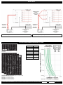
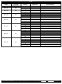
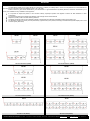
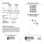
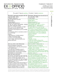
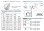
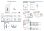
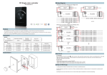
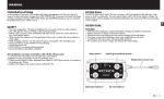
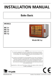
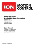
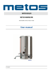
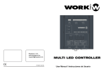
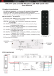
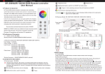
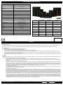
USER’S MANUAL PANELS NL101-00X
PANELS SWITCH FUSE :
Function of the device
Manufacturing
Number of circuits
Number of poles
NL101-00X
12 or 24Vdc electric switchoard
ATO fuses protected
certified ISO 9001 - NAVYLEC® a brand of
ANNECY ELECTRONIQUE – FRANCE
from 1 to 8
single pole
Fuses rating
standard mounted 5 / 10A replaceable, maximum 10A
Fuses types
plug-in types ATO Littlefuse
Power supply
Green LED
12 or 24Vdc
power on
Electric connection input
faston 6.3mm terminals positives according the panel
and one negative
Electric connexion output
faston 6.3mm terminals according the panel
PANELS
Fixing
Front panel material
Color
Protection
4 provided screws stainless black
40 x 140
10A
115x25x38
black epoxy painting, white and yellow serigraphy
NL101-002
60 x 140
5A + 10A
92x45x38
circuit varnish protected
NL101-003
80 x 140
2x5A + 10A
92x65x38
NL101-004
100 x 140
3x5A + 10A
92x85x38
NL101-005
120 x 140
3x5A + 2x10A
92x105x38
NL101-006
140 x 140
3x5A + 3x10A
92x125x38
NL101-007
160 x 140
3x5A + 4x10A
92x145x38
NL101-008
180 x 140
4x5A + 4x10A
92x165x38
Storage T°
-30° to +85°C
Warranty
CUT OUT
SIZE
LxHxD mm
NL101-001
-20° to +70°C
European directives
STANDARD
FUSE
RATING
aluminium thickness 1.5mm
Operating T°
Homologations
FRONT PANEL
SIZE
HxL mm
Printed circuit NF C 93-173
2004/104/CE, 2002/96/CE (2003), 2002/95/CE (2003) RoHS
2 years
ENGLISH
Use and description
The range of on-board electric panels NL101 with plug-in fuses allows ensuring an easy distribution, sure and flexible according to the number of output to be protected for the
main service circuit 12 or 24Vdc. The use of plug-in fuses is spread and makes it possible to easily change the rating protection without disassembling, by the front face.
Security measures
a.
Installation instructions must be followed carefully to place the NL101.
b.
The NL101 must be used in accordance with its specifications.
c.
Any intervention on the on-board electric circuit must be done according to the current legislation.
d.
The electric wire cross-section must adapt themselves to the amperage of the circuit and their length must be as short as possible. All connections must be done correctly.
e.
It is not possible in the range of this manual to train the installer with all the knowledge on the electric systems which can be necessary to install this product correctly. In
case of doubt we recommend you to call a professional.
f.
The panels should not be installed in an explosive environment such as an engine room or as a battery compartment because the switches employed are not explosionproof.
Installation
The panel NL101 can be used only on one electric circuit of 12 or 24Vdc. Check attached diagram for correct connection. This diagram shows standard installation of the panel; it
cannot be used as detailed wiring guide for a specific electric installation.
Concerning cutting to be realized and the screw installation (4 screws provided stainless black treatment) please consult the panel diagram on scale 1 joined.
The main positive connection must be disconnected from the terminal of the battery having to feed the panel to avoid any risk of short-circuit lasting the installation of
this panel.
Connection of the positive outputs, 1 to 8 according to the panel:
Check the fuses rates and their adequacy with the consumers connected on each circuit. If necessary, withdraw and replace the fuse whose value is not adapted.
Each circuit can provide up to 10A maximum. To determine the good positive wire cross-section (red color preferably) according to the amps of the consumer, use the
“Wire Length” table of this manual to help you. Use then Faston females terminals isolated from 6,3mm (color according to the wire cross-section: Red/1,5mm ²;
Blue/2,5mm ²; Yellow/6mm ²), crimp them on wire and plug in the termination of these wires on the respective strips 6,3mm of the outputs. At this level we advise you
to locate these wires by sticking labels according their output number 1 to 8 and also for several panels T1, T2, T3, etc
Consumers negative connection:
These tables do not ensure the distribution of the negative. Use the same wire cross-sections that for the positive and connect them on a common mass bar existing or
to install in general near the boat’s electric switchboard.
Panel power supply connection:
Each panel has a negative input (printed mark “- IN”) to allow the green LEDs of state lighting. Use a 1mm ² cross wire (black color preferably), crimp a 6,3 mm female
Faston isolated (as above) then plug in the termination of this wire on the strip “- IN”. The other end of negative wire must be connected to the common mass bar. In
the event of use of several panels, it is possible to inter-connect them “- IN” and to connect only one negative on the common bar of negative. For the positive
connection (panels NL101-004 to NL101-008 have several input “+ IN” in parallel which can thus be added to use more current, See Fig. B) it is necessary to make the
amps addition of the consumers being able to be used in the same time. This calculation appears more realistic than to make the addition of all the fuses amps at the
output protection and will make it possible to have a wire cross-section /optimal current. According to the amp to be brought to the electric control panel you will
determine a wire cross-section of power supply adapted between the battery (positive terminal) and this panel using the “Wire Length” table of this manual. The same
wire cross-section between the negative terminal of the battery and the common mass/distribution bar need to be used. The Faston 6,3mm terminals can receive at
maximum isolated yellow female Faston 6,3mm for 6mm ² wire cross-section. That explains the presence of 2, 3 or 4 input positives on the back-side panel if the amps
to be brought by the panel cannot be supported by only one wire of 6mm ². In this case a battery wire of the maximum cross-section need to be connected in a positive
bar distribution near the panel, it is easy then to send towards the panels several positive wires of 6mm ².
NAVYLEC ANNECY ELECTRONIQUE – Parc Altaïs – 1 Rue Callisto - F74650 CHAVANOD – France Tel : +33/0 450 02 90 90 Email : [email protected] Web : www.navylec.com Doc : 00253207-v1
ENGLISH
Installation (rest)
It is strongly misadvised using these Faston plug as derivation with the risk to cause an overload on the electric wire. In the event of use of several panels it is necessary
to take their power supply directly on the positive and negative external bars.
Wire choice, example: a 8 circuits panel NL101-008 which must provide 50 Amp - distance battery/table: 5 meters => choose according to the Wire Length table (2x5
meters = 10m), a positive wire of 25mm2 (idem for the negative one) to the common positive bar near the NL101-008, use 4 wires of 6mm ² to the panel and a gross
cross-section of 24mm ² will be obtained.
Any departure from the battery (at source) must be protected by a main fuse (on the positive one, according to the amps/consumption charges) and to have a system
switch (ISO10133). For the panels electric wire protection, battery side, the selected fuse will be given by the addition of all the values present on the panels.
Stickers
Each panel is delivered with a 36 labels standard sheet (text FR, EN and pictos). Optional sheets of 132 labels are proposed. They make it possible to customize your
NAVYLEC electric switchboard. The labels need to be stick in the white rectangles. The labels material is made of vinyl high performance which guarantees strength to
moisture and a long lifespan.
Use
When the panel power supply is connected:
Check that the switches are in position 0 (Stop)
Switch On the main battery switch
Push all the switches in positon 1 (On), check that the green LED of each circuit indicates the power on and the correct operation of the connected consumers.
The fuses ensure, according to their rates, the protection of the connected devices. In overconsumption or short-circuit case, they are cut. Some new fuses to have if
replacement needs to be made is advised for the user.
Note: In the event of overload and fuse fusion the green LED dies out because the circuit is not any more under voltage. The replacement of the fuses is done by
extraction on the front panel. Their calibration is determined by the nature of connected electric consumers (refer to the technical documentation of your equipments or
the technical labels stuck on those), respect a maximum rate of 10A per circuit.
Warranty conditions
It has a 2-year warranty. The purchase invoice attests authenticity.
NAVYLEC ANNECY ELECTRONIQUE, ISO9001 certified company, devotes special attention to manufacturing quality and certifies that the panels NL101 have been
manufactured in accordance with the current standards and legal provisions. All electric switchboards have been checked and tested during manufacturing. Not following
the instructions and provisions in this manual might damage the unit, which might not work according to its specifications. This could lead to warranty cancelation.
Responsibility clause
NAVYLEC ANNECY ELECTRONIQUE declines responsibility due to misuse of the NL101 even if there are errors in this manual or in the case of use that is inconsistent
with the purpose of the product.
WIRE LENGHT / CROSS-SECTION - CURRENT
Maximum length of wire usable according to the section according to the intensity having to cross it (Meters)
mm²
CURRENT (Amperes)
1A
2A
3A
4A
5A
6A
7A
8A
10A 15A 20A 25A
0,5
10
5
3,3
2,5
2,2
2
1 19,6
10
6,6
4,9
3,9
3,3
2,8
2,4
1,5
29 14,7
10
7,4
5,9
4,9
4,2
3,7
2,9
2 39,3 19,6 13,1
10
7,9
6,6
5,6
4,9
3,9
2,5 49,1 24,6 16,4 12,3
10
8,2
7
6,1
4,9
3,3
3 58,9 29,5 19,6 14,7 11,8
10
8,4
7,4
5,9
3,9
4 78,6 39,3 26,2 19,6 15,7 13,1
10
9,8
7,9
5,2
3,9
5 98,3 49,1 32,7 24,5 19,6 16,4
14
10
9,8
6,5
4,9
6
58,9 39,3 29,5 23,6 19,6 16,8 14,7
10
7,9
5,9
4,7
7
68,8 45,8 34,4 27,5 22,9 19,6 17,2 13,8
10
6,9
5,5
10
98,3 65,5 49,1 39,3 32,7
28 24,6 19,6 13,1
10
7,9
15
98,3 73,7 58,9 49,1
42 36,8 29,5 19,6 14,7 11,7
20
98,3 78,6 65,5 56,1 49,1 39,3 26,2 19,6 15,7
25
98,3 81,9 70,2 61,4 49,1 32,7 24,6 19,6
30
98,3 84,2 73,7 58,9 39,3 29,5 23,6
35
98,3 85,9 68,8 45,8 34,4 27,5
40
98,3 78,6 52,8 39,3 31,4
50
98,3 65,5 49,1 39,3
60
78,6 58,9 47,2
70
68,8
55
95
74,7
120
Values at 40°c of temperature, under 12V, for a maximum of 3% voltage drop, flex-wire
coppers multistranded - These values are more restrictive than those defined in appendix A
according to ISO10133 Electric Systems - Small Craft
30A
35A
40A
50A
60A
70A
80A
90A
100A
6,6
9,8
13,1
16,4
19,6
22,9
26,2
32,7
39,3
45,9
62,2
78,6
5,6
8,4
11,2
14
16,8
19,6
22,4
28
33,7
39,3
53,3
67,4
4,1
7,4
9,8
12,3
14,7
17,2
19,4
24,6
29,5
34,4
46,7
58,9
6
7,9
9,8
11,8
13,7
15,7
19,6
23,6
27,5
37,3
47,1
8,2
9,8
11,4
13,1
16,4
19,6
22,9
31,1
39,3
7
8,4
9,8
11,2
14
16,8
19,6
26,7
33,7
8,6
9,8
12
14,7
17,2
23,3
29,5
10,9
13,1
15,3
20,7
26,2
9,8
11,8
13,7
18,7
23,6
Meters maxi.
Notes :
The overall length of wire includes the total length positive and negative
For a use in 24V => multiplier par 2 la longueur donnée dans le tableau
For 40°c of temperature values and 6% of voltage drop => multiply by 2 the length given in the table
For 40°c of temperature values and 9% of voltage drop => multiply by 3 the length given in the table
For 40°c of temperature values and 12% of voltage drop => multiply by 4 the length given in the table
NAVYLEC ANNECY ELECTRONIQUE – Parc Altaïs – 1 Rue Callisto - F74650 CHAVANOD – France Tel : +33/0 450 02 90 90 Email : [email protected] Web : www.navylec.com Doc : 00253207-v1
INSTALLATION
Fig. A : Standard installation or low current
Fig. B : Optimum power distribution installation
OPTIONS & TIME-CURRENT CURVE FOR ATO FUSES
Ampere Rating (A)
Colour Code
1
black-noir
2
grey-gris
3
violet
4
pink-rose
5
orange
7,5
brown-marron
10
red-rouge
Calibre Ampère (A)
Code Couleur
STANDARD STICKERS SUPPLIED
NL110-201
OPTIONAL LABELS SHEET FOR NL101
MATTER: STICKER VINYL LONG LIFESPAN, PRECUT, SIZE 22,6 X 9MM
NL110-101 132 STIKERS PICTOS
NL110-001 132 STIKERS FR FRENCH
NL110-002 132 STIKERS EN ENGLISH
NL110-003 132 STIKERS ES SPANISH
NAVYLEC ANNECY ELECTRONIQUE – Parc Altaïs – 1 Rue Callisto - F74650 CHAVANOD – France Tel : +33/0 450 02 90 90 Email : [email protected] Web : www.navylec.com Doc : 00253207-v1
NL101
NAVYLEC ANNECY ELECTRONIQUE – Parc Altaïs – 1 Rue Callisto - F74650 CHAVANOD – France Tel : +33/0 450 02 90 90 Email : [email protected] Web : www.navylec.com Doc : 00253207-v1
NL101
NL101-001
Input total
Current +IN
Permissible max.
10A
NL101-002
20A
NL101-003
30A
NL101-004
40A
NL101-005
50A
NL101-006
60A
NL101-007
70A
NL101-008
80A
Article
Number
Output +OUT
Standard
Output +OUT
Replacement
Your functionalities
10A
10A
5A
5A
5A
10A
5A
5A
5A
10A
10A
10A
5A
5A
5A
10A
10A
10A
5A
5A
5A
10A
10A
10A
5A
5A
5A
10A
10A
10A
5A
5A
5A
5A
10A
10A
NAVYLEC ANNECY ELECTRONIQUE – Parc Altaïs – 1 Rue Callisto - F74650 CHAVANOD – France Tel : +33/0 450 02 90 90 Email : [email protected] Web : www.navylec.com Doc : 00253207-v1
BATTERIES
The table below enables you to quickly identify the composition of a battery or a battery bank in 12V or 24V composed of one or more batteries for
the most current configurations (also other batteries types in 4V or 8V exist).
Indeed to ensure a good electric distribution by the switchboard or a good measurement by Battery Monitors, NAVYLEC recommends you to
check your installation for any installation of its equipment:
It is important to respect the position of the connector industry input/output positive and negative to ensure the best distribution of loadconsumption
The component cables of the bridges inter batteries must be length and of section identical
Replace any battery cable or terminal seeming defective
The battery enclosure must be most moderate possible in temperature and sufficiently ventilated according to the battery type
Any departure of battery (at source) must be protected by a general fuse (in the positive, according to the load intensity/consumption) and to have
a switch system (ISO10133)
BATTERY 12V
BATTERY 24V
12V with 12V batteries (100AH)
24V with 12V batteries (100AH)
12V with 6V batteries (200AH)
24V with 6V batteries (200AH)
12V with 2V cells (600AH)
24V with 2V cells (600AH)
NAVYLEC ANNECY ELECTRONIQUE – Parc Altaïs – 1 Rue Callisto - F74650 CHAVANOD – France Tel : +33/0 450 02 90 90 Email : [email protected] Web : www.navylec.com Doc : 00253207-v1