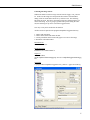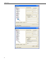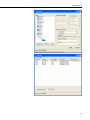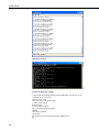
1
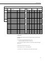
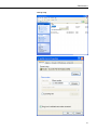
INSTRUCTION MANUAL
RWIS Stations
3/05
C o p y r i g h t ( c ) 2 0 0 5
C a m p b e l l S c i e n t i f i c , I n c .
Warranty and Assistance
The RWIS STATIONS are warranted by CAMPBELL SCIENTIFIC, INC. to
be free from defects in materials and workmanship under normal use and
service for twelve (12) months from date of shipment unless specified
otherwise. Batteries have no warranty. CAMPBELL SCIENTIFIC, INC.'s
obligation under this warranty is limited to repairing or replacing (at
CAMPBELL SCIENTIFIC, INC.'s option) defective products. The customer
shall assume all costs of removing, reinstalling, and shipping defective products
to CAMPBELL SCIENTIFIC, INC. CAMPBELL SCIENTIFIC, INC. will
return such products by surface carrier prepaid. This warranty shall not apply
to any CAMPBELL SCIENTIFIC, INC. products which have been subjected to
modification, misuse, neglect, accidents of nature, or shipping damage. This
warranty is in lieu of all other warranties, expressed or implied, including
warranties of merchantability or fitness for a particular purpose. CAMPBELL
SCIENTIFIC, INC. is not liable for special, indirect, incidental, or
consequential damages.
Products may not be returned without prior authorization. The following
contact information is for US and International customers residing in countries
served by Campbell Scientific, Inc. directly. Affiliate companies handle repairs
for customers within their territories. Please visit www.campbellsci.com to
determine which Campbell Scientific company serves your country. To obtain
a Returned Materials Authorization (RMA), contact CAMPBELL
SCIENTIFIC, INC., phone (435) 753-2342. After an applications engineer
determines the nature of the problem, an RMA number will be issued. Please
write this number clearly on the outside of the shipping container.
CAMPBELL SCIENTIFIC's shipping address is:
CAMPBELL SCIENTIFIC, INC.
RMA#_____
815 West 1800 North
Logan, Utah 84321-1784
CAMPBELL SCIENTIFIC, INC. does not accept collect calls.
CS500 Table of Contents
PDF viewers note: These page numbers refer to the printed version of this document. Use
the Adobe Acrobat® bookmarks tab for links to specific sections.
1. General ........................................................................1
2. Specifications .............................................................1
2.1 Temperature Sensor ..................................................................................1
2.2 Relative Humidity Sensor .........................................................................2
3. Installation...................................................................2
4. Wiring ..........................................................................6
5. Example Programs .....................................................6
5.1 Example for CR1000 ................................................................................7
5.2 Example for CR10X .................................................................................7
6. Long Lead Lengths.....................................................8
7. Absolute Humidity ......................................................9
8. Maintenance ..............................................................11
9. References ................................................................11
Figures
1.
2.
3.
4.
5.
CS500 and 41301 Radiation Shield on a CM6/CM10 Tripod Mast ...........3
CS500 and 41303 Radiation Shield ............................................................4
CS500 and 41003 Radiation Shield on a CM6/CM10 Tripod Mast ...........4
Radiation Shield, CS500, and 41381 Adapter ............................................5
CS500 Wiring .............................................................................................5
1.
2.
3.
4.
5.
Datalogger Connections..............................................................................6
Calibration for Temperature .......................................................................6
Calibration for Relative Humidity...............................................................6
Wiring for CR1000 and CR10X Examples.................................................7
CR10(X) Wiring for Example 1..................................................................9
Tables
i
This is a blank page.
RWIS Stations
Campbell Scientific RWIS stations are intended to automatically collect
weather and road information. Standard met sensors are used with surfacespecific sensors to measure additional site conditions. As with all Campbell
Scientific stations, these are configurable by the customer to their
requirements.
RWIS stations conform to national standards defined by the National
Transportation Communications for ITS Protocol (NTCIP). They have
developed standards for implementation of several aspects of RWIS. The
NTCIP guide is available at http://www.ntcip.com/library/guide.asp. The
specification that we conform to is ESS-1204. ESS (Environmental Sensor
Station) is a term that refers to the weather station.
Each station that we supply has the following components listed below.
Power enclosure for the batteries:
AC recharge
DC recharge/tripod for solar panels
Equipment enclosure:
CR10X-2M or CR1000
SDM-SIO4
NL110
Modem
In addition to the standard met sensors, there are options that add function to
the station to allow it to make road-related measurements. Some are listed
below. As with any station, if a customer needs another measurement that they
feel is appropriate, it will be added if possible.
SR50 (acoustic snow sensor)
Lufft IRS21 (road sensor – 2 ea generally)
Present weather (such as Vaisala PWD22)
Camera
107 probes for sub surface temperatures
The purpose for the instruments in the equipment enclosure doesn't need a lot
of explanation with the exception of the SDM-SIO4 and the modem.
The SDM-SIO4 is used primarily for interfacing to the IRS21. The handshake
required to communicate with the sensor doesn’t allow for operation with the
CR10X alone since four control ports are required. In addition, many of the
sensors used with this application have serial interfaces making the SDM-SIO4
a good addition to the application.
The modem used needs an RS-232 interface and also needs to be faster than the
9600 baud offered in Campbell modems. This is due to the requirement for
image retrieval from a camera. If using FTP (desired) to extract an image from
the logger, FTP shuts down before the image can be retrieved.
1
RWIS Stations
Theory of operation
The NL110 provides communication for all system devices, converts logger
measurements to NTCIP compliant data, routes images from an installed
camera to the logger, provides SNMP communication, and stores text
generated in the CR10X to text values required by NTCIP.
Customers call in through the modem and establish a PPP connection. This
connection makes a private network and has its own IP address.
The NL110 also provides the necessary function for providing NTCIP
compliant data to ANY NTCIP compliant software that can interrogate NTCIP
compliant systems. This makes the RWIS system compatible with other
systems supplied by other manufacturers.
The logger makes all measurements. As they are made, output is generated
that the NL110 accepts. The NL100 then converts the data to NTCIP
compliant values by changing the variable names to variable names that
comply with the specification.
The camera installed outputs an image automatically on a fixed interval. As
the image is sent, it is routed from the camera to the 10 base t input on the
NL110. The NL110 then routes the image to the logger for later use. One
image is stored in the logger, and when a new image is sent, it replaces the
image last sent.
All sensors have their own measurement instructions, but there are some
unique setups for the equipment installed in the ESS. The following pages
describe those setups.
2
RWIS Stations
Loggermap
diff
channel
1
2
3
4
5
6
se
channel
1H
2L
3H
4L
5H
6L
7H
8L
9H
10L
11H
12L
p1
p2
e1
e2
e3
c1
c2
c3
c4
c5
c6
c7
c8
sensor/color
function
humidity
Air temp
open option(oo)
wind direction
solrad
solrad
sub surface
sub surface
sub surface
sub surface
rain y/n(oo)*
rainy/n(oo)*
wind speed
tipping bucket
12v/color
AG/color
G/color
sub surface
wind direction
sdm-sio4
sdm-sio4
sdm-sio4
snow depth
Logger Setup
The CR10X-2M *D and *A menus set the logger for image collection and pb
operation.
*D15 location 1 is the pakbus address and is set to 1
fill in the remainder of the table with values of 4
*D16 location is the amount of memory to set aside for the image in the logger
and is set to 6
*D18 location is the beacon and is set to 60
*D19 location 01 is set to 17 with nothing after
*A location 6 is set to 3000 for the text values that ess1204 requires
3
RWIS Stations
NL110 Setup
NL100/105:
TLink config: [RS232]
RS485 config: [disabled]
CS I/O config: [PakBus]
CS I/O SdcAddr/bps: [SDC7]
CS I/O beacon interval (sec): [60]
RS232 config: [PPP]
RS232 bps: [38k]
EtherNet 10BASE-T: [enabled]
10BASE-T port IP address: [192.168.7.53]
10BASE-T port network mask: [255.255.255.0]
Is there a default gatway: [no]
PakBus node Id: [678]
Clock neighbor node Id: [1]
PakTcp server config: [enabled]
PakTcp server port number: [4001]
PakTcp client config: [disabled]
Configuration monitor telnet port: [23]
Telnet session password: [nl100]
Serial server watchdog (minutes): [2]
Power Saving Mode: [disabled]
MODBUS/TCP gateway config: [disabled]
SNMP Version 2: [enabled]
Logger ID for PakBus: [1]
PMPP PC Address: [50]
Network Address for PPP: [192.168.18.150]
Network Mask for PPP: [255.255.248.0]
PPP Password (Max. 8 characters): [ntcip]
Enable Ethernet Port: [enabled]
Set Modem Answer Rings (1: default): [1]
Modem Initialization: [AT]
NL100/105 (ver, last, curr, show, edit, defaults, reset, help, bye):
4
RWIS Stations
Dial up Setup
5
RWIS Stations
6
RWIS Stations
Collecting the image as data
When FTP cannot be used for image removal from the logger, cora_cmd can
be. In this case the image is treated just like data in that it is downloaded
during a task for routine data removal or by itself in a task. The following
batch files are used. The files in the images below have different names, but
do the same thing. If you’re going to get data and a picture during the same
call, the following set up can be used in the Loggernet tasks.
User may or may not be needed for the function.
All files need to be placed in the programs\campbellsci\loggernet directory
1. connect with rasconnect
2. connect to the station and collect the data
3. execute pictask.bat which in turn calls getpic.txt to retrieve the image
4. disconnect with rasdisconnect
Rasconnect.bat
RASDIAL rwis1 user
Rasdisconnect.bat
RASDIAL rwis1 /DISCONNECT
Getpic.txt
connect localhost;
get-file rwispbadr1 CRD:netcam.jpg.tmp --save-as=c:\campbellsci\loggernet3\netcam.jpg;
exit;
pictask.bat
c:\"program files\campbellsci\loggernet3\cora_cmd.exe" <getpic.txt>what.log
7
RWIS Stations
8
RWIS Stations
9
RWIS Stations
FTP image retrieval
To FTP an image from a logger
C:\Documents and Settings\donbrown.CSI-INTRANET>ftp 192.168.18.150
Connected to 192.168.18.150.
220 FTP server ready.
User (192.168.18.150:(none)): ntcip
331 Password required.
Password:ntcip
231 User name accepted.
ftp> get netcam.jpg.tmp netcam.jpg
200 OK.
150 ready to send file.
226 closing.
ftp: 10796 bytes received in 9.92Seconds 1.09Kbytes/sec.
ftp>
10
RWIS Stations
The image is sent to the default directory.
Ayantra Modem Setup
Ayantra IML560
Switch
1
2
3
4
5
6
7
8
9
10
11
12
Position
off
on
off
on
off
off
off
on
on
off
off
off
The modem is set to 38.4kb to match the speed of the serial port on the NL110.
CAUTION
Be aware that the power connector of the Ayantra modem
is the same as for our loggers, except that the connections
are reversed. Be certain to wire the power of the modem
according to the label on the modem.
11
RWIS Stations
Blackbox Modem Setup
Blackbox MD3200A setup for use with Rwis stations
Follow the manual instructions for configuring the modem
Set the following
AT&F1
ATS0=1
ATS46=136
AT&D0=0
AT&W
Netcam Setup
12
Sets the default values
Answers after 1 ring
Disables compression
Ignores DTR
Writes the changes
RWIS Stations
Troubleshooting
There may be times that a partial image is seen. In this case an image was
being transferred to the logger, and something interrupted it. Calling in during
the image transfer can cause this to happen. Ideally a polled camera would
solve this problem since we could ask for an image with a control port just
before a scheduled call. The problem can be minimized by scheduling image
downloads at times other than scheduled calls. For an hourly schedule, if the
camera is set to 13 minute downloads, interruptions of the image transfer are
very seldom.
13
RWIS Stations
If there is a time that the station is called but the authentication fails, the
NL110 is hung and needs to be reset. This can done locally by using the
NL110 configuration menu, or by programming a control port to power rest the
modem on a regular interval. The control port is wired to the SW12V ctrl, and
the NL110 is powered by the SW12V of the CR10X-2M.
If there is a time that the phone lines are good but the connection rings busy,
the modem could be hung and needs to be reset. This, too, can be managed by
a power reset with the modem also being controlled by the SW12V.
Connection speeds for telephones are also a concern in that speeds less that
about 16kb are not practical for image retrieval. Since the modem connects to
the serial port of the NL110 and the maximum speed of the serial port is
33.6kb, a modem with at least that speed is needed. Experience has shown that
with speeds less than about 16kb, FTP times out and there is no image sent.
Possible configurations
There are two verified ways to connect to the RWIS station.
The first is phone modem to NL110. Using the setups described in earlier
sections reliable communication is accomplished.
The second is phone modem to RF400 to NL110. In this case, a null modem is
needed for connection to the base RF400 and the modem. On the logger side a
straight cable is used to connect the RS-232 port of the RF400 to the RS-232
port on the NL110.
Setups for the RF400s are all default with the following exceptions.
Active interface – rs232
Baud rate 38.4 kb
RF_ON 24ma
Programming
There are some requirements of ESS-1204 that require special consideration
for the CR10X-2M. They are text and large numbers. Large numbers are
14
RWIS Stations
converted to text with the P190 instruction, and text is created also with the
P190. This is the set settings instruction, and when using this technique the 68
instruction is used to spell out the text. In both cases the form is
variablename=value. There is a limit though to the amount of text that can be
created. Twenty-nine characters maximum are allowed on either side of the
equal sign for CR10X-2M datalogger.
ESS-1204 defines all the measurements to be made. All measurements aren't
required, but values have to be provided for all measurements. If a sensor isn’t
part of a station, the specification requires that a no sensor value be present.
The way that this is done is by writing an initialization subroutine to provide
values for all sensors and creating values that correspond to the type of
measurement. The subroutine is executed one time at startup or when the
program is recompiled. In this way default values are already established. As
sensors are added in the measurement section of the of the program, the
measured values replace the default values in the output.
15
RWIS Stations
This is a blank page.
16
This is a blank page.
Campbell Scientific Companies
Campbell Scientific, Inc. (CSI)
815 West 1800 North
Logan, Utah 84321
UNITED STATES
www.campbellsci.com
[email protected]
Campbell Scientific Africa Pty. Ltd. (CSAf)
PO Box 2450
Somerset West 7129
SOUTH AFRICA
www.csafrica.co.za
[email protected]
Campbell Scientific Australia Pty. Ltd. (CSA)
PO Box 444
Thuringowa Central
QLD 4812 AUSTRALIA
www.campbellsci.com.au
[email protected]
Campbell Scientific do Brazil Ltda. (CSB)
Rua Luisa Crapsi Orsi, 15 Butantã
CEP: 005543-000 São Paulo SP BRAZIL
www.campbellsci.com.br
[email protected]
Campbell Scientific Canada Corp. (CSC)
11564 - 149th Street NW
Edmonton, Alberta T5M 1W7
CANADA
www.campbellsci.ca
[email protected]
Campbell Scientific Ltd. (CSL)
Campbell Park
80 Hathern Road
Shepshed, Loughborough LE12 9GX
UNITED KINGDOM
www.campbellsci.co.uk
[email protected]
Campbell Scientific Ltd. (France)
Miniparc du Verger - Bat. H
1, rue de Terre Neuve - Les Ulis
91967 COURTABOEUF CEDEX
FRANCE
www.campbellsci.fr
[email protected]
Campbell Scientific Spain, S. L.
Psg. Font 14, local 8
08013 Barcelona
SPAIN
www.campbellsci.es
[email protected]
Please visit www.campbellsci.com to obtain contact information for your local US or International representative.