1
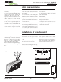
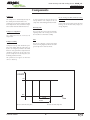
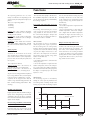
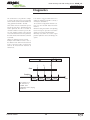
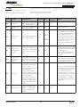
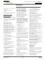
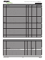
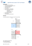
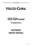
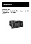
HEAT RECOVERY UNITS WITH COOLING CIRCUIT
CONTROLS MANUAL
URHE_CF
EN
0512. 6180758_01
English
Index
Introduction
4
Main characteristics
5
Installation of remote panel
5
Wiring of remote panel
6
User interface
6
Menù levels
8
Components
9
Functions
10
Diagnostics
12
Parameters setting
15
Parameters
16
Technical characteristics
23
Use of the control device
24
Responsabilities and residual risk
24
Heat recovery unit with cooling circuit - URHE_CF 0612-6180758-rev. 01
Introduction
The control installed on the URHE_CF units is
a compact device usually provided to control
air conditioning units.
Carefully and thoroughly read all the
information referred to in this manual. Pay
particular attention to the norms accompanied
by the indication “DANGER” or “ATTENTION”
since, if not observed, may cause damage to
the unit or to people.
• If any malfunctions are found out, which are
not included in this manual, please contact
the local After-Sales Service immediately.
•
AERMEC S.p.A. declines all liability for any
damage caused by the improper use of the
machine or the partial or superficial reading of
the information contained in this manual.
• Installation and maintenance must
be performed by qualified and
experienced personnel, having the
requirements that are foreseen by
law 46/90 and/or the DL 380/2001
for the electrical/electronic and
air-conditioning installation, with
consequent registration at the local
CHAMBER OF COMMERCE, if this is
not so, AERMEC S.p.A. declines all
responsibility regarding the safety of
the product.
THE MANUFACTURER DECLINES ALL
LIABILITY FOR DAMAGE TO THINGS OR
INJURY TO PERSONS AND ANIMALS
CAUSED BY THE FAILURE TO OBSERVE
THE INSTRUCTIONS AND STANDARDS IN
THIS MANUAL.
Although suitable risk analysis have
been performed during the design of the
URHE_CF unit, PAY ATTENTION to the
pictograms on the machine which help
understand the manual better, rapidly
catching the attention of the reader
concerning the risks which can not be
avoided or sufficiently limited through
the use of technical protection means and
measures.
GENERAL
HAZARD
SIGNAL
Carefully adhere to all the indications
Controls manual
next
to
the
icon.
Failure to comply with the
instructions may generate hazardous
situations with possible damage to the
health of the operator and user in general.
DANGEROUS ELECTRICAL VOLTAGE
SIGNAL
Carefully adhere to all the indications
next to the icon.
The signal indicates components of
the unit or, in this manual, specifies actions that
could generate electrically-related risks.
for the improvement of its product
and is not obliged to add these
modification to machines of previous
manufacture, which have already
been delivered or are being built.
The warranty conditions are any subject
to the general sales conditions at
the moment the contract is finalised.
GENERAL PROHIBITION SIGNAL
Carefully adhere to all the indications next to the
icon that limit actions in order to guarantee better
operator safety.
MAIN WARRANTY
CONDITIONS
• The warranty does not cover payment for
damages cause by the incorrect installation of
the unit by the installer.
• The warranty does not cover payment for
damages cause by the improper use of the
unit by the user.
• The manufacturer is not responsible for
accidents to the installer or user that are due
to the improper use and incorrect installation
of the unit.
The warranty is not valid when:
• the maintenance and repairs have been
performed by unauthorised persons or
companies;
• the unit has been previously repaired or
modified with spare parts that are not original;
• the unit has not undergone suitable
maintenance;
• the instructions described in the present
manual have not been followed correctly;
• unauthorised modifications have been made.
Note:
The Manufacturer reserves the right at
all times to make any modification
4
GB
Heat recovery unit with cooling circuit - URHE_CF 0612-6180758-rev. 01
Main characteristics
Generalities
The URHE_CF units are provided with
an electrical panel including the power
supply section and the controls (the
3-ways valve for the hot water coil, if
required, and the actuators are included) to manage all the functions of the
cooling circuit. The controls include:
NTC temperature probe on the exhaust
air flow, NTC temperature probe for
the fresh air flow, differential pressure
switch for the fresh air filter. When the
free-cooling accessory is required, the
dampers and the actuators are provided
for. A remote control panel is also inclu-
ded for the remote management of the
unit (max. distance 150m, wiring cable
not included).
The main functions of the control panel
are:
• room temperature control, based on the
temperature of the exhaust air;
• management of the de-frosting processes;
• remote ON-OFF;
• Summer/Winter switch;
• electric heating coil control (if required);
• water heating coil control (if required);
• User interface with two different levels
of accessibility with password (inside the
electrical panel);
• remote panel (max. distance 150m) to
be connected directly to the unit (wiring
cable not included).
Troubleshooting
The controls check and mark the following possible failures:
• temperature probe failure
• cooling circuit high and low pressures
• compressor thermal protection
• fan thermal protection.
Installation of remote panel
The connecting terminal of the remote
control and the connecting terminal on
the electrical panel has to be connected
by means of shielded electrical cables
with min. 0.5 mm2 section and max.
150m lenght (cables non included).
Please, refer to the paragraph “Wiring of
remote panel” for the connecting procedure.
To access the keyboard on the remote
panel remove the front panel (with a
screwdriver or similar tool) as shown in
fig. 01.
The cables must pass through the central
hole in the rear section (fig. 01).
drill four 4 mm diameter holes in the wall
at the specified distance. Fix the black
rear part to the wall with four screws.
After carrying out the necessary connections, close the front section of the keyboard by simply pushing it in place.
The keyboard is designed to be wallmounted. After removing the front part,
central hole for cables
12.10
fig. 02
12.10
55.80
fig. 01
99.50
12.10
80.00
12.10
<IMG INFO>
124.00
Controls manual
5
25.00
GB
Heat recovery unit with cooling circuit - URHE_CF 0612-6180758-rev. 01
Wiring of remote panel
During the connection procedure
between the electrical panel and the
remote control respect the following
rules:
- do not apply to the analogue and digital ouputs powers higher than the ones
declared in this manual;
- make the connections respecting the
wiring diagrams in this manual;
- keep the power supply cables diveded
from the control cables to prevent from
interferences.
n° 3 shielded cables not included
(max. length 150 m; min. section
0.5 mm2)
26
MORSETTIERA
QUADRO ELETTRICO
ELECTRIC TERMINAL
BOARD
24: blue
25: red
26: black
Digital inputs
There are 5 voltage-free digital inputs
identified from here on as ID1….ID15.
AI1, AI2 and AI4 may also be added
to these if they are configured as digital inputs (with parameters Pa H05, Pa
H06, Pa H08).
8 digital inputs are therefore available.
12~ ALL GND GND IA4 IA3 IA2 IA1
SERIAL
TC ID5 ID4 ID3 ID2 ID1
RELAYS 2(2)A 250V~
N
N
8
7
NO1 NO2 NO5 N
6
5
4
3
KEYB
NO3 NO4
2
1
EXP
12~ 12
9
Wiring of remote panel
Important! Never connect the keyboard
when the instrument is on. Avoid shortcircuiting on the cables when the instrument is on: this may damage the instrument.
25
24 25 26
24
Analogue inputs
There are 4 analogue inputs:
• 3 NTC temperature probes
• 1 input which may be configured for
an NTC probe or 4...20mA signal.
The inputs are idetified from here on as
AI1…AI4.
TERMINALE REMOTO
REMOTE TERMINAL
IMG INFO
Layout view rear of the control panel on board on the unit
User interface
User interface
The user interface allows for the control
of all the unit operations:
• operating setting mode
• components checks and controls
• alarms management
Controls manual
Displays
The device shows all the informations
and the alarms by means of a display
and led signals present on the front
panel.
6
GB
Heat recovery unit with cooling circuit - URHE_CF 0612-6180758-rev. 01
Display
Buttons
Heating LED
MODE
Selects the operating mode:
If the Heating mode is enabled, each time
the button is pressed the following sequence
occurs:
stand-by -> cooling -> heating -> stand-by
If the Heating mode is not enabled:
stand-by -> cooling -> stand-by
SET
Resets alarms and modifies the set point.
Press once to reset all inactive alarms that
can be reset manually.
If you hold the button down for 2 seconds,
the unit displays the set point of the set
mode.
MODE
SET
If you press both buttons at the same time
and then release them within 2 seconds, you
go down one level in the display menu.
If you press both buttons for more than 2
seconds, you move one level up.
If the last level of a menu is displayed, press
the button and release it within two seconds
to go up one level.
In menù operating mode it shows the previous label or increases the shown value
(depending on the context).
In Normal mode, the unit displays:
• the control temperature, in tenths of
degrees Celsius with a decimal point or
in Fahrenheit with no decimal point.
• the alarm code, if at least one is active. If several alarms are active, the unit
displays the first alarm listed in the
Alarm Table.
• If temperature control is not based
on the analogue inputs and is linked to
the status of a digital input (AI1 or AI2
configured as digital inputs), the “On”
or “Off” label will be displayed, depending on whether temperature control is
active or not.
• In Menu mode, displaying varies
according it the position. Special labels
and codes are used to help users identify the function that has been set.
Decimal point: when displaying the operating hours, it indicates that the value
must be multiplied x 100.
In normal operation, the display shows
the temperature given by the NTC probe
on the exhaust flow (room temperature).
To display the setting keep the button
“set” pushed for nearly 3 seconds.
Cooling LED
• ON if the controller
is in Cooling mode
If neither the HEAT LED or the
COOL LED are lit, the controller is in
STANDBY mode.
On board control panel
The control panel on borad of the unit
performs the same functions and displays
the same parameters of the remote
panel.
The setting procedure are the same
described for the remote panel.
The “Upwards arrow” button operates also
as “Mode” button, while the “Downwards
arrow” button operates also as “Set” button.
Leds
LED 1 compressor 1
• ON if compressor 1
is active
• OFF if compressor 1
is inactive
• BLINK if safety timing is in progress
Defrost LED
In menù operating mode it shows the following label or decreases the shown value
(depending on the context)
• ON if the unit is in
Heating mode.
• ON if defrosting is
active
• OFF if defrosting
is disabled or has been
completed
• BLINK if timing is in progress (defrosting time)
Parameter programming – Menu levels
The setting parameters of the control
device may be modified through the
control panel keyborad. The various
parameters are organized in groups
accessible when pressing the “mode”
and “set/alarm” buttons at the same
time. Each menu level is identified by a
mnemonic code which appears on the
display. For more info please refer to the
following page.
Electric heater LED
• ON if the internal
anti-freeze electric heater
are on
• OFF if the internal anti-freeze electric
heater are off
Controls manual
7
GB
Control Probe
Current Alarm
Level 0
Controls manual
Parameter Index H01...
Parameter Index C01...
Parameter Index F01...
Input Code 01...05
Configuration Parameters CnF
Compressor Parameters CP
Fan Parameters FAn
Digital inputs Id
Parameters PAr
8
Number of hours Parameter
Number of hours Parameter
Numero ore parameto
Compressor 1 hours OH1
Compressor 2 hours OH2
Pump hours OPH
Operating Hours OHr
Parameter Index d01...
Defrost Parameters dFr
Password Value
Parameter Index r01...
Antifreeze Parameters Fro
Password Pss
Parameter Value
Parameter Index P01...
Pump Parameters PUP
Parameter Value
Parameter Value
Parameter Value
Parameter Index A01...
Parameter Value
Parameter Value
Parameter Value
Level 4
Levels hierarchy
The level 0 always shows the exhaust air
temperature or an alarm, if active.
Alarm Parameters ALL
Digital Input Status
Current alarms Code E00
Alarms Err
Analogue Input Value
Set Heating Value
Label Set Heating HEA
Input Code t01...t04
Set Cooling Value
Level 3
Label Set Cooling Coo
Level 2
Analogue Inputs TP
Set point SEt
Level 1
Heat recovery unit with cooling circuit - URHE_CF 0612-6180758-rev. 01
Menù levels
To move through the levels and the labels
use the arrow buttons.
GB
Heat recovery unit with cooling circuit - URHE_CF 0612-6180758-rev. 01
Components
Compressor
The compressor is controlled by the relays of
the control panel on board of the unit.
Compressors are turned on and off according
to the temperatures detected and the temperature control functions that have been set.
A safety period must elapse between one
start-up and the next (compressor on...on
safety time) controlled by parameter Pa C02.
Compressor configuration
The reversing valve refers to the “heat pump”
operating mode. The reversing valve is off if
the instrument is OFF and on standby.
The compressor must be connected to
output NO1.
Reversing valve
Electric heating coil (MBX) and Water heating
coil (MBC)
Connect the electric heating coil or the water
heating coil to the NO4 relay output (see
wiring diagrams).
Fans
Compressor timing
Compressor start-up and shut-down operations must comply with the safety times set
by the user using the parameters described
below. A safety period must elapse between
shut-down and start-up of the same compressor (compressor on...off safety time) controlled by parameter Pa C01;
This parameter also applies to when the
device is started up.
The fans are cabled on a single relay output
NO2 (see wiring diagrams). The fans are configured to operate in continous mode.
COMPR
ON
OFF
Pa C01
Time
Pa C02
Pa C01: OFF-ON safety time
Controls manual
Pa C02: ON-ON safety time
9
GB
Heat recovery unit with cooling circuit - URHE_CF 0612-6180758-rev. 01
Functions
The operating parameters are set in the
factory to control the unit depending on the
signals given by the temperature and pressure
probes.
There are 3 operating modes:
• Cooling
• Heating
• Stand-by
Cooling: this is the “summer” operating
mode; in this mode the unit is configured to generate cold air.
Heating: this is the “winter” operating
mode; in this mode the unit is configured to generate hot air.
Stand-by: in this mode the machine
does not perform temperature control
functions and all the alarms remain active.
Setting set points
Activation or de-activation of the loads
varies dynamically according to the temperature control functions set, the temperature/
pressure values measured by the probes and
the set points.
Two set points are defined:
Cooling set point: this is the reference set
point when the unit is in Cooling mode
Heating set point: this is the reference set
point when the device is in Heating mode
Set points can be changed from the keyboard
by accessing submenu “SET” (see menu layout)
or by pressing the set button for 2 seconds.
Set points can be assigned values that fall
within a range determined by parameters Pa
H02 – Pa H01 (Heating) and Pa H04 – H03
(Cooling)
- Pa r14). If the heat pump is off because
the outdoor temperature is too low, the
electric heaters are directly controlled by
the heating set point.
Freecooling and freeheating (accessory
FCExx)
Freecooling and freeheating are used to
cool or heat the internal environment
using outdoor air. The external air enters
the environment through a damper that
mixes it with the recirculated air from inside. Damper control is ON/OFF.
FREECOOLING
The freecooling set point is calculated by
subtracting the value equal to parameter
F26 (freecooling offset in cooling mode)
from the cooling set point. If the freecooling
set point were to coincide with the cooling
set point, the damper would close as the
same time as the compressors are switched
off and any energy saved by using colder
outdoor air would be lost.
This is valid if
• the outdoor temperature is lower than the
cooling set point
• the inside temperature is higher than the
outdoor temperature. If the inside temperature is lower than the outdoor temperature
and both are lower than the cooling set point,
the damper is completely open. The control
hysteresis is 10°C.
were to coincide with the heating set point,
the damper would close as the same time
as the compressors are switched off and any
energy saved by using warmer outdoor air
would be lost.
This is valid if
• the outdoor temperature is higher than the
heating set point
• the inside temperature is lower than the
outdoor temperature. If the inside temperature is higher than the outdoor temperature
and both are higher than the heating set
point, the damper is completely open. The
control hysteresis is 10°C.
Damper closed if temperature is low
Air that is too cold entering the environment
affects the well-being of its occupants. For
this reason, if the outdoor temperature is
lower than Pa F32 (freecooling shutdown
set point), the damper is forced to minimum
opening (Pa F31). If the outdoor temperature
is higher than Pa F32+ Pa F33, the freecooling control returns to normal.
FREEHEATING
The freeheating set point is calculated by
adding the value equal to parameter F28
(freecooling offset in heating mode) to the
heating set point. If the freeheating set point
fig. 01
ON OFF from digital input
Digital inputs ID3, ID4, ID5 and AI4 (analogue
inputs) can be configured to give an ON-OFF
command. If this type of input is activated,
the instrument will turn off all loads and “E00”
appears on the display..
Electric heating coil (MBXxx) or water heating
coil (MBCxx) (accessories) (fig. 1)
ON R
SET POINT HEATING
ON COMP
OFF
Pa C04
In heating mode, the electric heaters or the
coils are activated when AI1 < (SET Heating
Controls manual
Pa C04
R: electric heater
10
GB
Heat recovery unit with cooling circuit - URHE_CF 0612-6180758-rev. 01
Recording operating hours
The device stores the number of operating
hours for the following in the non-volatile
memory:
• evaporator fan
• compressor.
Internal resolution is in minutes.
The values can be displayed by accessing
the menu with the label Ohr (see menu
layout). The whole value is displayed for
values below 999 whereas hours/100 value
along with the decimal point is displayed for
values above 999.For example, 1234 hours
are displayed as follows:
Power failure
If there is a power failure, when the power is
restored the control returns to the state prior
to the power failure. If defrosting is in progress, the procedure is cancelled. All timing
in progress is cancelled and restarted.
Defrost mode stop (fig. 02)
The defrosting process stops if:
• the condensing pressure raises up to the
defrost stop pressure,
• the defrosting process doesn’t stop in 5 min
(max. defrosting time).
12.3
The hours can be reset by pressing the
DOWN button for two seconds (see buttons)
while the operating hours are displayed.
35.48
d02 (defrost start temperature/pressure) or
the compressor is turned off.
• The counter is reset following one of these
events: defrost cycle performed; power failure; change in operating mode.
• The counter is also reset when the temperature/pressure rises above Pa d04 (defrost
end temperature/pressure).
is ON, the control starts the defrost countdown (1 min countdown). When 1 min passed, the control device starts the defrosting
process. At this point Pad06 (compressor..
valve time delay) = 30 sec., the control procedure described in fig. 01 is operated.
This delay prevents the compressor from
liquid returns. During this operation the
safety timings of the compressor are not considered. The defrost starting and stopping
pressures are the following:
• defrost start: 3 bar
• defrost stop: 10 bar.
35
Counter mode
• The defrost time counter is interrupted
when temperature/pressure rises above Pa
In the event of a power failure, the last fraction of hour recorded is set to 0 and the
duration is rounded off by default.
fig. 01
SD
ON
COMPR
Defrosting
The defrost function is only active in Heating
mode.
This function is used to prevent the formation of ice on the surface of the external heat
exchanger.
This significantly reduces the thermodynamic performance of the unit and could cause
it severe damage.
OFF
ON
RV
OFF
Pa d06
Pa d06
COMPR: compressor
RV: reversing valve
SD: start of defrosting
fig. 02
FD
Defrosting is controlled according to pressure.
Defrost start and stop commands are given
on the basis of condensation probe readings
and parameter settings, as described below.
ON
COMPR
OFF
Defrost mode start (fig. 01)
ON
RV
If the condensing pressure is lower than 3 bar
(defrost starting pressure) and the compressor
Controls manual
OFF
COMPR: compressor
RV: reversing valve
FD: end of defrosting
11
Pa d07
Pa d07
GB
Heat recovery unit with cooling circuit - URHE_CF 0612-6180758-rev. 01
Diagnostics
The control device can perform a complete check of the unit giving a list of possible
alarms. Alarms can be activated and reset
using parameters Pa A01 – Pa A26
Some alarms can be de-activated for a preset
interval of time that is determined by the
relative parameter. The unit is also able to
count the number of events for specific alarms: if the number of alarms in the last hour
exceeds the threshold set for the parameter,
the alarm switches from automatic to manual
reset mode.
Alarms are sampled every 225 seconds.
Example: if the number of events is set to 3,
the duration of the alarm must last between
2*225 seconds and 3*225 seconds for the
alarm to be switched from automatic to
manual reset.
If an alarm is triggered more than once
within one sampling period (225 seconds), it
will only be counted once.
To reset alarms configured for manual resetting, press the ON-OFF button and then
release it.
Manual resetting shuts down corresponding
loads and requires operator intervention
(alarm reset using the ON-OFF button).
Manually reset alarms are used to signal
potential problems that could damage the
system.
A
1
M
2
3
Alarm
Sampling
225 s
225 s
225 s
225 s
Time
A: automatic reset
M: manual reset
ALARM: alarm
SAMPLING: alarm sampling
TIME: time
Controls manual
12
GB
Heat recovery unit with cooling circuit - URHE_CF 0612-6180758-rev. 01
List of alarms
When an alarm is triggered, it has two
effects:
• The corresponding loads are shut down
• The alarm appears on the keyboard display
that identifies the type of alarm; i.e. E00, E25,
E39….).
The alarm message consists of an “Enn” code
(where nn stands for a two digit number
CODE
SIGNAL
DESCRIPTION
COMPR.
FAN
ELECTRIC
HEATERS
E00
Remote Off
Triggered by the digital input
configured as “Remote ONOFF” (see digital inputs)
OFF
OFF
OFF
E01
High pressure
(digital)
Triggered by the digital input
ID1 (see digital inputs)
OFF
ON
E02
Low pressure
(digital)
Triggered by the digital input
ID2 (see digital inputs)
ON
ifH22=0
E03
E04
Condenser fan
thermal switch
protection
Triggered by the digital input
configured as “Fan thermal
switch” (see digital inputs)
Anti-freeze
Pa A18 parameter selects the
alarm probe: Pa A18 = 0 AI1,
Pa A18 = 1 AI2.
External fans and compressors
will be shut down;
Active if analogue probe
selected (see analogue inputs)
OFF
is configured as NTC probe (Pa
H06=1 or Pa H07=1);
Triggered when probe AI5
detects a value below Pa A11;
Goes off if the probe detects
a value greater than Pa A11 +
Pa A12.
Probe AI2 faulty
Triggered if probe AI1, configured as an analogue input,
shorts or is cut off or probe
limits are exceed (-50°C
...100°C)
E06
Controls manual
Reset is carried out automatically
if the number of events per hour
is equal to parameter A02, othervise it switches to manual.
Not active when time Pa A01 is
counted after a compressor is turned on or the 4-way valve (reversing valve) is reversed.
Inactive during defrosting if Pa
24 = 0
OFF
Triggered by the digital input
configured as “Compressor 1
OFF
thermal switch” (see digital
inputs)
E05
Always manually reset.
OFF
ifH22=1
Thermal switch
protection compressor 1
OFF
OFF
13
RESET
ON
Automatically reset unless alarm
events per hour reaches the value
of parameter Pa A08, after which
it is manually reset.
Not active when Pa A07 time is
counted after a compressor is
turned on.
OFF
Reset is carried out automatically
if the number of events per hour
is equal to parameter A09, otherwise it becomes manual.
Reset is carried out automatically
if the number of events per hour
is equal to parameter A09, otherwise it switches to manual.
In Heating mode, it is not active
while the Pa A10 time is counted
from start-up of the unit with
ON-OFF button (see keyboard)
or with ON-OFF digital input (see
digital inputs)
OFF
OFF
GB
Heat recovery unit with cooling circuit - URHE_CF 0612-6180758-rev. 01
SIGNAL
DESCRIPTION
COMPR.
FAN
ELECTRIC
HEATERS
Probe AI3 faulty
Triggered if probe AI3, configured as an analogue input,
shorts or is cut off or probe
limits are exceed (-50°C
...100°C)
OFF
OFF
OFF
Probe AI3 faulty
Triggered if probe AI3, configured as an analogue input,
shorts or is cut off or probe
limits are exceed (-50°C
...100°C)
OFF
OFF
OFF
Worn filters
Triggered if the digital input
configured as “worn filters”
(see digital inputs) remains
active for a period of time
equal to Pa A04;
Goes off if the digital input
configured as “worn filters”
(see digital inputs) remains
inactive for a period of time
equal to Pa A05.
Not active when the Pa A03
time is counted after fan is
turned on.
OFF
OFF
Probe AI3 faulty
Triggered if probe AI3, configured as an analogue input,
shorts or is cut off or probe
limits are exceed (-50°C
...100°C)
OFF
OFF
OFF
E45
Configuration
error
If AI1 is configured as a heating request digital input and
AI2 as a cooling request (see
analogue inputs), the alarm
will be triggered when both
inputs are active.
OFF
OFF
OFF
E46
Triggered if probe AI1 (see
analogue inputs) reaches
Over temperature values higher than Pa A25 for OFF4
a period of time exceeding
Pa A26.
CODE
E07
E40
E41
E42
3
4
RESET
Reset is carried out automatically
if the number of events per hour
is equal to parameter A06, otherwise it switches to manual.
3
Only with manual reset
Only if Pa A17 = 1
Controls manual
14
GB
Heat recovery unit with cooling circuit - URHE_CF 0612-6180758-rev. 01
Parameters setting
Default configuration
fig. 01
Temp AI3
It is an air-air conditioning unit with a summer/winter change-over on the inlet probe.
• The AI1 probe is on the air inlet: it controls
the temperature and the summer/winter
change-over
• The AI2 probe is on the evaporator and is
used to determine the anti-freeze temperature
• The AI3 probe is on the condenser and is
used to control condensation and defrosting
• The AI4 probe is on the air inlet and is used
for freecooling
• The ID1 input is the high pressure digital
input; it is configured as active when the contact is open.
• The ID2 input is the low pressure digital
input; it is configured as active when the contact is open.
• The ID3 input is the thermal switch compressor; it is configured as active when the contact
is open.
• The ID4 is configured as active when the
contact is closed.
• The ID5 input is configured as active when
the contact is closed.
• Relay 1 is connected to the compressor
• Relay 2 is connected to the evaporator fan
• Relay 3 is connected to the reversing valve
• Relay 4 is connected to the electric heaters
²#
FD
²#
²#
Temp AI4
²#
²#
Temp AI3: exchanger temperature
Temp AI4: outdoor temperature
FD: end of defrosting
fig. 02
1 min
MAX 9 min
1 min
COMP
RV
CV
Defrosting (fig. 01 e fig. 02)
<IMG INFO>
Defrost starts when the exchanger temperature stays cumulatively under the defrosting
start temperature for 15 minutes. The defrost
start temperature is dynamic and can be seen
in the fig. 01.
Defrost times are indicated in the fig. 02.
COMP: compressor
RV: reversing valve
CV: condenser valve
High temperature alarm
If the temperature of the inlet air is very high
this causes considerable over heating. If the
air temperature exceeds 42 °C, the instrument signals an alarm without stopping the
compressor.
Controls manual
15
GB
Heat recovery unit with cooling circuit - URHE_CF 0612-6180758-rev. 01
Parameters
Parameters can be set so that the ERT 200 is
fully configurable;
Parameters can be changed with:
• keyboard
• Copy Card
• PC (if the special connection and “Param
manager” software are available)
DESCRIPTION OF PARAMETER
Configuration parameters
These parameters define the characteristics
of the machine. If one or more parameters
in this category is changed, the controller
must be turned off and on again in order to
operate correctly.
Pa G01 “Cooling” set point
Sets the set point in Cooling mode
Pa G02 “Heating” set point
Sets the set point in Heating mode
Pa H01 Maximum “heating” set point
Sets the maximum set point in “heating” mode
Pa H02 Minimum “Heating” set point
Sets the minimum set point in Heating mode
Pa H03 Maximum “Cooling” set point
Sets the maximum set point in Cooling mode
Pa H04 Minimum “cooling” set point
Sets the minimum set point in Cooling mode
Pa H05 Configuration of AI1
Configures analogue input AI1
• 0= No probe
• 1= Inlet air analogue input
• 2= Heat request digital input
• 3= Temperature control request digital input
• 4= Not used
• 5= On remote keyboard (*)
Pa H06 Configuration of A12
• 0= No probe
• 1= Analogue input
• 2= Cooling request digital input
• 3= Anti-freeze alarm digital input
Pa H07 Configuration of A13
• 0= No probe
• 1= Condensation control analogue input
• 2= 4...20 mA condensation input
• 3= 4...20 mA dynamic set point input
Pa H08 Configuration of AI4
• 0= No probe
• 1= Condensation control NTC input
• 2= Multi-functional digital input
• 3= External temperature NTC input
Pa H09 Pressure bottom scale value
Maximum input value; sets the value that
corresponds to a current of 20 mA
Pa H10 Polarity of digital input ID1
Controls manual
Pa H11 Polarity of digital input ID2
Pa H12 Polarity of digital input ID3
Pa H13 Polarity of digital input ID4
Pa H14 Polarity of digital input ID5
Pa H15 Polarity of analogue input AI1
• 0= Active with closed contact
• 1= Active with open contact
Pa H16 Polarity of analogue input AI2
Pa H17 Polarity of analogue input AI4
If configured as digital inputs:
• 0= Active with closed contact
• 1= Active with open contact
Pa H18 Configuration of digital input ID3
Pa H19 Configuration of digital input ID4
Pa H20 Configuration of digital input ID5
Pa H21 Configuration of AI4 if configured
as digital input (Pa H08=2)
• 0= Compressor thermal switch
• 1= Fan thermal switch
• 2= Worn filters
• 3= Remote Heating/Cooling
• 4=Remote ON-OFF
• 5= Thermal switch compressor 2
• 6= Request for second compressor (capacity step)
• 7= damper opening
Pa H22 Configuration of output NO2
• 0= Evaporator fan
• 1=Evaporator fan + HOT START
* activation on compressor regulation demand and
not on compressor activation (compressor ON).
**activation on compressor activation (compressor ON); the two digital outputs (compressor and evaporator/internal fan) are
always active in parallel without any delay.
Pa H23 Configuration of output relay NO3
• 0= Reversal
• 1= Not used
• 2= second compressor (step)
Pa H24 Configuration of output relay NO4
• 0=Anti-freeze electric heaters
• 1= Not used
•2= Boiler
Pa H25 Configuration of analogue output
• 0= Not used
• 1 = 4-20 mA fan speed output fan
• 2 = 0-10 V fan speed output fan
• 3 = 4-20 mA fan speed output damper
•4 = 0-10 V fan speed output damper
Pa H26 Configuration of serial protocol
(not used)
• 0= Invensys
• 1= Modbus
Pa H27 Selection of operating mode
Selects which input determines Heating/
Cooling operating mode
• 0= Selection from keyboard
16
• 1= Selection from digital input
• 2= Selection from analogue input AI4
• 3= Selection from analogue input AI1
Pa H28 Presence of heat pump
• 0= Heat pump absent
• 1= Heat pump present
Pa H29 Heating mode set point
If mode selection from the analogue input is
enabled, this is the value of AI4 below which
the control will switch to “heating” mode.
Pa H30 Mode selection differential
If mode selection from the analogue input is
enabled, this is the temperature differential for
switching to “cooling” mode.
Pa H31 Enable dynamic set point
Enables the function:
• 0=Dynamic set point disabled
• 1=Dynamic set point enabled
Pa H32 Dynamic set point offset in cooling mode
The maximum value that may be added to the
set point in “cooling” mode
Pa H33 Dynamic set point offset in heating mode
The maximum value that may be added to the
set point in “heating” mode
Pa H34 Outdoor temperature dynamic set
point in cooling mode
The temperature above which the set point
offset is zero in cooling mode.
Pa H35 Outdoor temperature dynamic set
point in heating mode
The temperature above which the set point
offset is zero in heating mode.
Pa H36 Outdoor temperature dynamic set
point differential in cooling mode
Used to set the for outdoor temperature differential
below which the maximum set point offset applies.
Pa H37 Outdoor temperature dynamic set
point differential in heating mode
Used to set the for outdoor temperature differential
above which the maximum set point offset applies
Pa H38 Reversing valve polarity
• relay ON in cooling mode
• relay ON in heating mode
Pa H39 Offset AI1
Pa H40 Offset AI2
Pa H41 Offset AI3
This parameter can be used to compensate for
the error that may occur between the temperature (or pressure) reading and the actual value.
Pa H42 Offset AI4
These parameters can be used to compensate
for the error that may occur between the temperature reading and the actual temperature.
Pa H43 Mains frequency
• 0= Mains frequency: 50 Hz
• 1= Mains frequency: 60 Hz
GB
Heat recovery unit with cooling circuit - URHE_CF 0612-6180758-rev. 01
Pa H44 Family serial address
Pa H45 Device serial address
Used to select the serial address. Both normally set to 0.
Pa H46 User password
Can be used to enter the password required
to access second level parameters.
Pa H47 Copy card write password
The password that must be entered to copy
parameters to the copy card.
Pa H48 Number of compressors per circuit
• 1= 1 Compressor
• 2= 2 Compressors (or 2 steps)
Pa H49 Enable pressure/temperature based operating
• 0=parameters Pa H07=0 (probe AI3
absent), Pa F01 = 3 (operation in response to
request from compressor) are forced.
• 1=temperature-based operating, parameters Pa H07, Pa F01 are forced to: Pa H07=
1 (AI3 temperature probe), Pa F01= 3 (operating in response to request from compressor).
• 2=pressure-based operating, parameters Pa
H07, Pa F01 are forced to: Pa H07= 2 (AI3
probe operation based on pressure), F01= 0
(proportional operating).
• = 3 no constraints are set on parameters
Pa H50 Compressor start-up sequence
0=compressors start according to operating
hours (balancing of operating hours)
1=compressor 1 is started first and then compressor (or capacity step) 2 (fixed sequence).
Pa H51 Compressor 2 or capacity step polarity
• 0= relay ON if compressor 2/capacity step ON
• 1= relay ON if compressor 2/capacity step
OFF
Pa H52 Selection of degrees °C or °F
• 0= degrees °C
• 1= degrees °F
Pa H53 Display of air/air machine SET
POINT
For a simpler user interface in air-air versions, by setting parameter Pa H53 = 1 the
set point for the mode selected is displayed
normally
Pa H54 Customer code 1
This is a number ranging from 0 to 999 that
the user can assign for internal use.
Pa H55 Customer code 2
This is a number ranging from 0 to 999 that
the user can assign for internal use.
Pa H56 Polarity of alarm relay
• 0 = output is active (contact closed) when
there is an alarm
• 1 = the contact is open with the same
conditions
Pa H58 Enables change-over from keyboard
in hysteresis of analogue change-over
• 0 = change-over is not possible in hysteresis
Controls manual
• 1 = change-over is possible in hysteresis
Alarm parameters
Pa A01 Low pressure pressure switch by-pass
time.
Determines the delay between starting up the
compressor and starting up the low pressure digital alarm diagnostics. It is expressed in seconds
Pa A02 Number of low pressure events per hour
Used to set the number of low pressure digital
alarm events per hour. If exceeded, the system
will switch from automatic reset to manual reset.
Pa A03 Bypass time for worn filters activated
by evaporator fan
Used to set a delay in triggering off the worn
filter digital alarm activated by the evaporator
fan. It is expressed in seconds
Pa A04 Duration of active worn filters input
Used to set a period of time during which the
worn filter digital input must remain active.
When this period has elapsed, the alarm is generated. The timer starts after the worn filters bypass time. It is expressed in seconds.
Pa A05 Duration of inactive worn filters input
Used to set a period of time during which the
worn filter digital input must remain inactive.
When this period has elapsed, the alarm is deactivated. It is expressed in seconds.
Pa A06 Number of worn filter events per hour
Used to set the number of worn filter digital
alarm events per hour. If the number is exceeded, the alarm is switched from automatic to
manual reset. If the alarm is in manual reset
mode, the fan is shut down.
Pa A07 By-pass time for compressor thermal
switch activated by compressor
Used to set a delay for triggering the compressor thermal switch alarm activated by the compressor. It is expressed in seconds
Pa A08 Number of compressor 1 and 2 thermal switch alarm events per hour
Used to set the number of compressor thermal
switch alarm events per hour. If the number is
exceeded, the alarm is switched from automatic to manual reset.
Pa A09 Number of condensing fan thermal
switch events per hour
Used to set the number of fan thermal switch alarm
events per hour. If the number is exceeded, the
alarm is switched from automatic to manual reset.
Pa A10 Anti-freeze alarm by-pass time
Determines the delay between turning on
the machine and activation of the anti-freeze
alarm; it is enabled only in heating mode. It is
expressed in minutes.
Pa A11 Anti-freeze alarm set point
Used to set the temperature below which the
anti-freeze alarm is triggered.
17
Pa A12 Anti-freeze alarm differential
Used to set the anti-freeze alarm differential.
Pa A13 Number of anti-freeze alarm events per hour
Used to set the number of anti-freeze alarm events
per hour. If the number is exceeded, the alarm is
switched from automatic to manual reset.
Pa A14 Enable minimum alarm during defrosting
Enables the minimum alarm during defrosting. If 0
the minimum alarm is disabled during defrosting.
Pa A15 Over-temperature set point
Sets the temperature value AI1. If exceeded,
the over-temperature alarm E46 is triggered.
Pa A16 Over-temperature ON duration
Determines the duration of the condition
AI1>A25. If exceeded, alarm E46 is triggered.
Pa A17 Turns compressor OFF if over-temperature
If set to 1 it turns off the compressor if an
over-temperature alarm is generated
Pa A18 Select anti-freeze alarm probe
• 0 = probe AI1
• 1 = probe AI2
Compressor parameters
Pa C01 OFF-ON safety time
The minimum period of time that must elapse between turning off the compressor and
turning it on again. It is expressed in tens of
seconds.
Pa C02 ON-ON safety time
The minimum period of time that must elapse between turning the compressor on and
turning it on again. It is expressed in tens of
seconds.
Pa C03 Temperature control hysteresis in
Cooling mode
Used to select the activation differential in
Cooling mode.
Pa C04 Temperature control hysteresis in
Heating mode
Used to select the activation differential in
Heating mode.
Pa C05 Regulation step intervention differential
Used to set a temperature differential in relation to the set point beyond which the second
step is activated.
Pa C06 Interval between compressor 1 –
compressor 2 start-up (step)
Used to set a delay between turning on the
first and the second step
Pa C07 Interval between compressor 1 –
compressor 2 shut-down (step)
Used to set a delay between turning off the
first and the second step.
Fan parameters
Pa F01 Fan output configuration
• 0: proportional condensation control TK
output
• 1: ON-OFF TK output
GB
Heat recovery unit with cooling circuit - URHE_CF 0612-6180758-rev. 01
• 2: anti-freeze electric heater output for
water-water machines with gas reversal
• 3: TK ON-OFF output on compressor
Pa F02 Fan pick-up time
Time during which the fan runs at maximum
speed after start-up. It is expressed in seconds/10.
Pa F03 Fan phase shift
Used to adapt output to different types of
fans.
Pa F04 Duration of Triac activation impulse
Used to vary the length of the Triac impulse
Pa F05 Operation in response to compressor request
• 0: If compressor is off fan is off
• 1: Condensation control is carried out
independently of compressor
Pa F06 Minimum speed in Cooling mode
Minimum proportional regulation of fans
in Cooling mode. It is expressed as a percentage, from 0 to 100%, of the maximum
permitted voltage.
Pa F07 Maximum silent speed in Cooling mode
Maximum proportional regulation of fans
in Cooling mode. It is expressed as a percentage, from 0 to 100%, of the maximum
permitted voltage.
Pa F08 Minimum fan speed temperature/
pressure set point in Cooling mode
Condensation pressure/temperature value
below which the fan runs at minimum cooling speed.
Pa F09 Proportional band in Cooling mode
Difference in temperature/pressure that
corresponds to a change from minimum to
maximum fan speed in Cooling mode.
Pa F10 Cut-off differential
Condensation temperature/pressure differential within which fan continues to run at
low speed.
Pa F11 Cut-off hysteresis
Condensation temperature/pressure differential for fan cut-off.
Pa F12 Cut-off bypass time
Determines the amount of time after fan
start-up during which fan cut-off is excluded.
It is expressed in seconds.
Pa F13 Maximum speed in Cooling mode
It sets a speed step corresponding to a specific
temperature/pressure value in Cooling mode.
Pa F14 Maximum fan speed temperature/
pressure set point in Cooling mode
Condensation temperature/pressure value corresponding to the fan speed set for par. F13.
Pa F15 Minimum speed in Heating mode
Minimum proportional regulation of fans
in Heating mode. It is expressed as a percentage, from 0 to 100%, of the maximum
permitted voltage.
Pa F16 Maximum silent speed in Heating mode
Maximum proportional regulation of fans
in Heating mode. It is expressed as a percentage, from 0 to 100%, of the maximum
permitted voltage.
Pa F17 Minimum fan speed temperature/
pressure set point in Heating mode
Condensation pressure/temperature value
above which the fan operates at minimum
speed in heating mode.
Controls manual
Pa F18 Proportional band in Heating mode
Temperature/pressure differential corresponding to a change from minimum to maximum fan speed in Heating mode.
Pa F19 Maximum speed in Heating mode
It sets a speed step corresponding to a specific
temperature/pressure value in Heating mode.
Pa F20 Maximum fan speed temperature/
pressure set point in Heating mode
Condensation temperature/pressure value corresponding to the fan speed set for par. F19.
Pa F21 Not used
Pa F22 Not used
Pa F23Hot start set point
Used to set the temperature on probe AI2
below which internal ventilation is shut
down.
Pa F24 Hot start hysteresis
Used to set hysteresis on the hot start function.
Pa F25 Pre-ventilation in Cooling mode
It sets a pre-ventilation time in Cooling
mode before the compressor starts up.
Pa F26 Freecooling offset in cooling mode
Moves the freecooling set point in relation
to the cooling set point
Pa F27 Freecooling proportional band in
Cooling mode
Freecooling control band
Pa F28 Freecooling offset in heating mode
Moves the freeheating set point in relation
to the heating set point
Pa F29 Freeheating band in Heating mode
Freeheating control band
Pa F30 Outdoor/internal temperature
offset in freecooling and freeheating
Offset in controller that compares outdoor
and internal temperature
Pa F31 Minimum damper opening
Minimum damper opening value
Pa F32 Freecooling shut-down set point
Outdoor temperature that shuts down freecooling
Pa F33 Freecooling shut-down offset
Controller offset that shuts down freecooling
Evaporator fan parameters
Pa P01 Evaporator fan operating mode
May be used to determine the pump or fan
operating mode
• 0= continuous operation
• 1= fan shuts down as the same time as
the compressor
• 2= continuous operating of fan in cooling mode, on request in heating mode
• 3= continuous operating of fan in cooling mode, on request in heating mode
• 4= continuous operating of fan in heating
mode, on request in cooling mode
Pa P02 Delay between fan ON and compressor ON
It sets a delay between the start up of the fan
and the compressor. It is expressed in seconds.
18
Pa P03 Delay between compressor OFF
and fan OFF
It sets a delay between the shutdown of the
unit and the fan. It is expressed in seconds.
Anti-freeze/boiler parameters
Pa r01 Configuration of electric heaters in
Defrost mode
Determines electric heater operation when
the defrost function is activated
• 0=On only when requested by temperature controller
• 1=Always on in Defrost mode
Pa r02 Configuration of electric heaters
activated in Cooling mode
Determines electric heater operating in
Cooling mode
• 0=Off in Cooling mode
• 1=On in cooling mode (depending on the
anti-freeze electric heater regulation algorithm)
Pa r03 Configuration of electric heaters
activated in Heating mode
Determines electric heater operating in
Heating mode
• 0=Off in Heating mode
• 1=On in Heating mode (depending on the
anti-freeze electric heaters regulation algorithm)
Pa r04 Configuration of anti-freeze electric
heater control probe in heating mode
Determines the control probe of the electric
heaters in Heating mode
• 0=Controls on probe AI1
• 1=Controls on probe AI2
Pa r05 Configuration of anti-freeze electric
heater control probe in cooling mode
Determines the control probe of the electric
heaters in Cooling mode
• 0=Controls on probe AI1
• 1=Controls on probe AI2
Pa r06 Configuration of electric heaters in
OFF or stand-by mode
Determines the status of electric heaters
when the unit is in OFF or Stand-by mode
• 0=Always off in OFF or stand-by
• 1=On in OFF or stand-by (depending on the
anti-freeze electric heater control algorithm)
Pa r07 Anti-freeze electric heater set point
in Heating mode
It represents the temperature, in Heating
mode, below which anti-freeze electric heaters are activated.
Pa r08 Anti-freeze electric heater set point
in Cooling mode
It represents the temperature, in Heating
mode, below which anti-freeze electric heaters are activated.
Pa r09 Maximum set point limit for antifreeze electric heaters
Sets the maximum set point for anti-freeze
electric heaters.
GB
Heat recovery unit with cooling circuit - URHE_CF 0612-6180758-rev. 01
Pa r10 Minimum set point limit for antifreeze electric heaters
Sets the minimum set point for anti-freeze
electric heaters.
Pa r11 Anti-freeze electric heater hysteresis
Pa r12 Enable heat pump shut-down
• 0= heat pump always on
• 1 =heat pump shut down when outdoor
temperature is too cold
Pa r13 Outdoor temperature set point for
deactivation of heat pump
The temperature below which the heat pump
is turned of.
Pa r14 Differential for deactivation of heat pump
The differential for deactivation of the heat
pump. If the outdoor temperature exceeds Pa
r14+Pa r13 the heat pump is turned back on.
Pa r15 Enable integrated electric heater control
If this parameter =1 the electrical heaters also
act as integrated heaters.
If not (Pa r15=0), the electrical heaters only
perform the anti-freeze function
Defrost parameters
Pa d01 Defrost enabled
0= defrost function disabled
1= defrost function enabled
Parameters table
The following table shows all the control parameters.
Pa d02 Defrost start temperature/pressure
The temperature/pressure below which the
defrost cycle is activated.
Pa d03 Defrost interval (response time)
The period of time during which the probe
remains below the defrost start temperature/
pressure. It is expressed in minutes.
Pa d04 Defrost end temperature/pressure
Temperature/pressure above which defrosting starts.
Pa d05 Maximum defrost time (time out)
Maximum duration of defrosting. It is
expressed in minutes.
Pa d06 Compressor-reversing valve wait
time (anti-bleeding)
Wait time between compressor shut-down
and reversal of the 4-way valve at the
beginning of the defrost cycle.
Pa d07 Drainage time
Wait time between compressor shut-down
and reversal of the 4-way valve at the end
of the defrost cycle.
Pa d08 Temperature at which defrost starts
if Pa H49= 1
Temperature below which the defrost cycle
is activated.
Pa d09 Temperature at which defrost ends
if Pa H49= 1
Temperature above which the defrost cycle
is ended.
Pa d10 Enable defrost compensation
Refer to temperature compensation at start
of defrosting
Pa d11 Defrost temperature/pressure compensation offset
Refer to temperature compensation at start
of defrosting
Pa d12 Defrost temperature/pressure compensation set point
VRefer to temperature compensation at start
of defrosting
Pa d13 Defrost temperature/pressure compensation delta
Refer to temperature compensation at start
of defrosting
TP t03 Cooling circuit high pressure
To express the pressure value in bar divide
the read valued by 100.
TP t04 External temperature
External temperature display
After every parameter change, the control
device must be turned off and re-activated to
guarantee its correct operation.
PARAMETERS TABLE
Par.
Description
Value
Limits
Unit
AERMEC Values
Pa H01
Maximum set point during heating
250
Pa H02 ÷ 90.0
°C
24
Pa H02
Minimum set point during heating
160
-40.0 ÷ Pa H01
°C
16
Pa H03
Maximum set point during cooling
240
Pa H04 ÷ 90.0
°C
30
Pa H04
Minimum set point during cooling
200
-40.0 ÷ Pa H03
°C
18
Pa H05
Configuration of AI1 (EXHAUST AIR PROBE)
1
0 ÷5 (*)
Num
1
Pa H06
Configuration of AI2 (NO PROBE)
1
0 ÷3
Num
0
Pa H07
Configuration of AI3 (PRESSURE PROBE)
1
0 ÷5
Num
2
Pa H08
Configuration of AI4 (EXTERNAL PROBE)
3
0 ÷3
Num
3
Pa H09
Pressure bottom scale value
300
0-350
kPa*10
300
Pa H10
Polarity ID1 HP (Active if open)
1
0 ÷1
Flag
1
Pa H11
Polarity ID2 LP (Active if open)
1
0 ÷1
Flag
1
Pa H12
Polarity ID3 Fan TH (Active if open)
1
0 ÷1
Flag
1
Pa H13
Polarity ID4 Remote OFF (Active if open)
1
0 ÷1
Flag
1
Pa H14
Polarity ID5 Summer Winter (if H27=1 -Open= WINTER Close=SUMMER)
1
0 ÷1
Flag
1
Pa H15
Polarity AI1
0
0 ÷1
Flag
0
Pa H16
Polarity AI2
0
0 ÷1
Flag
0
Pa H17
Polarity AI4
0
0 ÷1
Flag
0
Pa H18
Configuration ID3 Fan TH
0
0 ÷7
Num
1
Pa H19
Configuration ID4 Remote ON/OFF
1
0 ÷7
Num
4
Pa H20
Configuration ID5 Summer Winter
4
0 ÷7
Num
3
continue
Controls manual
19
GB
Heat recovery unit with cooling circuit - URHE_CF 0612-6180758-rev. 01
Par.
Description
Value
Limits
Unit
Pa H21
Configuration AI4 (NOT USED if digital input)
0
0 ÷7
Num
AERMEC Values
2
Pa H22
Configuration relay 2 Post Ventilation
0
0 ÷1
Num
1
Pa H23
Configuration relay 3 Reversing Valve
0
0 ÷2
Num
0
Pa H24
Configuration relay 4 Integration
0
0 ÷2
Num
0
Pa H25
Configuration analogue output Freecooling
4
0 ÷2
Num
3
Pa H26
Configuration of serial protocol
0
0 ÷1
Num
1
Pa H27
Selection of operating mode H27=1 remote SUMMER WINTER
3
0 ÷3
Num
0
Pa H28
Presence of heat pump
1
0 ÷1
Flag
1
Pa H29
Heating mode set point
18
0 ÷255
°C
20
Pa H30
Mode selection differential
85
0 ÷25.5
°C
0,7
Pa H31
Enables dynamic set point
1
0 ÷1
Flag
0
Pa H32
Dynamic set point off set in cooling mode
50
-12.7 ÷12.7
°C
1,0
Pa H33
Dynamic set point off set in heating mode
0
-12.7 ÷12.7
°C
1,0
Pa H34
Outdoor temperature dynamic set point in cooling mode
190
0 ÷255
°C
4
Pa H35
Outdoor temperature dynamic set point in heating mode
0
0 ÷255
°C
8
Pa H36
Outdoor temperature dynamic set point differential in cooling mode
200
-25.5 ÷25.5
°C
5,0
Pa H37
Outdoor temperature dynamic set point differential in heating mode
0
-25.5 ÷25.5
°C
5,0
Pa H38
Reversing valve polarity
0
0 ÷1
Flag
0
Pa H39
Offset AI1
0
-12.7 ÷12.7
°C
0,0
Pa H40
Offset AI2
0
-12.7 ÷12.7
°C
0
Pa H41
Offset AI3
0
-127 ÷127
°C/10-kPa*10
0
Pa H42
Offset AI4
0
-12.7 ÷12.7
°C
0
Pa H43
Mains frequency
0
0 ÷1
Flag
0
Pa H44
Family serial address
0
0 ÷14
Num.
0
Pa H45
Devide serial address
0
0 ÷14
Num.
0
Pa H46
User password
0
0 ÷255
Num.
0
Pa H47
Copy card write password
1
0 ÷255
Num.
1
Pa H48
Number of compressors per circuit
1
1 ÷2
Num.
1
Pa H49
Enables pressure/temperature based operating
3
0÷2
Num.
2
Pa H50
Compressor start-up sequence
1
0÷1
Num.
0
Pa H51
Compressor 2 or capacity step polarity
0
0÷1
Num.
0
Pa H52
Selection of degrees °C or °F
0
0÷1
Num.
0
Pa H53
Display of air/air machine SET POINT
0
0÷1
Num.
0
Pa H54
Customer code 1
0
0÷999
Num.
0
Pa H55
Customer code 2
0
0÷999
Num.
0
Pa H56
Polarity of alarm relay
1
0÷1
Flag
0
Pa H57
Enables alarm relay in off position
0
0÷1
Flag
1
Pa H58
Enables changeover from keyboard in hysteresis of analogue changeover 0
0 ÷1
Flag
0
COMPRESSOR PARAMETERS TABLE
AERMEC Values
Par.
Description
Value
Limits
Unit
Pa C01
ON-OFF safety time
3
0 ÷255
Seconds*10 18
Pa C02
ON-ON safety time
36
0 ÷255
Seconds*10 20
Pa C03
Temperature control hysteresis in cooling mode
15
0 ÷25.5
°C
2
Pa C04
Temperature control hysteresis in heating mode
15
0 ÷25.5
°C
1,5
Pa C05
Regulation step intervention differential
20
0 ÷25.5
°C
2
Pa C06
Interval between compressor 1 - compressor 2 start up
0
0 ÷255
Seconds
20
Pa C07
Interval between compressor 1 - compressor 2 shut down 0
0 ÷255
Seconds
5
Controls manual
20
GB
Heat recovery unit with cooling circuit - URHE_CF 0612-6180758-rev. 01
ALARM PARAMETERS TABLE
Par.
Description
Value
Limits
Unit
AERMEC
Values
Pa A01
Low pressure switch bypass time from compressor
0
0 ÷255
Seconds
20
Pa A02
Number of low pressure events per hour
3
0 ÷255
Num
4
Pa A03
Bypass time for worn filters activated by fan
0
0 ÷255
Seconds
10
Pa A04
Duration of active worn filters input
30
0 ÷255
Seconds
15
Pa A05
Duration of inactive worn filters input
0
0 ÷255
Seconds
15
Pa A06
Number of worn filter events per hour
0
0 ÷255
Num
5
Pa A07
Compressor thermal switch bypass time activated by compressor
0
0 ÷255
Seconds
5
Pa A08
Number of compressor 1 and 2 thermal switch alarm events per hour 0
0 ÷255
Num
2
Pa A09
Number of fan thermal switch events per hour
0
0 ÷255
Num
2
Pa A10
Anti-frost alarm bypass after ON-OFF
0
0 ÷255
Minutes
5
Pa A11
Anti-freeze alarm set point
-4
-127 ÷127
°C
2
Pa A12
Anti-freeze alarm hysteresis
0
0 ÷25.5
°C
1
Pa A13
Number of anti-freeze alarm events per hour
255
0 ÷255
Num
2
Pa A14
Enables minimum alarm during defrosting
1
0 ÷1
Flag
0
Pa A15
Over-temperature set point
42
0 ÷255
°C
50
Pa A16
Over-temperature ON duration
0
0 - 255
Seconds*10
6
Pa A17
Turns loads OFF in over-temperature
0
0 ÷1
Flag
0
Pa A18
Select 0=AI1 anti-freeze alarm probe
1
0 ÷1
Flag
0
ELECTRIC HEATER PARAMETERS TABLE
Par.
Description
Value Limits
Unit
AERMEC
Values
Pa r01
Configuration of electric heater in defrost mode
1
0 ÷1
Flag
1
Pa r02
Configuration of electric heater activated in cooling mode
1
0 ÷1
Flag
0
Pa r03
Configuration of electric heater activated in heating mode
1
0 ÷1
Flag
1
Pa r04
Configuration of anti-freeze electric heater control probe in heating mode
1
0 ÷1
Flag
0
Pa r05
Configuration of anti-freeze electric heater control probe in cooling mode
1
0 ÷1
Flag
0
Pa r06
Configuration of electric heater in OFF or stand by mode
1
0 ÷1
Flag
0
Pa r07
Anti-freeze electric heater set point in heating mode
8
Pa r09÷Pa r10 °C
2
Pa r08
Anti-freeze electric heater set point in cooling mode
8
Pa r09÷Pa r10 °C
2
Pa r09
Maximum set point of anti-freeze electric heaters
15
Pa r10÷127
°C
10
Pa r10
Minimum set point of anti-freeze electric heaters
0
-127÷Pa r09
°C
0
Pa r11
Anti-freeze electric heater hysteresis
30
0 ÷25.5
°C
1
Pa r12
Enables heat pump shut down
1
0 ÷1
Flag
0
Pa r13
Outdoor temperature set point for deactivation of heat pump
-13
-127 ÷127
°C
-5
Pa r14
Differential for deactivation of heat pump
20
0 ÷25.5
°C
2
Pa r15
Activation of integrated electric heaters
1
0 ÷1
Flag
1
Par.
Description
Value
Limits
Unit
AERMEC
Values
Pa P01
Evaporator fan operating mode
0
0 ÷4
Num.
0
Pa P02
Delay between fan ON and compressor ON
30
0 ÷255
Seconds
0
Pa P03
Delay between compressor OFF and fan OFF
30
0 ÷255
Seconds
240
EVAPORATOR FAN PARAMETERS
Controls manual
21
GB
Heat recovery unit with cooling circuit - URHE_CF 0612-6180758-rev. 01
FAN PARAMETERS TABLE
Par.
Description
Value Limits
Unit
Pa F01
Pa F02
Pa F03
Pa F04
Fan output mode
Fan pick up time
Fan phase shift
Duratin of Triac activation inpulse
1
30
8
5
0 ÷3
0 ÷255
0 ÷100
0 ÷255
Num.
Seconds/10
µs*200
µs*200
0
20
30
8
Pa F05 Operation in response to compressor request
0
0 ÷1
Flag
0
Pa F06
Pa F07
Pa F08
Pa F09
Pa F10
Pa F11
Pa F12
Pa F13
Pa F14
Pa F15
Pa F16
Pa F17
Pa F18
Pa F19
Pa F20
Pa F21
Pa F22
Pa F23
Pa F24
Pa F25
Pa F26
Pa F27
Pa F28
Pa F29
Pa F30
Pa F31
Pa F32
Pa F33
40
100
340
100
40
30
180
100
470
40
100
100
100
100
-100
0
0
0
0
0
30
30
30
30
10
20
8
10
0 ÷100
0 ÷100
-500 ÷800
0 ÷255
0 ÷255
0 ÷255
0 ÷255
0 ÷100
-500 ÷800
0 ÷100
0 ÷100
-500 ÷800
0 ÷255
0 ÷100
-500 ÷800
0 ÷255
0 ÷25.5
0 ÷255
0÷25.5
0 ÷25.5
0 ÷25.5
0 ÷25.5
0 ÷25.5
0 ÷100
-127 ÷127
0 ÷25.5
%
%
°C/10 – kPa*10
°C/10 – kPa*10
°C/10 – kPa*10
°C/10 – kPa*10
Seconds
%
°C/10 – kPa*10
%
%
°C/10 – kPa*10
°C/10 – kPa*10
%
°C/10 – kPa*10
°C
°C
Seconds
°C
°C
°C
°C
°C
%
°C
°C
20
80
100
40
20
10
10
100
180
20
80
180
40
100
120
Minimum speed in cooling mode
Maximum silent speed in cooling mode
Minimum fan speed temperature/pressure set point in cooling mode
Proportional band in cooling mode
Cut-off differential
Cut-off hysteresis
Cut-off bypass time
Maximum speed in cooling mode
Maximum fan speed temperature/pressure set point in cooling mode
Minimum speed in heating mode
Maximum silent speed in heating mode
Minimum fan speed temperature/pressure set point in heating mode
Proportional band in heating mode
Maximum speed in heating mode
Maximum fan speed temperature/pressure set point in heating mode
Not used
Not used
Hot Start set point
Hot Start hysteresis
Pre-ventilation in cooling mode
Freecooling offset in cooling mode
Freecooling proportional band in cooling mode
Freecooling offset in heating mode
Freeheating band in heating mode
Outdoor/internal temperature offset in freecooling and freeheating
Minimum damper opening
Freecooing shut-down set point
Freecooing shut-down offset
AERMEC Values
18
2
0
2
2
2
2
10
0
11
2
DEFROST PARAMETERS TABLE
Par.
Value
Description
Limits
Unit
AERMEC Values
Pa d01 Defrost enabled
1
0 ÷1
Flag
Pa d02 Defrost start temperature/pressure
-30
-500 ÷800
°C/10-kPa*10 30
Pa d03 Defrost interval
15
0 ÷255
Minutes
Pa d04 Defrost end temperature/pressure
100
-500 ÷800
°C/10-kPa*10 100
Pa d05 Maximum defrost time
9
0 ÷255
Minutes
5
Pa d06 Compressor - reversing valve wait time
60
0 ÷255
Seconds
30
Pa d07 Drainage time
60
0 ÷255
Seconds
30
Pa d08 Temperature at which defrost starts if Pa H49= 1
100
-50.0 ÷80.0
°C/10
8
Pa d09 Temperature at which defrost ends if Pa H49= 1
150
-500 ÷80.0
°C/10
15
Pa d10 Enables defrost compensation
1
0 ÷1
Flag
0
Pa d11 Defrost temperature/pressure compensation offset
-170
-255 ÷255
°C/10-kPa*10 20
Pa d12 Defrost temperature/pressure compensation set point
10
-127 ÷127
°C
2
Pa d13 Defrost temperature/pressure compensation delta
-220
-25.5 ÷25.5
°C
-3
Controls manual
22
1
1
GB
Heat recovery unit with cooling circuit - URHE_CF 0612-6180758-rev. 01
Technical characteristics
General Technical Data
The unit must be powered by an adequate
transformer with the following characteristics:
• Primary voltage: 230V~±10%;
110V~±10%
• Secondary voltage: 12V~
• Supply frequency: 50Hz; 60Hz
• Power: 5VA;
Electromechanical
and I/O characteristics
Descriction
Tipical
Min
Max
Supply voltage
12 V~
10 V~
14 V~
Supply frequency
50Hz-60Hz
Power
5 VA
Isolation class
1
Operating ambient temperature
25° C
-10° C
60° C
Operating ambient humidity
(non condensing)
30%
10%
90%
Storage ambient temperature
25° C
-20° C
85° C
Storage ambient humidity
(non condensing)
30%
10%
90%
120/240V digital outputs
5 relè 2A 1/2 hp 240V~; 1/8 hp 120V~
Analogic inputs
3 temperatur sensor measuring range -30°C +90°C;
1 configurable Input: 4...20mA trasducer or temperatur sensor, range -30°C +90°C
Digital imputs
5 voltage free digital Imputs
Terminal and connec- 1 9 way snap-on higt voltage connector AWG 16-28;
tions
1 16 way snap-on higt voltage connector, pitch 4,2
AWG 16-28;
1 p2,5 5 way connector with remote control and copy
card programming AWG 24-30;
1 2/3 way connector remote keyboard AWG 22-30
Dimensions and installation
Display and LEDs
n° 3 digits + sign
n° 5 red LEDs
Bottons
2 bottons
Serials
1 serial 9600;
1 serial 2400
Dimensions
Front panel 76x34, depth 58 mm
Casing
PC + ABS plastic resin with VO rated fire protection
Installation
Panel mounted with drilling template 71x29 mm (+0,2
/ -0,1 mm)
Standards
The product complies with the following
European Union Directives:
• EU Directive 73/23/EEC and subsequent
amendments
Controls manual
• EU Directive 89/336/EEC and subsequent
amendments and is compliant with the following harmonized standards:
23
• LOW VOLTAGE: EN60730
• EMISSIONS: EN50081-1 (EN55022)
• IMMUNITY: EN50082-2 (IEC 1000-42/3/4/5)
GB
Heat recovery unit with cooling circuit - URHE_CF 0612-6180758-rev. 01
Use of the control device
To ensure safety, the controller must be
installed and operated in accordance with
the instructions supplied, and access to
high voltage components must be prevented under regular operating conditions. The
device shall be properly protected against
water and dust and shall be accessible by
using a tool only. The device is suitable for
incorporation in a household appliance and/
or similar air conditioning device.
According to the reference regulations, it is
classified:
• In terms of construction, as an automatic
electronic control device to be incorporated
with independent assembly or integrated;
• In terms of automatic operating features, as a type 1 action control device, with
reference to manufacturing tolerances and
drifts;
• As a class 2 device in relation to protection against electrical shock;
• As a class A device in relation to software
structure and class.
Forbidden use
Any use other than the permitted use is forbidden.
Please note that relay contacts supplied are
functional and are subject to fault (in that
they are controlled by an electronic component and be shorted or remain open); protection devices recommended by product
standards or suggested by common sense in
response to evident safety requirements shall
be implemented outside of the instrument.
Responsabilities and residual risk
AERMEC SpA shall not be liable for any
damages deriving from:
• installation/use other than that prescribed which does not comply with the safety
standards specified in the regulations and/or
those given herein;
Controls manual
• use on equipment that does not guarantee
adequate protection against electric shock,
water or dust when assembled.
• use on equipment that allows dangerous
parts to be accessed without the use of
tools;
24
• installation/use on equipment that is not
compliant with the standards and regulations in force.
GB
carta reciclata
recycled paper
papier recyclé
recycled papier
35040 Bevilacqua (Vr) - Italy
Via Roma, 996
Tel. (+39) 0442 633111
Fax (+39) 0442 93730 - (+39) 0442 93566
http: // www .aermec. com
Technical data shown in this booklet are not binding.
AERMEC S.p.A. shall have the right to introduce at any time whatever
modifications deemed necessary to the improvement of the product.