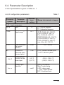
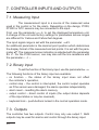
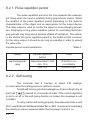
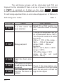
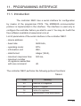
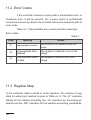
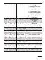
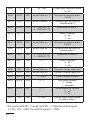
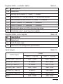
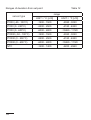
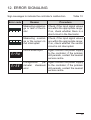
1
TEMPERATURE CONTROLLER 76x34 mm RE01 USER’S MANUAL 1 2 Contents 1.Application......................................................................... 5 2.Controller set.................................................................... 5 3.Fundamental requirements, operational safety.................... 6 4.Assembly............................................................................ 6 4.1Installation of the controller........................................ 6 4.2Electrical connections................................................... 8 4.3Installation recommendations........................................ 8 5.Commencement of operation................................................. 9 6.Operation.......................................................................... 11 6.1Programming the controller’s parameters..................... 12 6.2Programming matrix...................................................... 13 6.3Change of the setting..................................................... 14 6.4Description of parameters............................................. 15 7.Controller inputs and outputs........................................... 20 7.1Measurement input......................................................... 20 7.2Binary input................................................................... 20 7.3Outputs......................................................................... 20 8.Control............................................................................. 21 8.1On-off algorithm........................................................... 21 8.2SMART PID innovative algorithm...................................... 21 8.2.1 Pulse repetition period................................................. 22 8.2.2 Self-tuning.................................................................. 22 8.2.3 Procedure to follow when the PID control is unsatisfactory.... 25 9.Alarm and sound alarm...................................................... 26 10.Additional functions......................................................... 28 10.1 Display of the control signal........................................ 28 10.2 Manual control............................................................ 28 10.3 Factory settings........................................................... 28 3 11.Programming interface..................................................... 29 11.1 Introduction................................................................ 29 11.2 Error codes.................................................................. 29 11.3 Register map................................................................. 29 12.Error signalling.............................................................. 37 13.Technical specification...................................................... 38 14.Controller design code..................................................... 41 The manual applies to the controller with software v1.01 or higher. 4 1. APPLICATION Controller RE01 is designed to control temperature. It cooperates directly with resistance-type sensors Pt100, Pt1000 and NTC. The controller has one output for on-off control and one output for alarm signalling. The on-off control employs the PID or on-off algorithm. For the on-off control, the minimum on and off times for the output may be set. The control output has a changeover contact and allows for the direct control of low-power objects. An innovative SMART PID algorithm is implemented in the controller. In addition, the controller has a binary input to control the controller’s functions and an internal sound signalling device. 2. CONTROLLER SET The delivered controller set is composed of: 1.controller.......................................... 1 piece 2.contact with 7 screw terminals......... 1 piece 3.contact with 3 screw terminals......... 1 piece 4.clamp for on-board mounting........... 4 piece 5.gasket.............................................. 1 piece 6.user’s manual.................................. 1 piece 7.warranty card................................... 1 piece 5 3. BASIC REQUIREMENTS, OPERATIONAL SAFETY In the safety service scope, the controller meets to requirements of the EN 61010-1 standard. Observations Concerning the Operational Safety: • The assembly and installation of electrical connections shall be performed by a person qualified for the assembly of electrical devices. • Check if the connections are made correctly before powering on the controller. • Power off the controller and disconnect measuring circuits before removing the controller’s housing. • The removal of the controller’s housing during the validity of the warranty agreement nullifies the agreement. • The devices is designed for installation and use in industrial, electromagnetic environmental conditions. • The installation should be fitted with a switch or circuit-breaker located near the device, easily accessible to the operator and with appropriate marking. 4. INSTALLATION 4.1. Controller Installation Attach the controller to the board with four screw mounts in line with Fig. 1. The hole in the board should be 71+0.7 x 29+0.6 mm. The board material may be up to 15 mm thick. 6 Fig. 1. Attaching the controller The controller’s dimensions are shown on Fig. 2. Fig. 2. Controller dimensions. 7 4.2. Electrical Connections The controller has two disconnectable strips with screw terminals. One strip allows for the connection of power supply and output with a wire up to 2.5 mm2 in size and the other strip for the connection of input signals with a wire up to 1.5 mm2 in size. Fig. 3. View of the controller’s connection strips. 4.3. Installation recommendations To obtain full resistance to electromagnetic interference, observe the following rules: • do not power the controller from the mains near equipment generating impulse interference and do not use common earthing circuits for them, • use line filters, • measuring signal input wires should be screened twisted pairs and wires for resistance sensor in three-wire systems formed by screened twisted wires with the same length, size and resistance, • all the screens should be earthed or connected to a protective cable, on one side, as close to the controller as possible, • follow the general principle that wires which transmit different signals should run as far from each other as possible (no less than 30 cm) and bundles should cross each other at the angle of 90o. 8 5. Commencement of operation Description of the controller Fig. 4. View of the controller’s front panel. Power on Once powered on, the controller performs a display test, shows re01, software version and then the measured value. The display may show a sign message on irregularities (see Table no. 13). The on-off control algorithm with hysteresis 2.0°C is factory set. Change of the set point To display the set point, press or , the dot for the last digit lights up then. To change the set point, press again or (Fig. 5). The dot flashes to signal the start of change. Accept the new set point with within 30 seconds from the last pressed or ; otherwise the controller changes over to display the measured value with the previously set-up set point. 9 Fig. 5. Changing the set point. 10 6. Operation Fig. 6. Controller operation menu Fig. 6 shows the operation of the controller. 11 6.1. Programming of controller parameters Press and hold for approx. 2 seconds to enter the programming matrix. The programming matrix may be protected with an access code. If a wrong code is inserted, one may only view the settings without changing them. Fig. 7 shows the navigation matrix in the programming mode. To go from one level to another, use or and to select a level, use . Once the level is selected or are used to navigate among parameters. In order to change the parameter setting, follow point Change of the setting. To exit the selected level, go from parameter to parameter u til the symbol [. . .] appears . To exit the programming matrix for the normal and press operation mode, go from level to level until the symbol [. . .] appears and press . Some parameters of the controller may be hidden, depending on the current configuration. The parameters are described in Table no. 1. 30 seconds from the last button pressed, the device returns automatically to the normal operation mode. 12 6.2. Programming Matrix inp Input parameters outp uni t Unit out1 in.ty Input type out2 Output 2 configuration Output parameters Output 1 configuration ctrl Control parameters alg Control algorithm Control type pid pb Proportional band Integration Time constant alar a!sp Absolute alarm 1 set point PID parameters Alarm parameters Set-point value parameters spp spl set point setting lower limit seru Service parameters seCU Access code type ti r-li Line resistance dp Decimal point position spH Binary input function ... Go one level up ... level up Hy Hysteresis Ton Output minimum on time y0 Derivative time constant td Control signal adjustment, for P/PD-type control a!Hy a!lt Alarm 1 hysteresis Alarm 1 memory Toff Output minimum off time to sTlo Lower threshold for self-tuning Yfl ... Sensor failure control signal Go A@lt Go one level up ... Pulse repetition period Go one level up a@sp Deviation from relative alarm 2 set point Absolute alarm 2 set point sTHi Upper threshold for self-tuning a@du a@Hy Alarm 2 hysteresis Alarm 2 memory ... one level up ... set point setting upper limit Go one sTfn bufn Self-tuning function bNin Go one a!du Deviation from relative alarm 1 set point 5Hif Measured value shift level up Buzzer function ... Go one level up ... Exit from menu Fig. 7. Programming matrix 13 6.3. Change of the setting To start changing the parameter setting, press while the parameter name is displayed. Press and to select the setting and press to accept it. A change is cancelled when you press and at the same time or automatically after 30 seconds from the last button pressed. Fig. 8 shows how to change settings. Fig. 8. Changing the settings of numerical and text parameters. 14 6.4. Parameter Description A list of parameters is given in Table no. 1. List of configuration parameters Parameter symbol Parameter description Table 1 Manufacturer setting Range of parameter changes inp – Input parameters unit Unit iNty Input range 1) r-li Line resistance for sensor Pt100 2) 0.0 dp Position of the main input decimal point 1-dp sHif bNin Measured value shift of the main input Binary input function qC pt1 0,0 °C (0,0 °F) none qC: Celsius degrees qf: Fahrenheit degrees p1a: Pt100 (-50...100 °C) p1b: Pt1000 (0...250 °C) p1c: Pt100 (0...600 °C) p10a: Pt1000 (-50...100 °C) p10b: Pt1000 (0...250 °C) p10c: Pt1000 (0...600 °C) ntc: Ntc (-40...100 °C) 0.015.0 0-dp: without decimal point 1-dp: 1 decimal place -100,0...100,0 °C (-180,0...180,0 °F) none: no function stop: control stop rSal: alarm reset out: output control KlCk: keyboard lock 15 outp – Output parameters out1 out2 Output 1 configuration Output 2 configuration y off: switched off Y: control dignal AHi: absolute higher alarm Alo: absolute lower alarm dwHi: relative higher alarm dwlo: relative lower alarm dwin: relative internal alarm dwou: relative external alarm biNd: direct control through binary input biNi: inverse control through binary input off off: switched off AHi: absolute higher alarm Alo: absolute lower alarm dwHi: relative higher alarm dwlo: relative lower alarm dwin: relative internal alarm dwou: relative external alarm biNd: direct control through binary input biNi: inverse control through binary input oNof: on-off control algorithm pid: PID control algorithm ctrl – Control parameters 3) 16 alg Control algorithm oNof type Control type inu Hy Hysteresis 4) 2.0 °C (3.6 °F) 0.2...100.0 oC (0.2...180.0 oF) dir: direct control (cooling) inu: inverse control (heating) Ton Output 1 minimum on time 4) 0 0...999 s Toff Output 1 minimum off time 4) 0 0...999 s sTlo Lower threshold for self-tuning 5) -50.0 °C (-58.0 °F) MIN…MAX 6) sTHi Upper threshold for self-tuning 5) 100.0 °C (212.0 °F) MIN…MAX 6) Yfl 0 Control output control signal for sensor failure 10) 0.0...100.0% pid – PID parameters 7) pb Proportional band 30.0 °C (54.0 °F) 0.1...550.0 oC (0.1...990.0 oF) ti Integration time constant 300 0...9999 s td Derivative time constant 60.0 0.0...2500 s y0 Control signal adjustment, for P or PD-type control 0.0 0...100.0 % to Pulse repetition period 5) 20.0 5.0...99.9 s alar – Alarm parameters 8) a1.sp Set point value for absolute alarm1 0.0 °C (32.0 °F) a1.du Deviation from set point for relative alarm 1 2.0 °C (3.6 °F) See Table no. 3 a1.Hy Hysteresis for alarm 1 1.0 °C (1.8 °F) 0.2...100.0 °C (0.2...180.0 °F) a1.lt Alarm 1 memory off off: disabled on: enabled a#sp Set point for absolute alarm 2 0.0 °C (32.0 °F) a#du Deviation from set point for relative alarm 2 2.0 °C (3.6 °F) MIN...MAX 6) MIN...MAX 6) See Table no. 3 17 a#Hy Hysteresis for alarm 2 a#lt Alarm 2 memory 1.0 °C (1.8 °F) 0.2...100.0 °C (0.2...180.0 °F) off off: disabled on: enabled spp – Set point parameters spl Set point setting lower limit -50.0 °C (-58.0 °F) MIN...MAX 6) spH Set point setting upper limit 100.0 °C (212.0 °F) MIN...MAX 6) seru – Service parameters 0 0...9999 seCU Access code 9) sTfn Self-tuning function on off: locked on: available bwfn Sound signalling function on off: disabled on: enabled Parameter changeable depending on the performance code. Parameter visible only with Pt100-type sensors. 3) Parameter group visible only when the output is set to the control signal. 4) Parameter visible only when the control algorithm is set as on-off. 5) Parameter visible only when the control algorithm is set as PID 6) See Table no. 2. 7) Parameter group visible only when the control algorithm is set as PID. 8) Parameter group visible only when the output is set to alarm. 9) Parameter hidden when parameters are viewed in the read-only mode. 10) Parameter visible only when the output 1 function is set to y: control signal. For control with alg = oNof and Yfl <= 50% the control signal h = 0%, Yfl > 50%, the control signal h = 100%. 1) 2) 18 Measurement ranges for inputs Input / sensor Table 2 MIN MAX °C °F Pt100 thermistor -50 °C -58 °F 100 °C °C 212 °F Pt100 thermistor 0 °C 32 °F 250 °C 482 °F Pt100 thermistor 0 °C 32 °F 600 °C 1112 °F Pt1000 thermistor -50 °C -58 °F 100 °C 212 °F Pt1000 thermistor 0 °C 32 °F 250 °C 482 °F Pt1000 thermistor 0 °C 32 °F 600 °C 1112 °F NTC -40 °C -40 °F 100 °C 212 °F Ranges of deviation from set point sensor type °F Table 3 range UNIT = °C [x10] UNIT = °F [x10] Pt100 (-50...100°C) -150...150 -238...302 Pt100 (0...250°C) -250...250 -418...482 Pt100 (0...600°C) -600...600 -1048...1112 Pt1000 (-50...100°C) -150...150 -238...302 Pt1000 (0...250°C) -250...250 -418...482 Pt1000 (0...600°C) -600...600 -1048...1112 NTC -140..140 -220...284 19 7. CONTROLLER INPUTS AND OUTPUTS 7.1. Measuring Input The measurement input is a source of the measured value used in the control or for the alarm. Depending on the design, Pt100, Pt1000 or NTC sensors may be connected to the input. First, use the parameter unit to set the displayed temperature unit. A change of the unit sets factory settings for parameters whose ranges are different for Celsius and Fahrenheit degrees. The input signal range is set with the parameter iNty. An additional parameter is the decimal point position which determines the display format of the measured and set points. It is set with the parameter dp. The measured value indication is adjusted with the parameter shif. For the Pt100 sensor, one may also set the line resistance with the parameter r-li. 7.2. Binary input To set the function of the binary input, use the parameter bNin. The following functions of the binary input are available: • no function – the status of the binary input does not affect the controller’s operation, • control stop – the control is interrupted, the control output operates as if the sensor were damaged, the alarm operates independently, • alarm reset – resetting the alarm memory, • output control – direct control of inputs (the output status depends of the input status or may be reversed), • keyboard lock – push-buttons locked in the normal operation mode. 7.3. Outputs The controller has two outputs. Control may only use output 1. Both outputs may be used for alarms and control through the binary input. 20 8. CONTROL In the controller you may choose the on-off control or proportional control (PID). For both algorithms you may choose either heating or cooling operation. 8.1. On-off algorithm When the high accuracy of temperature control is not required, especially for objects with a high time constant and low delay, we may employ on-off control with hysteresis. The advantages of this control method is its simplicity and reliability, while the drawback is the generation of oscillation even with low values of hysteresis. Fig. 4. Heating-type output operation method for on-off control In addition, you may set the output minimum on time with the parameter Ton and the output minimum off time with the parameter Toff. 8.2. SMART PID innovative algorithm When the high accuracy of temperature control is required, use the PID algorithm. The employed SMART PID algorithm is characterised with improved accuracy for the extended range of control object classes. The controller is tuned to match the object by way of automatic selection of PID parameters with the self-tuning function or by way of manual setting of the values for proportional, integral and derivative elements. 21 8.2.1. Pulse repetition period The pulse repetition period is the time between the subsequent times when the input is enabled during proportional control. Select the duration of the pulse repetition period depending on the dynamic characteristics of the object and as appropriate for the output device. The relay output is used to control the object in slow-changing processes. Employing a long pulse repetition period for controlling fast-changing periods may bring about adverse effects of oscillation. Theoretically, the shorter the pulse repetition period is, the better control; however, for the relay output, it should be as long as possible in order to extend the relay’s life. Impulse period recommendations Table 4 Output Impulse repetition period Load electromagnetic relay Recommended > 20s min. 10 s 10 A/230 V a.c. or contactor min. 5 s 5 A/230 V a.c. 8.2.2. Self-tuning The controller has a function to select PID settings. In most cases the settings ensure optimum control. To start self-tuning, go to the message tune (according to Fig. 6) and hold pressed for 2 seconds at least. If the control algorithm is set to on-off or the self-tuning function is locked, the message tune is hidden. To carry out the self-tuning properly, the parameters sTlo and sTHi need to be set. Set the parameter sTlo- sTHi to a value corresponding the maximum value measured when the full-power control is on. 22 The lit symbol indicated the active self-tuning function. The self-tuning duration depends on the dynamic characteristics of the object and may take up to 10 hours. During or immediately after self-tuning, overshoots may appear, thus a lower set point should be set if possible. Self-tuning consists of the following stages: Self-tuning process YES Self-tuning completed NO successfully - Calculation and storage of PID settings in non-volatile memory - Start of PID control with new settings - Change to the manual operation mode - The display shows an error code to be acknowledged 23 The self-tuning process will be interrupted and PID settings will not be calculated if there is a loss of power to the controller, if is pressed or if there is the error eS01 , eS02 . In such a case the control is started with the current PID settings. If a self-tuning experiment fails, an error code will appear acc. to Table no. 5. Self-tuning error codes Error code Reason Table 5 How to proceed eS01 eS01 Select PI or PID control, i.e.. P or PD control has the TI element needs to exceed been selected. zero. eS02 Change the temperature set point or parameters sTlo, sTHi. The set point needs to be within the range: (sTlo + 10% of the range … sTHi - 10% of the range) range = sTHi - sTlo Example: sTlo = -50°C, sTHi= 100°C range = 150°C, 10% of the range = 15°C range of the set point (-35°C...135°C) eS03 eS03 eS04 eS04 eS05 eS05 24 Wrong set point. sed. has been pres- The maximum duration of self-tuning has been exceeded. The change-over waiting time has been exceeded. Check if the temperature sensor is located in the right place and if the set point is not set too high for the object. eS06 eS06 Check the sensor’s connection The measurement method. Do not let the overrange of the input has shoot exceed the input’s meabeen exceeded. surement range. eS20 eS20 A very non-linear object which makes it imPerform self-tuning again. If this possible to obtain the does not solve the problem, seright values of PID palect PID parameters manually. rameters or there has been interference. 8.2.3. Procedure to follow when the PID control is unsatisfactory It is best to select PID parameters by changing the value to one that is twice higher or twice lower. Observe the following principles when making changes. a) Stroke slow response: • reduce the proportional band, • reduce the integral and derivative time. b) Overshoots • increase the proportional band, • increase the integral time. c) Oscillations • increase the proportional band, • increase the integral time, • reduce the derivative time. d) Instability • increase the integral time. 25 9. Alarm and sound alarm The controller allows for the setting of up to two alarms. The sound alarm is also available. Alarm types are given in Fig. 5. aLsp absolute higher [AHi] a L d u (+) SP relative lower [dwlo] a L d u (+) SP aLsp absolute lower [Alo] relative higher [ dwHi] relative lower [dwlo] 26 [ dwHi] aLdu aLdu aLdu relative internal [ dwin] Fig. 5. Alarm types relative higher aLdu SP SP a L d u (-) SP a L d u (-) SP relative external [ dwou] The set point for absolute alarms is the measured value determined by the parameter a1sp, (a2sp) and for relative alarms is the control deviation (SP – PV) from the set point - the parameter a1du, (a2du). The alarm hysteresis, i.e. the area around the set point in which the output status is not changed, is determined by the parameter a1Hy, (a2Hy). The sound alarm is active after at least one alarm occurs. The sound alarm may be turned off by setting the parameter bufn to off. You may set the alarm interlock, which means that the alarm status is remembered once the alarm conditions are removed (parameter ax.lt= on). You may reset the alarm memory by pressing and at the same time in the normal operation mode or via the interface or binary input. 27 10. Additional functions 10.1. SMART PID innovative algorithm When you press the display show the value of the control signal (0...100%). The h symbol appears on the first digit. The control signal may be displayed if the parameter out1 is set to y. 10.2. Manual control Manual control enables you to identify, test the object and control it when the sensor is damaged, among other things. To enter the manual control mode, hold while the control signal is displayed. Manual control is indicated by the pulsating LED with the symbol . The controller interrupts the automatic control and starts the manual control of the output. The display shows the value of the control signal preceded by the symbol h. For the with on-off and For with PID and the control, the control to 0% or 100%. may be set control, the control signal may to any value within 0.0...100%. be set To enter the normal operation mode, press same time. signal and at the 10.3. Factory settings You may restore the factory setting by holding and powering on until the word fabr appears in the display. 28 when 11. Programming interface 11.1. Introduction The controller RE01 has a serial interface for configuration by means of the programmer PD14. The MODBUS communication protocol is implemented in the interface. The interface is used only to configure the controller before you start to use it. You may do it with the free software available at www.lumel.com.pl. List of parameters of the serial interface in the controller RE01: - device address: 1, - baud rate: 9600 bit/s, - operating mode: RTU, - information unit: 8N2, - data format: integer (16 bit), - maximum response time: - maximum number of registers read/written with one command: 500 ms, 40. The controller RE01 performs the following protocol functions: Table 6 Code Meaning 03 read out of n-registers 06 write of 1 register 16 write of n-registers 17 identification of the slave device 29 11.2. Error Codes If the controller receives a query with a transmission error or checksum error, it will be ignored. For a query which is synthetically correct but has wrong values, the controller will send a response with an error code. Table no. 7 lists possible error codes and their meanings. Error codes Table 7 Code Meaning reason 01 unacceptable function the function is not handled by the controller 02 unacceptable data address the register’s address is out of the range 03 unacceptable value of data the register’s value is out of the range 11.3. Register Map In the controller, data is stored in 16-bit registers. The number of registers for writing and readout is given in Table no. 8. The „R-” operation stands for the readout possibility, the „-W” operation for the writing possibility and the „RW” operation for the readout and writing possibilities. 30 description 4000 -W 1…3 Command register 1 – restore factory settings (for °C) 2 – restore factory settings (for °F) 3 – reset the alarm memory 4001 R- 100…999 Software version number [x100] 1…3 Controller performance code 1 – Pt100 input 2 – Pt1000 input 3 – NTC input 2.7k register's address parameter range Table 8 operations designation Register map from address 4000 4002 4003 R- 1301…9999 4 older digits of the serial number 4004 R- 1…9999 4 younger digits of the serial number 4005 R- 0…0xFFFF Controller status – description in Table no. 9 4006 R- 0…0xFFFF Error register – description in Table no. 10 Measured value PV 4007 R- as per Table no. 11 4008 RW as per Table no. 11 Set point SP 4009 R- 0…1000 Control signal [% x10] RW 0…1 Unit 0 – Celsius degrees 1 – Fahrenheit degrees 4010 UNIT 31 4011 INPT RW 0…6 Main input type: 0 – Pt100 (-50...100°C) 1 – Pt100 (0...250°C) 2 – Pt100 (0...600°C) 3 – Pt1000 (-50...100°C) 4 – Pt1000 (0...250°C) 5 – Pt1000 (0...600°C) 4012 R-LI RW 0…150 [x10 W] Line resistance 4013 DP RW 0…1 Decimal point position for the main input 0 – no decimal place 1 – 1 decimal place 4014 SHIF RW -1000…1000 [x10 °C] -1800…1800 [x10 °F] Measured value shift for the main input 4015 BNIN RW 0…4 Binary input function 0 – none 1 – control stop 2 – reset of alarms 3 – control of outputs 4 – keyboard lock 4016 OUT1 RW 0…9 Output 1 function 0 – off 1 – control signal 2 – absolute higher alarm 3 – absolute lower alarm 4 – relative higher alarm 5 – relative lower alarm 6 – relative internal alarm 7 – relative external alarm 8 – direct control through binary input 9 – inverse control through binary input 32 4017 OUT2 RW 0…8 Output 2 function 0 – off 1 – absolute higher alarm 2 – absolute lower alarm 3 – relative higher alarm 4 – relative lower alarm 5 – relative internal alarm 6 – relative external alarm 7 – direct control through binary input 8 – inverse control through binary input 4018 ALG RW 0…1 Control algorithm 0 – on-off 1 – PID 4019 TYPE RW 0…1 Control type 0 – direct control – cooling 1 – inverse control – heating 4020 HY RW 2…1000 [x10 °C] 2…1800 [x10 °F] Hysteresis HY 4021 TON RW 0…999 [s] Output 1 minimum on time 4022 TOFF RW 0…999 [s] Output 1 minimum off time 4023 STLO RW as per Table no. 11 Lower threshold for self-tuning 4024 STHI RW as per Table no. 11 Upper threshold for self-tuning 4025 PB RW 1…5500 [x10 °C] 1…9900 [x10 °F] Proportional band PB 4026 TI RW 0…9999 Integral time constant TI [s] 4027 TD RW 0…25000 Derivative time constant TD [s x10] 4028 Y0 RW 0…1000 Control signal adjustment Y0 (for P or PD control) [% x10] 33 1) 4029 TO RW 50…999 Output pulse repetition period [s x10] 4030 A1SP RW as per Table no. 11 Set point for absolute alarm 1 [x10] 4031 A1DV RW as per Table no. 12 Deviation from set point for relative alarm 1 4032 A1HY RW 2…1000 [x10 °C] 2…1800 [x10 °F] Hysteresis for alarm 1 4033 A1LT RW 0…1 Alarm 1 memory 0 – off 1 – on 4034 A2SP RW as per Table no. 11 Set point for absolute alarm 2 [x10] 4035 A2DV RW as per Table no. 12 Deviation from set point for relative alarm 2 4036 A2HY RW 2…1000 [x10 °C] 2…1800 [x10 °F] Hysteresis for alarm 2 4037 A2LT RW 0…1 Alarm 2 memory 0 – off 1 – on 4038 SPL RW as per Table no. 11 Set point change lower limit 4039 SPH RW as per Table no. 11 Set point change upper limit 4040 SECU RW 0…9999 Code of access to menu 4041 STFN RW 0…1 Self-tuning function 0 – locked 1 – unlocked 4042 BUFN RW 0…1 Sound signalling function 0 – off 1 – on 4043 YFL RW 0..1000 Control output control signal for sensor failure 1) For control with alg = oNof and Yfl <= 50% the control signal h = 0%, Yfl > 50%, the control signal h = 100%. 34 Register 4005 – controller status bit description 0-8 Reserved Table 9 9 Binary input status: 0 – open, 1 - closed 10 Self-tuning" 0 – no self-tuning, 1 – active self-tuning 11 Automated/manual control: 0 – auto, 1 – manual 12 Alarm 1 status: 0 – disabled, 1 – enabled 13 Alarm 2 status: 0 – disabled, 1 – enabled 14 Measured value out of the measuring range 15 Controller error – see the error register Register 4006 – error register bit description 0-13 Reserved 9 Out-of-scale input 10 CRC error of configuration parameters Table 10 Input ranges Table 11 sensor type Pt100 (-50...100°C) range UNIT = °C [x10] UNIT = °F [x10] -500...1000 -580...2120 Pt100 (0...250°C) 0...2500 320...4820 Pt100 (0...600°C) 0...6000 320..11120 -500...1000 -580..2120 0..2500 320..4820 0..6000 320..11120 -400...1000 -400..2120 Pt1000 (-50...100°C) Pt1000 (0...250°C) Pt1000 (0...600°C) NTC 35 Ranges of deviation from set point sensor type Table 12 range UNIT = °C [x10] UNIT = °F [x10] Pt100 (-50...100°C) -1500...1500 -2380...3020 Pt100 (0...250°C) -2500...2500 -4180...4820 Pt100 (0...600°C) -6000...6000 -10480...11120 Pt1000 (-50...100°C) -1500...1500 -2380...3020 Pt1000 (0...250°C) -2500...2500 -4180...4820 Pt1000 (0...600°C) -6000...6000 -10480...11120 NTC -1400...1400 -2200...2840 36 12. ERROR SIGNALING Sign messages to indicate the controller’s malfunction Error code Reason Table 13 Procedure Measuring underran- Check, if the input signal values ge or lack of thermi- are within the appropriate range; stor if so, check whether there is a short-circuit in the thermistor. Measuring overran- Check, if the input signal values ge or the sensor cir- are within the appropriate range; cuit interrupted if so, check whether the sensor circuit is not interrupted. Out-of-scale input Again connect the power supply to the controller; if the problem still persists, contact the nearest service centre. Configuration parameter checksum error Again connect the power supply to the controller; if the problem still persists, contact the nearest service centre. eRad eRee 37 13. TECHNICAL DATA Input signals according to Table no. 14 Input signals and measuring ranges Sensor type Pt100 Table 14 Standard Designation Range EN 60751+A2:1997 Pt100 (-50…100 °C) (0…250 °C) (0…600 °C) Pt1000 EN 60751+A2:1997 Pt1000 (-50…100 °C) (0…250 °C) (0…600 °C) NTC NTC 2.7K (-40…100 °C) Sensor line resistance <10 /wire; for the connection, use wires with the same size and length Fundamental error of measurement of the measured value - 0.5% of the measuring range, Measurement time 0.25 s Detection of error in the measuring circuit: Pt100, PT1000, NTC measuring out of range Binary input - voltage binary input, without galvanic insulation on the sensor side, 38 Output types: – output 1 - relay, no-voltage output change-over contact, load capacity 10 A/250 V a.c., 10 A/30 V d.c. minimum 100 thousand change-over cycles for the maximum load – output 2 - relay, no-voltage output normally open contact, load capacity 5 A/250 V a.c., 5 A/28 V d.c. minimum 100 thousand change-over cycles for the maximum load Output one operation method: - inverse - direct for heating for cooling Rated operating conditions: - supply voltage - supply voltage frequency - ambient temperature - storage temperature - air relative humidity - pre-heating time - operating position 230 V a.c. 10% 50/60 Hz 0…23…50 °C -20…+70 °C < 95 % (no condensation of steam) 30 min any Power input < 4 VA Weight< 0.25 kg 39 Protection grade ensured by the casing acc. to EN 60529 - from the frontal plate IP65 - from the terminal side IP20 Additional errors in rated operating conditions caused by: - a change in the line resistance of the thermal resistance sensor 50% of the fundamental error value - a change in the ambient temperature 100% of the fundamental error value /10 K Safety requirements acc. to EN 61010-1 1) - insulation between circuits basic - installation category III, - pollution level 2, - maximum phase-to-earth operating voltage: - for supply circuits, output 300 V - for input circuits 50 V - altitude above sea level < 2000 m Electromagnetic compatibility - noise immunity acc. to EN 61000-6-2 standard - noise emissions acc. to EN 61000-6-4 standard 40 14. CONTROLLER VERSION CODES The coding is given in Table no. 15. Controller RE01 - X X Table 15 X X Input 1: Pt100 1 Pt1000 2 NTC 2,7k 3 Version: 00 standard XX custom-made2) Language: polish P english E X other2) Acceptance tests: without extra quality requirements 0 with an extra quality inspection certificate 1 acc. to customer’s request 2) X 1) the code will be established be the manufacturer after agreeing with the manufacturer. 2) Only 41 42 43 Export department: tel.: (+48 68) 45 75 139, 45 75 233, 45 75 321, 45 75 386 fax.: (+48 68) 32 54 091 e-mail: [email protected] 44 RE01-09A LUMEL S.A. ul. Słubicka 1, 65-127 Zielona Góra, POLAND tel.: +48 68 45 75 100, fax +48 68 45 75 508 www.lumel.com.pl, e-mail: [email protected]