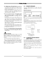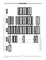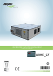
1
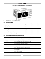
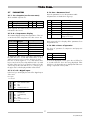
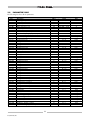
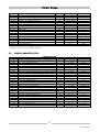
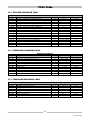
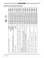
CLS-CLH control
2 Compressors
ELECTRONIC
SERVICE MANUAL
CLS/CLH 09/05
CLS-CLH ELECTRONIC CONTROL
1
TECHNICAL CHARACTERISTICS
1.1
SPECIFICATIONS
Typical
12V~
50Hz/60Hz
11VA
1
IPO front panel
25 °C
30%
25 °C
30%
Supply voltage
Supply frequency
Capacity
Insulation class
Protection degree
Room temperature
Room humidity (non-condensing)
Storage room temperature
Storage room humidity (non-condensing)
1.2
Min.
10.8V~
–
–
–
–
0 °C
10%
-20 °C
10%
Max.
13.2V~
–
–
–
–
60 °C
90%
85 °C
90%
ELECTRO-MECHANICAL CHARACTERISTICS
Digital outputs 120/240 V
Analog outputs
Analog inputs
Digital inputs
Terminals and connectors
Display and led
Keys
Serial lines
• n° 8 relays 5 A resistive; 1/4 hp 230 VAC; 1/8 hp 125 VAC (basic)
The total current on relays shall not exceed 10A
• n° 2 relays 5 A resistive; 1/4 hp 230 VAC; 1/8 hp 125 VAC (expansion)
• n° 2 configurable triac outputs or 4-20 mA
• n° 4 NTC R25 10KΩ
• n° 2 configurable inputs 4-20 mA / NTC R25 10KΩ
• n° 11 voltage-free digital inputs (basic)
• n° 4 voltage-free digital inputs (expansion)
• n° 1 HV 10-way connector pitch 7.5
• n° 2 LV 16-way connectors pitch 4.2, AWG 16-28
• n° 1 p2,5 5-way connector, with remote control and memory card, AWG 24-30
• n° 1 20-way connector, connection expansion
• n° 1 3-way screw terminal for remote keyboard
• n° 3 digits + sign
• n° 5 red LED’s
• n° 2 keys
• n° 1 serial line 9600
• n° 1 serial line 2400
2
CLS/CLH 09/05
Transformer
2
This appliance must be powered by a suitable trans-former, having the characteristics listed below:
• Primary voltage:
230V~±10%, 110V~±10%
• Secondary voltage:
12V~
• Supply frequency:
50 Hz; 60 Hz
• Power:
11VA
The interface, consisting of the front of the appliance,
allows you to carry out any operation with this tool, and
in particular:
• to set the operating mode
• o to control alarm situations
• to check the state of resources
1.3
Keyboard
DIMENSIONS
• Dimensions:
• Container:
• Mounting:
USER INTERFACE
1 2
Front 76x34, depth 58 mm
plastic resin
PC+ABS,extinction degree Vo
panel – on a 71x29 mm hole
mode
set
on off
Front panel of the appliance
71 x 29 mm
2.1
KEYS
Mode
Selects the operating mode:
• if the heat mode is enabled, pressing this
key results in the following sequence:
Stand-by ocooling oheating ostand-by
• if the heat mode is not enabled:
Stand-by ocooling ostand-by
In the menu mode, this key becomes the
SCROLL UP or UP value (increment) key.
mode
1.4
STANDARDS
The product conforms to the following EC Directives:
• 73/23/EC Directive and subsequent amendments
• 89/336/EC Directive and subsequent
amendments and complies with the following harmonised Standards:
• Low Voltage: EN60335 as applicable
• Emission: EN50081-1 (EN55022)
• Immunity: EN50082-1 (IEC 1000-4-2/3/4/5)
On-Off Alarm Reset
Resets the alarms, and turns the appliance
on/off.
Press it once to reset all manual alarms that
have not been activated.
Hold this key down for 2 seconds, the
appliance switches from ON to OFF or
from OFF to ON. When OFF, only the decimal point of the display remains lighted.
In the menu mode, this key becomes the
SCROLL DOWN or DOWN (decrement)
key.
on off
mode
set
on off
On-off mode combination
The “mode” and “on-off” keys are pressed
at the same time.
Press and release these keys in 2 seconds
to go to the lower level in the display
menu. Hold down both keys for more than
2 sec-onds to go to the upper level.
If you are displaying the last level of a
menu, pressing and releasing this key in 2
seconds allows you to go to the upper
level.
3
CLS/CLH 09/05
2.2
DISPLAYED DATA
2.3
This device can give any type of information on its status,-configuration and alarms, through a display and the
LED's on its front panel.
Before starting this appliance:
1) Turn on the master switch of the supply line.
2) For a perfect heating of the oil in the compressor's
sump and for a proper removal of the refrigerant contained in the oil, the operation described in point 1)
above should be carried out several hours before the
actual start-up of the appliance.
2.2.1 DISPLAY
The following data appear in normal display mode:
• the control temperature, in tenths of a
degree Celsius with decimal point or
Fahrenheit without decimal point.
• The alarm code, if at least one of them is
enabled. If more alarms are activated,
the first one is displayed, according to
the Alarm Table.
• If the thermoregulation is not based on
analog inputs and depends on the status
of a digital input (ST1 or ST2, configured
as digital inputs) the “On” or “Off” label
is displayed according to the thermoregulator state (on/off).
• In the menu mode the display is a function of the position.
• If only the decimal point is lighted, the
control is not activated. Press the key
2.4
STARTING AND USING THE UNIT
In order to use this unit properly and in full safety, carefully read and understand the following instructions.
1) To start up the unit, press the on off key for 5 seconds;
if you do this during operation, the unit will stop.
When the appliance is off, the display of the control
system shows a red "-" or the E00 message, if a
Start/Stop remote contact is provided. While the unit
is running, the display shows the temperature of the
return water.
mode
2) If the unit is of the heat pump type, the
key
makes it possible to select the cooling mode or the
heating mode.
Pressing this key makes the mode cyclically switch
from stand-by to cooling, heating, stand-by etc. The
cooling mode is indicated by the lighting up of the
LED under the ideogram
, while the heating mode
is indicated by the lighting up of the LED under the
ideogram
.
on off
for 5 seconds to activate the cotrol, once the machine has been powered.
You will display the value of the sensor
of the water entering the evaporator
(ST1). To turn off the control, press the
key for 5 seconds.
3) To modify the set point, press both keys at the same
time. When the “Set” message appears on the display, the operation must be repeated to go to the
next level. Scroll the text on the display up or down,
so that the “Coo” and “HEA” messages appear alternatively. The heating set point can be modified by
pressing both keys at the same time, so as to go to
the next level.
The shop setting will thus appear (12 °C). This setting
can be increased or decreased by scrolling the value
up or down with the relevant keys.
Once the desired value is displayed, simply press
both keys for 2 seconds to accept it and to go back
to the previous level.
Scroll the text on the display until the “HEA” message
appears and the heating set point can be modified
by following the procedure adopted to modify the
cooling set point.
Once the set points have been modified, you can go
back to the first level by holding both keys down for
2 seconds, as described in the paragraph “User
interface”.
Led 1 compressor 1.
• ON if compressor 1 has been activated
• OFF if compressor 1 is not activated
Defrost
Signalled by the slow blinking of both the
LED's of the compressors
Resistor /boiler LED
• ON if the internal antifreeze resistor or
the boiler are on
• OFF if the internal antifreeze resistor or
the boiler are off
Heating LED
• ON if the device is in heating mode (the
reversal valve is not excited)
Cooling LED
• ON if the controller is in cooling mode
(the reversing valve is excited)
If the HEAT and COOL LED's are off, the controller is in
the STAND-BY mode.
4
CLS/CLH 09/05
BEFORE START-UP
2.5
4) To display other useful temperatures), go to level 1
as described above and then scroll the display until
“tp” appears; then repeat the procedure, so as to
reach the lower level. At this point, scroll the display
until t01, t02, t03 appears.
If you go to the next level while t02 appears and the
leaving water temperature is displayed, while if you
repeat the operation when tp03 appears, the coil's
surface temperature is displayed.
REMOTE KEYBOARD
The remote display keyboard is a perfect copy of the
information displayed about the instrument, and has the
same LED's:
Remote keyboard
5) The unit is shop-preset for the summer/winter switch
over through the keyboard. If a summer/winter
switch over remote contact is provided, switch the
H49 software parameter to reconfigure the unit
accordingly.
To do this, press the two keys at the same time to go
to the upper level and then scroll the display until
“Par” appears. Press both keys at the same time
again, so as to go to the upper level, and then scroll
the display until “Cnf” appears and repeat the operation to go to the upper level.
Once this level is reached, scroll the display until
“H49” appears; at this point press the two keys
again to reach the lower level.
At this point modify the setting of the parameter (0 to
1). Confirm the change and repeat the procedure
(holding the keys down for 2 seconds each time), so
as to go back to the first level.
The functions are identical to those listed in the key and
display section.
The only difference consists in the use of the UP and
DOWN keys (to increase/decrease the value), separated by the MODE and ON/OFF keys.
The connection to the device is as follows:
Connection
6) In case of summer/winter switch over through a
remote contact, the unit works in cooling mode when
the contact is closed and in heating mode when the
contact is open.
Wire Color
24 - Blu
25 - Red
26 - Black
IMPORTANT
If the unit is powered with 3-phase voltage, it is essential
that the compressor turn in the exact direction. The
direction of rotation of scroll compressors is forced.
The direction of rotation is wrong when, while the unit is
running:
• you hear an anomalous noise of the compressor
• there is not a proper differential between the discharge and the suction pressures (i.e. if the discharge
pressure is slightly higher than the suction pressure).
If you exchange the connections of two of the three
phases, the compressor inverts the direction of rotation
and these phenomena disappear.
2.6
PARAMETER PROGRAMMING –
MENU LEVELS
The parameters of the device can be modified via
Personal Computer (through the relevant software, interface module and adequate cables) or via keyboard.
In this case, the access to the different parameters is
organized in sub-levels, that can be accessed by pressing the “mode” and "on-off” keys at the same time (see
above).
Each menu level is identified by a mnemonic code that
appears on the display.
The structure is organized in the manner described in
the following diagram:
5
CLS/CLH 09/05
6
CLS/CLH 09/05
Hours of operationOHr
Password Pss
Par. index d01...
Par. index d01...
Not used
Defrosting par. dFr
Expansion par. ESP
Free cooling SPL
No. of hours
No. of hours
Compr. hours: OH1.. OH4
Pump hours: OHP
Password value
Par. index r01...
Antifreeze par. Fro
Ventilation par. FAn
Par. index P01...
Par. index F01...
Compressor par. CP
Pump par. PUP
Par. index C01...
Configuration par. CnF
Par. index A01...
Par. index H01...
Input code 01 ...11
Digital inputs Id
Alarm par. ALL
Digital input value
Activated alarm code E00
Alarms Err
Parameters PAr
Analog input value
Input code t01 ...t06
Analog inputs TP
Set cooling value
Level 3
Set heating value
Label set cooling Coo
Level 2
Label set heating HEA
Set point SEt
Level 1
4”
To store the set data, repeat the operations carried out to enter the parameters, but in reverse, until the initial display;
in this way you can also store the data.
Regulation level
alarm activated
Level 0
2”
To enter these parameters, hold down the “Mode - On-Off” keys at the same time for the seconds indicated
below:
Parameter value
Parameter value
Parameter value
Parameter value
Parameter value
Parameter value
Parameter value
Parameter value
Level 4
2.7
PARAMETERS
2.7.4 Par = Parameter level
Enter the parameter list. See the parameter table.
2.7.1 Set = Setpoint (see the tree menu)
All parameters are divided into 8 groups:
The 2 available setpoints are:
Set
Meaning
Min
Max
Coo Cooling Setpoint
7.0
25.0 10.0
I HEA Heating Setpoint
25.0 47
Standard
40.0
The 2 setpoints are under Set, by scrolling the menu as
indicated for the sensors.
2.7.2 tP = Temperature display
The terminal displays always the temperature of the sensor at the inlet of the evaporator. The other sensors are:
Cnf
parameters H
machine configuration
CP
parameters C
compressor
FAn
parameters F
fans
ALL
parameters A
alarms
PUP
parameters P
pump
Fro
parametersi r
antifreeze/additional resistors
dFr
parameters d
defrosting cycle
ESP
parameters N card configuration
expansion 2 relays
2.7.5 PSS = Password
Symbol used sensor - wiring
for the control diagram
t01
BTin
meaning
Temp in evaporator
t02
1BT-out
Temp. at the outlet of evap 1
2.7.6 OHr = Hours of operation
t03
1BT-coil
Temp of coil 1
The hours of operation of compressors and pump are
displayed
t05
2BT-out
Temp at the outlet of evap 2
t06
2BT-coil
Temp of coil 2
Enter password 177 to display all the parameters from
the parameter list.
t04
To display the other sensors, press the 2 arrow keys at
the same time for 1 second and release them, so as to
shift from level 0 to level 1. Use the arrows to go to tP.
Press the 2 arrows again for 1 sec. and release these
keys to enter level 2 (sensor list) and then level 3 (to read
the value of the sensors). To go back to level 0, press the
2 arrow keys at the same time for 3 sec., until you go to
the upper level on the display and then release them.
OH1
Hours of compr. 1
OH3
Hours of compr. 2
OHP
Pump hours
To reset the displayed counter, press the on/off key for
2 seconds while the hours are being displayed. After
999 hours, the decimal point is displayed and the numbering is expressed in hours/100.
2.7.3 Id = Id = Digital inputs
In this level you can display the state of the digital inputs
of the card.
CONNECTOR B
CONNECTOR A
0 = open
1 = closed
ID1
ID2
ID3
ID4
ID5
flow meter/ext consent
fans' thermal switch
LP1
HP1
thermal switch C1
ID6
ON/OFF (can be enabled)
Heat/Cold
(closed=heat)
LP2
HP2
thermal switch C2
free
ID7
ID8
ID9
ID10
ID11
7
CLS/CLH 09/05
2.8
PARAMETER TABLE
The following list shows all the parameters.
Par.
Pa G01
Pa G02
Pa H01
Pa H02
Pa H03
Pa H04
Pa H05
Pa H06
Pa H07
Pa H08
Pa H09
Pa H10
Pa H11
Pa H12
Pa H13
Pa H14
Pa H15
Pa H16
Pa H17
Pa H18
Pa H19
Pa H20
Pa H21
Pa H22
Pa H23
Pa H24
Pa H25
Pa H26
Pa H27
Pa H28
Pa H29
Pa H30
Pa H31
Pa H32
Pa H33
Pa H34
Pa H35
Pa H36
Pa H37
Pa H38
Pa H39
Pa H40
Pa H41
Pa H42
Pa H43
Pa H44
Pa H45
Pa H46
Pa H47
Pa H48
Pa H49
Pa H50
Pa H51
CONFIGURATION PARAMETERS*
Description
Value
"Cooling" set-point
10
"Heating" set-point
40
Max. set-point in heat
47
Min. set-point in heat
25
Max. set-point in cool
25
Min. set-point in cool
7
Number of circuits of the machine
2
Number of compressors per circuit
1
Number of capacity steps per compressor
0
Compressors' start-up sequence
0
Circuit balancing
0
Presence of the heat pump
1
Configuration ST1
1
Configuration ST2
1
Configuration ST3
1
Configuration ST4
0
Configuration ST5
1
Configuration ST6
1
Full scale pressure value
300
Polarity ID1 ID2 ID3 ID4
15
Polarity ID5 ID6 ID7 ID8
15
Polarity ID9 ID10 ID11 ST4
15
Polarity ST1
0
Polarity ST2
0
Configuration ID1
1
Configuration ID2
8
Configuration ID3
12
Configuration ID4
10
Configuration ID5
4
Configuration ID6
2
Configuration ID7
3
Configuration ID8
13
Configuration ID9
11
Configuration ID10
6
Configuration ID11
0
Configuration ST4 (if digital input)
0
Configuration of relay 2
10
Configuration of relay 3
7
Configuration of relay 4
5
Configuration of relay 5
1
Configuration of relay 6
0
Configuration of relay 7
3
Polarity RL2
0
Polarity RL3
0
Polarity RL4
0
Polarity RL5
1
Alarm relay polarity
0
Output configuration - fan 1
0
Output configuration - fan 2
0
Free
0
Selection of the operating mode
0
Enable the dynamic set-point
0
Offset in cooling - dynamic set-point
8
8
CLS/CLH 09/05
Limits
7 ÷ 25
25 ÷ 47
Pa H02 ÷ 90.0
-40.0 ÷ Pa H01
Pa H04 ÷ 90.0
-40.0 ÷ Pa H03
0÷2
0÷4
0÷3
0÷1
0÷1
0÷1
0÷4
0÷2
0÷5
0÷3
0÷1
0÷4
0 ÷ 350
0 ÷ 15
0 ÷ 15
0 ÷ 15
0÷1
0÷1
0 ÷ 22
0 ÷ 22
0 ÷ 22
0 ÷ 22
0 ÷ 22
0 ÷ 22
0 ÷ 22
0 ÷ 22
0 ÷ 22
0 ÷ 22
0 ÷ 22
0 ÷ 22
0 ÷ 11
0 ÷ 11
0 ÷ 11
0 ÷ 11
0 ÷ 11
0 ÷ 11
0÷1
0÷1
0÷1
0÷1
0÷1
0÷1
0÷1
0÷1
0÷1
0÷1
-50.0 ÷ 80.0
Unit
°C
°C
°C
°C
°C
°C
Num
Num
Num
Flag
Flag
Flag
Num
Num
Num
Num
Num
Num
kPa*10
Num
Num
Num
Flag
Flag
Num
Num
Num
Num
Num
Num
Num
Num
Num
Num
Num
Num
Num
Num
Num
Num
Num
Num
Flag
Flag
Flag
Flag
Flag
Flag
Flag
Flag
Flag
Flag
°C
Pa
Pa
Pa
Pa
Pa
Pa
Pa
Pa
Pa
Pa
Pa
Pa
Pa
Pa
Pa
Pa
Pa
Pa
H52
H53
H54
H55
H56
H57
H58
H59
H60
H61
H62
H63
H64
H65
H66
H67
H68
H69
Offset in heating - dynamic set-point
Set ext. T. in cooling - dynamic set-point
Set ext. T. in heating - dynamic set-point
Delta T. ext. - dynamic set-point, cooling
Delta T. ext. - dynamic set-point
Offset ST1
Offset ST2
Offset ST3
Offset ST4
Offset ST5
Offset ST6
0=50 Hz 1=60 Hz
0=°C 1=°F
Serial address - family
Serial address - device
User password
Parameter key password
Keyboard presence
40
35
-5
25
28
0.0
0.0
0.0
0.0
0.0
0
0
0
0
0
177
2
1
-50.0 ÷ 80.0
-127 ÷ 127
-127 ÷ 127
-50.0 ÷ 80.0
-50.0 ÷ 80.0
-12.7 ÷ 12.7
-12.7 ÷ 12.7
-12.7 ÷ 12.7
-12.7 ÷ 12.7
-12.7 ÷ 12.7
-12.7 ÷ 12.7
0÷1
0÷1
0 ÷ 14
0 ÷ 14
0 ÷ 255
0 ÷ 255
0÷1
°C
°C
°C
°C
°C
°C
°C
°C/10-Kpa*10
°C
°C
°C/10-Kpa*10
Flag
Flag
Num.
Num.
Num.
Num.
Flag
* If the parameters of this category are modified, the controller must be turned off and then on again after each
change, in order to ensure a proper operation.
2.9
ALARM PARAMETER TABLE
Par.
Pa A01
Pa A02
Pa A03
Pa A04
Pa A05
Pa A06
Pa A07
Pa A08
Pa A09
Pa A10
Pa A11
Pa A12
Pa A13
Pa A14
Pa A15
Pa A16
Pa A17
Pa A18
Pa A19
Pa A20
Pa A21
Pa A22
Pa A23
Pa A24
Pa A25
Pa A26
PARAMETERS ALARM
Description
Bypass of LP pressure switch from compressor
No. of interventions/hour LP
By pass of pressure switch from pump activation
Duration of flow meter input activated
Duration of flow meter input deactivated
No. of interventions/hour flow meter
Bypass of compressor's thermal devices from compressor activation
No. of interventions/hour of the compressor's thermal devices
No. of interventions/hour of the fan's thermal devices
Bypass of antifreeze alarm from ON-OFF
Antifreeze alarm activation set
Antifreeze alarm hysteresis
No. of interventions/hour of antifreeze alarm
HP activation set for analog input
HP hysteresis for analog input
Bypass: activation LP for analog input
Set: activation LP for analog input
LP hysteresis for analog input
No. of interventions/hour LP analog input
Uncharged machine differential
Uncharged machine bypass
Uncharged machine time
Enable the uncharged machine alarm
Enable min. alarm in defrosting
Set over-temperature ST1
Duration ON over-temperature 120
Value
40
3
5
2
2
0
0
1
1
0
4
2.0
1
600
20
22
-500
10
4
20
30
30
0
0
25
120
Limits
0 ÷ 255
0 ÷ 255
0 ÷ 255
0 ÷ 255
0 ÷ 255
0 ÷ 255
0 ÷ 255
0 ÷ 255
0 ÷ 255
0 ÷ 255
-127 ÷ 127
0 ÷ 25.5
0 ÷ 255
0 ÷ 900
0 ÷ 255
0 ÷ 255
-500 ÷ 800
0 ÷ 255
0 ÷ 255
0 ÷ 255
0 ÷ 255
0 ÷ 255
0÷1
0÷1
0 ÷ 255
0 - 255
Unit
Seconds
Num
Seconds
Seconds
Seconds
Num
Seconds
Num
Num
Minutes
°C
°C
Num
°C/10-Kpa*10
°C/10-Kpa*10
Seconds
°C/10-Kpa*10
°C/10-Kpa*10
Num
°C
Minutes
Minutes
Flag
Flag
°C
S*10
9
CLS/CLH 09/05
2.10 COMPRESSOR PARAMETER TABLE
Par.
Pa C01
Pa C02
Pa C03
Pa C04
Pa C05
Pa C06
Pa C07
Pa C08
PARAMETERS COMPRESSOR
Description
Value
Start/Stop safety time
9
Start/Start safety time Pa C03 Thermoregulator hysteresis (cooling)
36
Thermoregulator hysteresis (cooling)
2,5
Thermoregulator hysteresis (heating)
2,5
Regulation step intervention delta
2,5
Interval: compressor - compressor intervention
10
Interval: compressor – compressor turning off
0
Interval: capacity step intervention
0
Limits
0 ÷ 255
0 ÷ 255
0 ÷ 25,5
0 ÷ 25,5
0 ÷ 25,5
0 ÷ 255
0 ÷ 255
0 ÷ 255
Unit
Seconds*10
Seconds*10
°C
°C
°C
Seconds
Seconds
Seconds
Limits
0÷2
0 ÷ 255
0 ÷ 100
0 ÷ 255
0÷1
0 ÷ 100
0 ÷ 100
-500 ÷ 800
0 ÷ 255
0 ÷ 255
0 ÷ 255
0 ÷ 255
0 ÷ 100
-500 ÷ 800
0 ÷ 100
0 ÷ 100
-500 ÷ 800
0 ÷ 255
0 ÷ 100
-500 ÷ 800
0 ÷ 255
0÷1
-500 ÷ 800
0 ÷ 255
0 ÷ 255
Unit
Num
Seconds/10
µSeconds*200
µSeconds*200
Flag
%
%
°C/10-Kpa*10
°C/10-Kpa*10
°C/10-Kpa*10
°C*/10-Kpa*10
Seconds
%
°C/10-Kpa*10
%
%
°C/10-Kpa*10
°C/10-Kpa*10
%
°C/10-Kpa*10
Seconds
Flag
°C/10-Kpa*10
°C/10-Kpa*10
Seconds
Limits
0÷1
0 ÷ 255
0 ÷ 255
Unit
Flag
Seconds
Seconds
2.11 VENTILATION PARAMETER TABLE
Par.
Pa F01
Pa F02
Pa F03
Pa F04
Pa F05
Pa F06
Pa F07
Pa F08
Pa F09
Pa F10
Pa F11
Pa F12
Pa F13
Pa F14
Pa F15
Pa F16
Pa F17
Pa F18
Pa F19
Pa F20
Pa F21
Pa F22
Pa F23
Pa F24
Pa F25
PARAMETERS VENTILATION
Description
Value
Fan outlet mode
2
Fan start time
30
Fan offset
8
Start-up pulse duration
3
Operation requested by the compressor
0
Minimum speed in cool
20
Max. silent speed in cool
100
Set temp./pressure, min. fan speed in cool
100
Prop. band in cool
50
Cut-off differential
30
Cut-off hysteresis
20
Cut-off by-pass time
30
Max. speed in cool
100
Set temp./pressure, max. fan speed in COOL
800
Min. speed in heat
100
Max. silent speed in heat
100
Set temp./pressure, min. fan speed in heat
10
Prop. band in heat
50
Max. speed in heat
100
Set temp./pressure, max. fan speed in heat
-200
Pre-ventilation in cooling mode
0
Single or separated ventilation
1
Set temp./pressure, fan activation in defrosting
800
Fan activation hysteresis in defrosting
0
Fan time (post-defrosting)
0
2.12 PUMP PARAMETER TABLE
PUMP PARAMETERS
Par.
Pa P01
Pa P02
Pa P03
Description
Pump operating mode
Delay: pump ON compressor ON
Delay: compressor OFF pump OFF
Value
0
20
15
10
CLS/CLH 09/05
2.13 RESISTOR PARAMETER TABLE
Par.
Pa r01
Pa r02
Pa r03
Pa r04
Pa r05
Pa r06
Pa r07
Pa r08
Pa r09
Pa r10
Pa r11
Pa r12
Pa r13
Pa r14
Pa r15
Pa r16
Pa r17
RESISTOR PARAMETERS
Description
Value
Resistor configuration in defrosting mode
0
Resistor (on) configuration in cooling mode
0
Resistor (on) configuration in heating mode
0
Configuration of resistor regulating sensor 1
2
Configuration of resistor regulating sensor 2
3
Resistor configuration - OFF or STAND-BY
1
Set point of resistor 1 in heating mode
5
Set point of resistor 1 in cooling mode
5
Max. resistor set
30
Min. antifreeze resistor set
-10
Antifreeze resistor hysteresis
2.0
External antifreeze resistor set point
1
Set point of resistor 2 in heating mode
5
Set point of resistor 2 in cooling mode
5
Enable resistors in integration
0
Integration resistor 1 activation
2.0
Integration resistor 2 activation
2.0
Limits
0÷1
0÷1
0÷1
0÷3
0÷3
0÷1
Pa 10 ÷ Pa 09
Pa 10 ÷ Pa 09
Pa 10 ÷ 127
-127 ÷ Pa 09
0 ÷ 25,5
Pa 10 ÷ Pa 09
Pa 10 ÷ Pa 09
Pa 10 ÷ Pa 09
0÷1
0 ÷ 25.5
0 ÷ 25.5
Unit
Flag
Flag
Flag
Num
Num
Flag
°C
°C
°C
°C
°C
°C
°C
°C
Flag
°C
°C
Limits
0÷1
-500 ÷ 800
0 ÷ 255
-500 ÷ 800
0 ÷ 255
0 ÷ 255
0 ÷ 255
0 ÷ 255
0÷3
0÷3
0 ÷ 255
Unit
Flag
°C/10 - kPa*10
Minutes
°C/10 - kPa*10
Minutes
Seconds
Seconds
Secondi *10
Num
Num
Seconds
Limits
0÷1
0 ÷ 19
0 ÷ 19
0 ÷ 19
0 ÷ 19
0 ÷ 11
0 ÷ 11
Unit
Flag
Num
Num
Num
Num
Num
Num
2.14 DEFROSTING PARAMETER TABLE
Par.
Pa d01
Pa d02
Pa d03
Pa d04
Pa d05
Pa d06
Pa d07
Pa d08
Pa d09
Pa d10
Pa d11
DEFROSTING PARAMETERS
Description
Value
Enable defrosting
1
Defrosting start temperature/pressure
0
Defrosting interval
45
Defrosting end temperature/pressure
60
Max. defrosting time
5
Compressor-reversing valve waiting time
0
Dripping time
0
Delay between circuit defrosting
0
Defrosting circuit 1 outlet sensor
1
Defrosting circuit 2 outlet sensor
3
Compressor start-up delay in defrosting
0
2.15 EXPANSION PARAMETER TABLE
EXPANSION PARAMETERS
Par.
Pa N01
Pa N02
Pa N03
Pa N04
Pa N05
Pa N06
Pa N07
Description
Polarity ID12 ID13 ID14 ID15
Configuration ID12
Configuration ID13
Configuration ID14
Configuration ID15
Relay configuration 9
Relay configuration 10
Value
15
0
0
0
0
0
0
11
CLS/CLH 09/05
3
ALARM TABLE
CODE
SIGNAL
DESCRIPTION
RESET
E00
Remote Off
• Turns off all the users;
• Is activated by the digital input configured as “remote ON-OFF” (see digital
inputs)
Auto
E01
High pressure
in circuit 1
• Turns off all the compressors of circuit 1;
• Is activated by the digital input configured as “High pressure in circuit 1"
(see digital inputs)
Man
E02
Low pressure
in circuit 1
• Turns off the compressors and the fans of the condenser if the separate
condensation has been set for the 2 circuits (see single or separate condensation);
• Is activated by the digital input configured as “Low pressure in circuit 1”
(see digital inputs);
• Automatically reset until the number of interventions/hour is equal to the
value set by parameter Pa A02; in this case it becomes manual;
• Disabled during the Pa A01 time counting, due to the turning on of a
compressor or by the reversal of the 4-way valve (reversing valve) of circuit 1
Auto/Man
E03
Thermal
protection
of compressor 1
• Turns off the compressor 1;
• Is activated by the digital input configured as “Thermal devices of compressor 1” (see digital inputs);
• Automatically reset until the number of interventions/hour is equal to the
value set by parameter Pa A07; in this case it becomes manual;
• Disabled during the Pa A08 time counting, due to the turning on of the
compressor
Auto/Man
E04
Thermal
protection
of the condenser's
fans - circuit 1
• Turns off the fans and compressors of circuit 1; if the single condensation
is set for the 2 circuits (see single or separate condensation) the compressors of circuit 2 are locked as well;
• Is activated by the digital input configured as “Thermal devices of the
fan, circuit 1” (see digital inputs);
• Automatically reset until the number of interventions/hour is equal to the
value set by parameter Pa A09; in this case it becomes manual;
Auto/Man
E05
Antifreeze circuit 1
• Turns off the fans and the compressors;
• Is enabled if the analog sensor ST2 (see analog inputs) is configured as
antifreeze sensor (Pa H12=1);
• Is activated when the sensor ST2 detects a value lower than Pa A11;
• Is disabled if the sensor ST2 detects a value above Pa A11 + Pa A12;
• Automatically reset until the number of interventions/hour is equal to the
value set by parameter Pa A13; in this case it becomes manual;
• Is disabled during the Pa A10 time counting by the turning on of Energy
400 by the ON-OFF key (see keyboard) or by the ON-OFF digital input
(see the digital inputs) or when the heating mode is enabled
Auto/Man
E06
Failure
of sensor ST2
• Turns off all the users;
• Is enabled if the sensor ST2, configured as analog input, is short-circuited
or cut-out or when the sensor limits are exceeded (-50 °C..100 °C)
Auto
E07
Failure
of sensor ST3
• Turns off all the users;
• Is enabled if the sensor ST3, configured as analog input, is short-circuited
or cut-out or when the sensor limits are exceeded (-50 °C..100 °C)
Auto
E21
High pressure circuit 2
• Turns off the compressors of circuit 2;
• Is activated by the digital input configured as “High pressure - circuit 2"
(see digital inputs)
Man
12
CLS/CLH 09/05
CODE
SIGNAL
DESCRIPTION
RESET
E22
Low pressure
circuit 2
• Turns off the compressors of circuit 2 and the condenser's fans if the separate condensation for the 2 circuits has been set (see single or separate
condensation);
• Is activated by the digital input configured as “Low pressure – circuit 2”
(see digital inputs);
• Automatically reset until the number of interventions/hour is equal to the
value set by parameter Pa A02; in this case it becomes manual;
• Is disabled during the Pa A01 time counting by the turning on of a compressor or by the reversal of the 4-way valve (reversing valve) of circuit 1
Auto/Man
E25
Antifreeze circuit 2
• Turns off the fans and the compressors;
• Is enabled if the ST5 analog sensor (see analog inputs) is configured as
antifreeze sensor (Pa H15=1);
• Is activated when sensor ST5 detects a value lower than Pa A11;
• Is disabled if sensor ST5 detects a value higher than Pa A11 + Pa A12;
• Automatically reset until the number of interventions/hour is equal to the
value set by parameter Pa A13; in this case it becomes manual;
• Is disabled during the Pa A10 time counting by the turning on of Energy
400 by the ON-OFF key (see keyboard) or by the ON-OFF digital input
(see the digital inputs) or when the heating mode is enabled
Auto/Man
E26
Failure
of sensor ST5
• Turns off all the users;
• Is enabled if the sensor ST5, configured as analog input, is short-circuited
or cut-out or when the sensor limits are exceeded (-50 °C..100 °C)
Auto
E27
Failure
of sensor ST6
• Turns off all the users;
• Is enabled if the sensor ST6, configured as analog input, is short-circuited
or cut-out or when the sensor limits are exceeded (-50 °C..100 °C)
Auto
E 40
Failure
of sensor ST1
• Turns off all the users;
• Is enabled if the sensor ST1, configured as analog input, is short-circuited
or cut-out or when the sensor limits are exceeded (-50°C.. 100°C)
Auto
E41
Flow meter
• Turns off all the compressors, the fans and the pump (if of manual reset
type);
• Is enabled if the digital input configured as “Flow meter” (see digital
inputs) remains activated for a time = Pa A04;
• Is disabled if the digital input configured as “Flow meter” (see digital
inputs) remains activated for a time = Pa A05;
• Automatically reset until the number of interventions/hour is equal to the
value set by parameter Pa A06; in this case it becomes manual;
• Is disabled during the Pa A03 time counting by the activation of the pump
Auto/Man
E45
Configuration
error
• Turns off all the users;
• The alarm is activated when at least one of these conditions is met:
H11=2 (ST1 set as heat request), H12=2 (ST2 configured as cold request)
and both inputs are enabled;
• the sum of the compressors and the capacity steps of the machine > 4
Man
E46
High regulation
temperature
• Turns off all the users, except for the pump;
• Is activated if the values of sensor ST1 (see analog inputs) exceeds Pa
A25 for a time > Pa A26 in cooling mode;
• Is disabled if the values of the sensor ST1 (see analog inputs) are lower
than Pa A25 – Pa A12;
• The reset is automatic.
Auto
Manual alarms are reset by pressing the On/Off key for 1 second.
13
CLS/CLH 09/05
4
CLS-CLH TROUBLE SHOOTING
The following table details possible unit faults, their probable cause and suggested remedies, for any other problems
not immediately recognisable and/or technical assistance, call an authorised Technical Service Center.
Faulty
Probable cause
Remedy
E00
Remote Off
Remote on/off contact open
Wrong electrical cable connection
Close the contact
To check the electrical connection
E01
High pressure
(digital)
Circuit 1
COOL
Fan stop
Low ventilation
Fan thermal contact open
High gas charge
Coil dirty
Coil obstruct
Fault high pressure transducer
To check the fan
To check the fan speed
To reset the contact
To check the gas charge
To clean the coil
To check the installation position
To replace the transducer
HEAT
Low water flow
Wrong pump
Dirty filter
Dirty exchanger
High circuit pressure drop
To check the pump
To check the pump size
To clean the filter
To clean the exchanger
To check the plant pressure drop
E02
Low pressure
(digital)
Circuit 1
Espansion valve broken
Gas circuit empty
Gas leak
High temperature water inlet
Solenoid valve not open
Solenoid valve not open
To replace the espansion valve
To charge the circuit
To find and repair the leak
To check the plant thermal load
To check the electrical connection
To check Pump Down setting
E03
Thermal switch
compressor 1
Motor compressor faulty
Compressor thermal contact open
Wrong charge
Wrong electrical cable connection &
phase missing
To check the compressor motor
To reset the thermal contact
To check the gas charge
To check the electrical connection, to tighten the terminal block screws
E04
Thermal switch fans
Fan stop
Fan thermal contact open
Fan blocked
Wrong electrical cable connection &
phase missing
To check the motor
To reset the thermal contact and to check
the scale
To release the fan
To check the electrical connection, to tighten the terminal block screws
E05
Antifreezing
Circuit 1
Low water flow
Wrong pump
Water filter dirty
Dirty exchanger
High circuit pressure drop
To check the pump
To check the pump size
To clean the filter
To clean the exchanger
To check the plant pressure drop
E06
Failure sensor ST2
Outlet water
temperature
Faulty sensor
Cut cable
Sensor not connected
Water inside the sensor
To
To
To
To
replace the sensor
replace cable
check the electrical connection
check the insulation
E07
Failure sensor ST3
Coil 1
Faulty sensor
Cut cable
Sensor not connected
Water inside the sensor
To
To
To
To
replace the sensor
replace cable
check the electrical connection
check the insulation
14
CLS/CLH 09/05
Faulty
Probable cause
Remedy
E 21
High pressure
(digital)
Circuit 2
COOL
Fan stop
Low ventilation
Fan thermal contact open
High gas charge
Coil dirty
Coil obstruct
Fault high pressure transducer
To
To
To
To
To
To
To
check the fan
check the fan speed
reset the contact
check the gas charge
clean the coil
check the installation position
replace the transducer
HEAT
Low water flow
Wrong pump
Dirty filter
Dirty exchanger
High circuit pressure drop
To
To
To
To
To
check the pump
check the pump size
clean the filter
clean the exchanger
check the plant pressure drop
E 22
Low pressure
(digital)
Circuit 2
Espansion valve broken
Gas circuit empty
Gas leak
High temperature water inlet
Solenoid valve not open
Solenoid valve not open
To
To
To
To
To
To
replace the espansion valve
charge the circuit
find and repair the leak
check the plant thermal load
check the electrical connection
check Pump Down setting
E 25
Antifreezing
Circuit 2
Low water flow
Wrong pump
Water filter dirty
Dirty exchanger
High circuit pressure drop
To
To
To
To
To
check the pump
check the pump size
clean the filter
clean the exchanger
check the plant pressure drop
E 26
Failure sensor ST5
Outlet water
temperature
Faulty sensor
Cut cable
Sensor not connected
Water inside the sensor
To
To
To
To
replace the sensor
replace cable
check the electrical connection
check the insulation
E 27
Failure sensor ST6
Coil 2
Faulty sensor
Cut cable
Sensor not connected
Water inside the sensor
To
To
To
To
replace the sensor
replace cable
check the electrical connection
check the insulation
E 40
Failure sensor ST1
Inlet water
temperature
Faulty sensor
Cut cable
Sensor not connected
Water inside the sensor
To
To
To
To
replace the sensor
replace cable
check the electrical connection
check the insulation
E 41
Flow switch
Water pump stop
Water pump blocked
Pump thermal contact open
Flow switch blocked
To check the pump
To release the pump
To reset the thermal contact and to check
the scale
To release the flow switch
E45
Configuration
error
Wrong configuration
To check the configuration with spec.
E46
Over temperature
Small refrigerator capacity
Sensor out of the socket
To check the plant thermal load
To check the sensor socket
15
CLS/CLH 09/05
TERMINAL BOARDS FOR USER CONNECTIONS
16
CLS/CLH 09/05