1
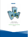
user's manual
nx frequency converters
sliding door application
alfif127
1.
2.
3.
APPLICATION DESCRIPTION.......................................................................................................... 3
NEW PARAMETERS......................................................................................................................... 3
PARAMETER LIST............................................................................................................................ 9
3.1
Monitoring values (Control keypad: menu M1) ...................................................................... 9
3.2
Basic parameters (Control keypad: Menu P2 Æ B2.1) ........................................................ 10
3.3
Input signals (Control keypad: Menu P2 Æ I2.2).................................................................. 12
3.4
Output signals (Control keypad: Menu P2 Æ O2.3).............................................................. 14
3.5
Drive control parameters (Control keypad: Menu P2 Æ D2.4)............................................ 15
3.6
Prohibit frequency parameters (Control keypad: Menu P2 Æ P2.5)................................... 15
3.7
Motor control parameters (Control keypad: Menu P2 Æ M2.6) .......................................... 16
3.8
Protections (Control keypad: Menu P2 Æ P2.7)................................................................... 17
3.9
Autorestart parameters (Control keypad: Menu P2 Æ A2.8) .............................................. 18
3.10 Lift door parameters (Control keypad: Menu P2 Æ L2.9).................................................... 18
3.11 Lift door open parameters (Control keypad: Menu P2 Æ G2.9.2) ....................................... 18
3.12 Lift door close parameters (Control keypad: Menu P2 Æ G2.9.3)....................................... 18
3.13 Keypad control (Control keypad: Menu K3).......................................................................... 19
3.14 System menu (Control keypad: Menu S6) ............................................................................ 19
3.15 Expander boards (Control keypad: Menu E7) ...................................................................... 19
APPLICATION DESCRIPTION
1.
vacon • 3
APPLICATION DESCRIPTION
This special application is based on NXL Multi-Control application. PID and some other small features
are removed. This NXL-application is designed to control the motor, which drives the lift door.
Frequency converter also gives some status information to the lift controller via relay/digital output.
(e.g. torque limit supervision.)
2.
NEW PARAMETERS
L2.9 LIFT DOOR
P2.9.1 Door application
(No/Yes)
G2.9.2 Door opening parameters
P2.9.2.1 Door open acceleration time (0.1 – 3000.0 s)
P2.9.2.2 Door open speed
(0.00 – P2.1.2)
P2.9.2.3 Door open deceleration time
(0.1 – 3000.0s)
P2.9.2.4 Smooth start time (Default=0)
(0.0 – door open acc. time)
P2.9.2.5 Smooth start speed (Default=0)
( 0.00 – door open speed)
P2.9.2.6 Door opening torque limit (0.0 – 150.0 % of motor nominal torque)
P2.9.2.7 Torque superv. delay time (0.0 – 100.0 s)
G2.9.3 Door closing parameters
P2.9.3.1 Door close acceleration time
(0.1 – 3000.0 s)
P2.9.3.2 Door close speed
(0.00 – P2.1.2)
P2.9.3.3 Door close deceleration time
(0.1 – 3000.0 s)
P2.9.3.4 Door closing torque limit
(0.0 – 150.0 % of motor nominal torque)
P2.9.3.5 Torque superv. delay time (0.0 – 100.0 s)
P2.9.4 Emergency deceleration time
P2.9.5 Locking speed mode
P2.9.6 Locking speed control signal
P2.9.7 Locking speed
P2.9.8 Locking speed on-delay time
(0.1 – 3000.0 s)
(0=Only closing, 1=Opening&Closing)
(0=Digital Input, 1=Time Delay)
(0.00 – door close speed)
(0.00 – 300.00s)
24-hour support +358 (0)40 837 1150 • Email: [email protected]
N or m a l seq uency
[frequency]
P. Door open
speed
P. Door open
acc. time
P. Door open
dec. time
P. DC-brake time at stop
P. DC-brake current
O PEN
DIN 1
P. Smooth start
speed
P. Smooth start speed time
[time]
P. Locking speed
P. Door close
speed
P. Door close
acc. time
DIN 1
DIN 2
x DIN 3
Locking speed O N
x DIN 3 does not affect, when opening
P. Door close
dec. time
CLO SE
DIN 2
P2.9.5 " Lock Speed Mode = Only Closing (0)
P2.9.6 " Lock Speed Ctrl. = Digital Input (0)
DIN1
DIN2
DIN Lock.Speed
P2.9.5 " Lock Speed Mode = O pening&Closing (1)
P2.9.6 " Lock Speed Ctrl. = Digital Input (0)
DIN 1
DIN 2
DIN Lock.Speed
tel. +358 (0)201 2121 • Fax +358 (0)201 212 205
P2 .9 .5 " Lock Speed M ode = O pening& Closing (1 )
P2 .9 .6 " Lock Speed Ctrl. = Time Delay (1 )
P2 .9 .8 " Lock Sp. O n-Del, = 3 ,5 s
3 ,5 s
DIN 1
DIN 2
Lock.Speed
3 ,5 s
8 • vacon
NEW PARAMETERS
[frequency]
P. 2.9.2.1 Door open acceleration time
P. 2.9.2.3 Door open deceleration time
Emergency deceleration
OPEN
DIN 1
CLOSE
DIN 2
DIN1
DIN2
[Torque]
P. Door closing
torque limit
P. Torque indication ON - delay (RO)
DO 1
tel. +358 (0)201 2121 • Fax +358 (0)201 212 205
PARAMETER LIST
3.
vacon • 9
PARAMETER LIST
On the next pages you will find the lists of parameters within the respective parameter groups.
Column explanations:
Code
Parameter
Min
Max
Unit
Default
Cust
ID
3.1
=
=
=
=
=
=
=
=
=
Location indication on the keypad; Shows the operator the present param. number
Name of parameter
Minimum value of parameter
Maximum value of parameter
Unit of parameter value; Given if available
Value preset by factory
Customer’s own setting
ID number of the parameter (used with PC tools)
On the parameter code: parameter value can only be changed after the FC has been
stopped.
Monitoring values (Control keypad: menu M1)
The monitoring values are the actual values of parameters and signals as well as statuses and
measurements. Monitoring values cannot be edited.
See Vacon NXL User’s Manual, Chapter 7.3.1 for more information.
Code
V1.1
V1.2
V1.3
V1.4
V1.5
V1.6
V1.7
V1.8
V1.9
V1.10
V1.11
V1.12
V1.13
V1.14
V1.15
V1.16
V1.17
V1.18
V1.19
Parameter
Output frequency
Frequency reference
Motor speed
Motor current
Motor torque
Motor power
Motor voltage
DC-link voltage
Unit temperature
Analogue input 1
Analogue input 2
Analogue output current
Analogue output current 1, expander board
Analogue output current 2, expander board
DIN1, DIN2, DIN3
DIE1, DIE2, DIE3
RO1
ROE1, ROE2, ROE3
DOE 1
Unit
Hz
Hz
rpm
A
%
%
V
V
ºC
V
mA
mA
mA
mA
Table 3-1. Monitoring values
24-hour support +358 (0)40 837 1150 • Email: [email protected]
ID
1
25
2
3
4
5
6
7
8
13
14
26
31
32
15
33
34
35
36
Description
Frequency to the motor
Calculated motor speed
Measured motor current
Calculated actual torque/nominal torque of
the unit
Calculated actual power/nominal power of
the unit
Calculated motor voltage
Measured DC-link voltage
Heat sink temperature
AI1
AI2
AO1
Digital input statuses
I/O expander board: Digital input statuses
Relay output 1 status
I/O exp. board: Relay output statuses
I/O exp. board: Digital output 1 status
10 • vacon
3.2
PARAMETER LIST
Basic parameters (Control keypad: Menu P2 Æ B2.1)
Code
P2.1.1
Parameter
Min frequency
Min
0,00
P2.1.2
Max frequency
Par.
2.1.1
320,00
Hz
50,00
102
P2.1.3
P2.1.4
Acceleration time 1
Deceleration time 1
0,1
0,1
3000,0
3000,0
s
s
1,0
1,0
103
104
P2.1.5
P2.1.6
P2.1.7
Current limit
0,1 x
IL
Nominal voltage of the
180
motor
Nominal frequency of
30,00
the motor
Max
Par. 2.1.2
Unit
Hz
Default
0,00
Cust
ID
101
2,5 x IL
A
1,5 x IL
107
690
V
NXL2:230v
NXL5:400v
110
320,00
Hz
50,00
111
P2.1.8
Nominal speed of the
motor
300
20 000
rpm
1440
112
P2.1.9
Nominal current of
the motor
1 x IL
2,5 x IL
A
IL
113
P2.1.10
Motor cosϕ
0,30
1,00
0,85
120
P2.1.11
Start function
0
1
0
505
P2.1.12
Stop function
0
1
0
506
P2.1.13
U/f optimisation
0
1
0
109
P2.1.14
I/O reference
0
4
0
117
P2.1.15
AI2 signal range
1
4
2
390
0
8
1
307
P2.1.16
Iout content
Note
NOTE: If fmax > than the
motor synchronous speed,
check suitability for motor
and drive system
NOTE: Formulas apply
approximately for
frequency converters up to
MF3. For greater sizes,
consult the factory.
Check the rating plate of
the motor
The default applies for a 4pole motor and a nominal
size frequency converter.
Check the rating plate of
the motor
Check the rating plate of
the motor
0=Ramp
1=Flying start
0=Coasting
1=Ramp
0=Not used
1=Automatic torque boost
0=AI1
1=AI2
2=Keypad reference
3=Fieldbus reference
(FBSpeedReference)
4=Motor potentiometer
Not used if AI2 Custom
min <> 0% or AI2 custom
max. <> 100%
1=0—20 mA
2=4—20 mA
3=0V – 10V
4=2V – 10V
0=Not used
1=Output freq. (0—fmax)
2=Freq. reference (0—fmax)
3=Motor speed (0—Motor
nominal speed)
4=Output current (0—
InMotor)
5=Motor torque (0—TnMotor)
6=Motor power (0—PnMotor)
7=Motor voltage (0—
UnMotor)
8=DC-link volt (0—UnMotor)
tel. +358 (0)201 2121 • Fax +358 (0)201 212 205
PARAMETER LIST
vacon • 11
P2.1.17
DIN2 function
0
8
1
319
P2.1.18
DIN3 function
0
11
11
301
P2.1.19
P2.1.20
Preset speed 1
Preset speed 2
0,00
0,00
Par. 2.1.2
Par. 2.1.2
10,00
50,00
105
106
P2.1.21
Automatic restart
0
1
0
731
P2.1.22
Parameter conceal
0
1
1
115
Hz
Hz
Table 3-2. Basic Parameters
24-hour support +358 (0)40 837 1150 • Email: [email protected]
0=Not used
1=Start Reverse
(DIN1=Start forward)
2=Reverse (DIN1=Start)
3=Stop pulse (DIN1=Start
pulse)
4=External fault, cc
5=External fault, oc
6=Run enable
7=Preset speed 2
8= Motor pot. UP (cc)
0=Not used
1=Reverse
2=External fault, cc
3=External fault, oc
4=Fault reset
5=Run enable
6=Preset speed 1
7=Preset speed 2
8=DC-braking command
9=Motor pot. UP (cc)
10=Motor pot. DOWN (cc)
11=Locking speed
0=Not used
1=Used
0=All parameters and
menus visible
1=Only groups B2.1, M2.6
and L2.9
12 • vacon
3.3
PARAMETER LIST
Input signals (Control keypad: Menu P2 Æ I2.2)
Code
Parameter
Min
Max
P2.2.1
Expander board DIE1
function
0
11
7
368
0
11
4
330
See above
0
11
11
369
See above
0
11
2
499
10
377
3
379
P2.2.2
P2.2.3
P2.2.4
P2.2.5
P2.2.6
P2.2.7
P2.2.8
Expander board DIE2
function
Expander board DIE3
function
DIN4 function (AI1)
AI1 signal
selection
AI1 signal range
AI1 custom minimum
setting
AI1 custom maximum
setting
Unit
0
Default
Cust
ID
0
4
0,00
100,00
%
0,00
380
0,00
100,00
%
100,00
381
0
387
0,10
11
378
388
2
390
P2.2.9
AI1 inversion
0
1
P2.2.10
P2.2.11
AI1 filter time
AI2 signal selection
0,00
0
10,00
P2.2.12
AI2 signal range
1
4
0,00
100,00
%
0,00
391
0,00
100,00
%
100,00
392
0
398
0,10
389
P2.2.13
P2.2.14
AI2 custom minimum
setting
AI2 custom maximum
setting
P2.2.15
AI2 inversion
0
1
P2.2.16
AI2 filter time
0,00
10,00
s
s
Note
0=Not used
1=Reverse
2=External fault, cc
3=External fault, oc
4=Fault reset
5=Run enable
6=Preset speed 1
7=Preset speed 2
8=DC-braking command
9=Motor pot. UP (cc)
10=Motor pot. DOWN
(cc)
11=Locking speed
Used if P2.2.6 = 0
See the selections above
10=AI1 (1=Local, 0=input 1)
11=AI2 (1=Local, 1= input 2)
20=Exp. AI1 (2=exp.board
0=input 1)
21=Exp AI2 (2=exp.board
1=input 2)
0=Digital input 4
1=0mA – 20mA (MF4-->)
2=4mA – 20mA (MF4-->)
3=0V – 10V
4=2V – 10V
Not used if AI2 Custom min
> 0% or AI2 custom max. <
100%
Note! See NXL User’s
manual, chapter 7.3.6: AI1
mode
0=Not inverted
1=Inverted
0=No filtering
As par. 2.2.5
Not used if AI2 Custom min
<> 0% or AI2 custom max. <>
100%
1=0—20 mA
2=4—20 mA
3=0V – 10V
4=2V – 10V
0=Not inverted
1=Inverted
0=No filtering
tel. +358 (0)201 2121 • Fax +358 (0)201 212 205
PARAMETER LIST
P2.2.17
P2.2.18
P2.2.19
Motor potentiometer
frequency reference
memory reset
Reference scaling
minimum value
Reference scaling
maximum value
vacon • 13
0
2
1
367
0,00
P2.2.19
0,00
344
P2.2.1
8
320,00
0,00
345
0=No reset
1=Reset if stopped or
powered down
2=Reset if powered down
P2.2.20
Keypad control
reference selection
0
4
2
121
0=AI1
1=AI2
2=Keypad reference
3=Fieldbus reference
(FBSpeedreference)
4=Motor potentiometer
P2.2.21
Fieldbus control
reference selection
0
4
3
122
See above
Table 3-3. Input signals
24-hour support +358 (0)40 837 1150 • Email: [email protected]
14 • vacon
3.4
PARAMETER LIST
Output signals (Control keypad: Menu P2 Æ O2.3)
Code
P2.3.1
P2.3.2
P2.3.3
P2.3.4
P2.3.5
P2.3.6
P2.3.7
P2.3.8
P2.3.9
P2.3.10
P2.3.11
P2.3.12
Parameter
Relay output 1
function
Exp RO1 function
Exp RO2 function
Exp RO3 function
Exp DO1 function
Analogue output
function
Analogue output
filter time
Analogue output
inversion
Analogue output
minimum
Analogue output
scale
Expander board
analogue output 1
function
Expander board
analogue output 2
function
Min
Max
Unit
Default
Cu
st
ID
Note
0=Not used
1=Ready
2=Run
3=Fault
4=Fault inverted
5=FC overheat warning
6=Ext. fault or warning
7=Ref. fault or warning
8=Warning
9=Reversed
10=Preset speed
11=At speed
12=Mot. regulator active
13=OP freq. limit superv.1
14=Control place: IO
15=Thermistor fault/
warning
16=Actual value supervision
17=Door closing torque
supervision
18=DIN3 status
19= Door opening torque
supervision
As parameter 2.3.1
As parameter 2.3.1
0
19
17
313
0
0
0
0
19
19
19
19
18
0
0
0
314
317
1510
312
0
8
1
307
See par. 2.1.16
0,00
10,00
1,00
308
0=No filtering
0
1
0
309
0
1
0
310
10
1000
100
311
0
8
0
472
As parameter 2.1.16
0
12
0
479
As parameter 2.1.16
0
315
0=No limit
1=Low limit supervision
2=High limit supervision
0,00
316
P2.3.13
Output frequency
limit 1 supervision
0
2
P2.3.14
Output frequency
limit 1;
Supervised value
0,00
Par. 2.1.2
s
%
Hz
As parameter 2.3.1
0=Not inverted
1=Inverted
0=0 mA
1=4 mA
Table 3-4. Output signals
tel. +358 (0)201 2121 • Fax +358 (0)201 212 205
PARAMETER LIST
3.5
vacon • 15
Drive control parameters (Control keypad: Menu P2 Æ D2.4)
Code
Parameter
Min
Max
Unit
Default
P2.4.1
Ramp 1 shape
0,0
10,0
s
0,0
500
P2.4.2
Brake chopper
0
3
0
504
P2.4.3
DC braking current
DC braking time
at stop
Frequency to start
DC braking during
ramp stop
DC braking time
at start
0,15 x In
1,5 x In
A
Varies
507
0,00
600,00
s
0,00
508
0,10
10,00
Hz
1,50
515
0,00
600,00
s
0,00
516
0=DC brake is off at start
P2.4.7
Flux brake
0
1
0
520
0=Off
1=On
P2.4.8
Flux braking current
0,0
Varies
0,0
519
P2.4.4
P2.4.5
P2.4.6
A
Cust
ID
Note
0=Linear
>0=S-curve ramp time
0=Disabled
1=Used in Run state
3=Used in Run and Stop
state
0=DC brake is off at stop
Table 3-5. Drive control parameters
3.6
Prohibit frequency parameters (Control keypad: Menu P2 Æ P2.5)
Code
P2.5.1
P2.5.2
P2.5.3
Parameter
Prohibit frequency
range 1 low limit
Prohibit frequency
range 1 high limit
Prohibit frequencies
acc./dec. ramp
scaling
Min
Max
Unit
Default
0,0
Par. 2.5.2
Hz
0,0
509
0=Not used
0,0
Par. 2.1.2
Hz
0,0
510
0=Not used
518
Multiplier of the currently
selected ramp time
between prohibit
frequency limits
0,1
10,0
Times
1,0
Table 3-6. Prohibit frequency parameters
24-hour support +358 (0)40 837 1150 • Email: [email protected]
Cust
ID
Note
16 • vacon
3.7
PARAMETER LIST
Motor control parameters (Control keypad: Menu P2 Æ M2.6)
Code
Parameter
Min
Max
P2.6.1
Motor control mode
0
1
0
600
P2.6.2
U/f ratio selection
0
3
0
108
30,00
320,00
Hz
50,00
602
10,00
200,00
%
100,00
603
0,00
par.
P2.6.3
Hz
50,00
604
0,00
100,00
%
100,00
605
n% x Unmot
Parameter max. value =
par. 2.6.4
0,00
40,00
%
0,00
606
n% x Unmot
1,0
16,0
kHz
6,0
601
0
1
1
607
0
1
1
608
0
1000
256
1516
Depends on kW
0=Not used
1=Used
0=Not used
1=Used
Measured voltage drop at
stator resistance between
two phases with nom.
Current of motor.
Unit: 256=10 %
P2.6.3
P2.6.4
P2.6.5
P2.6.6
P2.6.7
P2.6.8
P2.6.9
P2.6.10
P2.6.11
Field weakening
point
Voltage at field
weakening point
U/f curve midpoint
frequency
U/f curve midpoint
voltage
Output voltage at
zero frequency
Switching frequency
Overvoltage
controller
Undervoltage
controller
Stator voltage drop
Unit
Default
Cus
t
ID
Note
0=Frequency control
1=Speed control
0=Linear
1=Squared
2=Programmable
3=Linear with flux optim.
n% x Unmot
Table 3-7. Motor control parameters
tel. +358 (0)201 2121 • Fax +358 (0)201 212 205
PARAMETER LIST
3.8
vacon • 17
Protections (Control keypad: Menu P2 Æ P2.7)
Code
Parameter
Min
Max
P2.7.1
Response to 4mA
reference fault
0
3
0
700
0
3
2
701
1
3
2
727
0
3
2
702
0
3
2
703
0
3
2
704
–100,0
100,0
%
0,0
705
0,0
150,0
%
40,0
706
1
200
min
45
707
0
0
100
3
%
100
1
708
709
P2.7.2
P2.7.3
P2.7.4
P2.7.5
P2.7.6
P2.7.7
P2.7.8
P2.7.9
P2.7.10
P2.7.11
Response to
external fault
Response to
undervoltage fault
Output phase
supervision
Earth fault
protection
Thermal
protection of the
motor
Motor ambient
temperature
factor
Motor cooling
factor at zero
speed
Motor thermal
time constant
Motor duty cycle
Stall protection
Unit
Default
Cust
ID
Note
0=No response
1=Warning
2=Fault,stop acc. to 2.1.12
3=Fault,stop by coasting
0=No response
1=Warning
2=Fault,stop acc. to 2.1.12
3=Fault,stop by coasting
As par. 2.7.1
P2.7.12
Stall current limit
0,1
Inmotor x 2
A
P2.7.13
Stall time limit
Stall frequency
limit
Underload
protection
Underload curve at
nominal frequency
Underload curve at
zero frequency
Underload
protection time
limit
Response to
thermistor fault
Response to
fieldbus fault
Response to slot
fault
1,00
120,00
s
Inmotor
x1.3
15,00
1,0
P 2.1.2
Hz
25,0
712
0
3
0
713
10,0
150,0
%
50,0
714
5,0
150,0
%
10,0
715
2,00
600,00
s
20,00
716
0
3
0
732
As par. 2.7.1
0
3
2
733
As par. 2.7.1
0
3
2
734
As par. 2.7.1
0
735
0=No response
1=Warning if below limit
2=Warning if above limit
3=Fault, if below limit
4=Fault, if above limit
P2.7.14
P2.7.15
P2.7.16
P2.7.17
P2.7.18
P2.7.19
P2.7.20
P2.7.21
P2.7.22
P2.7.23
P2.7.24
Actual value
supervision
Actual value
supervision limit
Actual value
supervision delay
710
711
0
4
0,0
100,0
%
10,0
736
0
3600
s
5
737
Table 3-8. Protections
24-hour support +358 (0)40 837 1150 • Email: [email protected]
As par. 2.7.1
18 • vacon
3.9
PARAMETER LIST
Autorestart parameters (Control keypad: Menu P2 Æ A2.8)
Code
P2.8.1
P2.8.2
Parameter
Wait time
Trial time
Min
0,10
0,00
Max
10,00
60,00
P2.8.3
Start function
0
2
Unit
s
s
Default
0,50
30,00
Cust
0
ID
717
718
719
Note
0=Ramp
1=Flying start
2=According to par. 2.4.6
Table 3-9. Autorestart parameters
3.10
Lift door parameters (Control keypad: Menu P2 Æ L2.9)
Code
Parameter
P2.9.1
Door application
Group G2.9.2
Group G2.9.3
Min
0
Max
1
Unit
Default
1
ID
1500
s
1,0
1509
0
1519
P2.9.4
Emergency ramp
0,2
3000,0
P2.9.5
Lock Speed Mode
0
1
1517
P2.9.6
Lock Speed Ctrl
0
1
0
P2.9.7
Locking Speed
0
P2.9.3.2
Hz
5,00
1507
P2.9.8
Lock. Sp. On-Del
0,00
300,00
s
5,00
1518
Note
Activates the door application
Emergency deceleration,
when locking speed is not
active.
0=Locking speed used only
when closing.
1=Locking speed used both in
opening and closing.
Signal selection for the
locking speed control.
0=Digital input
1=Time Delayed (P2.9.8)
Locking speed.
Locking speed on delay, when
parameter P2.9.6 is “1”.
Table 3-10. Lift door parameters
3.11
Lift door open parameters (Control keypad: Menu P2 Æ G2.9.2)
Code
P2.9.2.1
P2.9.2.2
P2.9.2.3
Parameter
Open acc. time
Open speed
Open dec. time
Min
0,1
0,00
0,1
Max
3000,0
P2.1.2
3000,0
Unit
s
Hz
s
Default
1,0
50,00
1,0
ID
1501
1502
1503
P2.9.2.4
Smooth Start Time
0,0
P2.9.2.1
s
0,0
1514
P2.9.2.5
P2.9.2.6
Smooth Start Freq
Torq Lim Open
0,00
0,0
P2.9.2.2
150,0
Hz
%
0,00
50,0
1515
1511
P2.9.2.7
Delay Opening Torq
0,0
100,0
s
1,0
1513
Note
Door open acceleration time
Door open constant frequency
Door open deceleration time
Time for the smooth start
frequency
Smooth start frequency
Torque limit, when opening
Time delay for the opening
torque supervision (=Filtering)
Table 3-11. Lift door open parameters
3.12
Lift door close parameters (Control keypad: Menu P2 Æ G2.9.3)
Code
Parameter
Min
Max
Unit
Default
ID
P2.9.3.1
Close acc. time
0,1
3000,0
s
1,0
1504
Door close acceleration time
Note
P2.9.3.2
P2.9.3.3
P2.9.3.4
Close speed
Close dec. time
Torq Lim Close
0,00
0,1
0,0
P2.1.2
3000,0
150,0
Hz
s
%
50,00
1,0
50,0
1505
1506
1508
P2.9.3.5
Delay closing Torq
0,0
100,0
s
1,0
1512
Door close constant frequency
Door close deceleration time
Torque limit, when closing
Time delay for the closing
torque supervision (=Filtering)
Table 3-12. Lift door close parameters
tel. +358 (0)201 2121 • Fax +358 (0)201 212 205
PARAMETER LIST
vacon • 19
3.13 Keypad control (Control keypad: Menu K3)
The parameters for the selection of control place and direction on the keypad are listed below.
Code
Parameter
Min
Max
P3.1
Control place
1
3
R3.2
Keypad reference
Par.
2.1.1
Par. 2.1.2
P3.3
Direction (on keypad)
0
P3.4
Stop button
0
Unit
Default
Cust
ID
1
125
1
0
123
1
1
114
Note
1 = I/O terminal
2 = Keypad
3 = Fieldbus
Hz
0 = Forward
1 = Reverse
0=Limited function of Stop
button
1=Stop button always
enabled
Table 3-13. Keypad control
3.14 System menu (Control keypad: Menu S6)
For parameters and functions related to the general use of the frequency converter, such as
customised parameter sets or information about the hardware and software, see Chapter 7.3.6 in the
Vacon NXL User’s Manual.
3.15 Expander boards (Control keypad: Menu E7)
The E7 menu shows the expander boards attached to the control board and board-related
information. For more information, see Chapter 7.3.7 in the Vacon NXL User’s Manual.
24-hour support +358 (0)40 837 1150 • Email: [email protected]
Vaasa
Vacon Plc (Head office and production)
Runsorintie 7
65380 Vaasa
[email protected]
telephone: +358 (0)201 2121
fax: +358 (0)201 212 205
Helsinki
Vacon Plc
Äyritie 12
01510 Vantaa
telephone: +358 (0)201 212 600
fax: +358 (0)201 212 699
Vacon Traction Oy
Vehnämyllynkatu 18
33700 Tampere
telephone: +358 (0)201 2121
fax: +358 (0)201 212 710
Tampere
Vacon Plc
Vehnämyllynkatu 18
33700 Tampere
telephone: +358 (0)201 2121
fax: +358 (0)201 212 750
sales companies and representative offices:
Austria
Vacon AT Antriebssysteme GmbH
Aumühlweg 21
2544 Leobersdorf
telephone: +43 2256 651 66
fax: +43 2256 651 66 66
Italy
Vacon S.p.A.
Via F.lli Guerra, 35
42100 Reggio Emilia
telephone: +39 0522 276811
fax: +39 0522 276890
Belgium
Vacon Benelux NV/SA
Interleuvenlaan 62
3001 Heverlee (Leuven)
telephone: +32 (0)16 394 825
fax: +32 (0)16 394 827
The Netherlands
Vacon Benelux BV
Weide 40
4206 CJ Gorinchem
telephone: +31 (0)183 642 970
fax: +31 (0)183 642 971
France
Vacon France s.a.s.
1 Rue Jacquard – BP72
91280 Saint Pierre du Perray CDIS
telephone: +33 (0)1 69 89 60 30
fax: +33 (0)1 69 89 60 40
Norway
Vacon AS
Langgata 2
3080 Holmestrand
telephone: +47 330 96120
fax: +47 330 96130
Germany
Vacon GmbH
Gladbecker Strasse 425
45329 Essen
telephone: +49 (0)201 806 700
fax: +49 (0)201 806 7099
PR China
Vacon Suzhou Drives Co. Ltd.
Blk 11A
428 Xinglong Street
Suchun Industrial Square
Suzhou 215126
telephone: +86 512 6283 6630
fax: +86 512 6283 6618
Great Britain
Vacon Drives (UK) Ltd.
18, Maizefield
Hinckley Fields Industrial Estate
Hinckley
LE10 1YF Leicestershire
telephone: +44 (0)1455 611 515
fax: +44 (0)1455 611 517
Vacon distributor:
Vacon Suzhou Drives Co. Ltd.
Beijing Office
A205, Grand Pacific Garden Mansion
8A Guanhua Road
Beijing 100026
telephone: +86 10 6581 3734
fax: +86 10 6581 3754
Russia
ZAO Vacon Drives
Bolshaja Jakimanka 31,
stroenie 18
109180 Moscow
telephone: +7 (095) 974 14 47
fax: +7 (095) 974 15 54
ZAO Vacon Drives
2ya Sovetskaya 7, office 210A
191036 St. Petersburg
telephone: +7 (812) 332 1114
fax: +7 (812) 279 9053
Singapore
Vacon Plc
Singapore Representative Office
102F Pasir Panjang Road
#02-06 Citilink Warehouse Complex
Singapore 118530
telephone: +65 6278 8533
fax: +65 6278 1066
Spain
Vacon Drives Ibérica S.A.
Miquel Servet, 2. P.I. Bufalvent
08243 Manresa
telephone: +34 93 877 45 06
fax: +34 93 877 00 09
Sweden
Vacon AB
Torget 1
172 67 Sundbyberg
telephone: +46 (0)8 293 055
fax: +46 (0)8 290 755