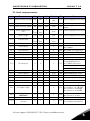
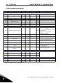
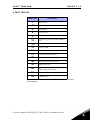
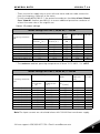
1
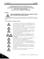
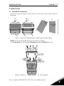
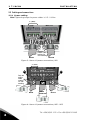
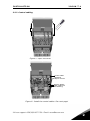
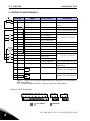
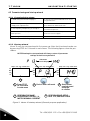
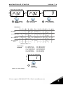
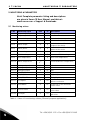
1
• vacon
safety
This quick guide includes the essential steps for easy
installation and setup of your Vacon 10 frequency converter.
Before commissioning your drive, download and read the complete
Vacon 10 User Manual available at:
www.vacon.com -> Support & Downloads
1. SAFETY
ONLY A COMPETENT ELECTRICIAN IS ALLOWED TO CARRY
OUT THE ELECTRICAL INSTALLATION!
This quick guide contains clearly marked warnings which are intended for your personal safety and to avoid any unintentional damage to the product or connected appliances.
Please read these warnings carefully:
The components of the power unit of the frequency converter
are live when Vacon 10 is connected to mains potential. Coming into contact with this voltage is extremely dangerous and
may cause death or severe injury.
The motor terminals U, V, W (T1, T2, T3) and the possible brake
resistor terminals -/+ are live when Vacon 10 is connected to
mains, even if the motor is not running.
The control I/O-terminals are isolated from the mains potential. However, the relay output terminals may have a dangerous control voltage present even when Vacon 10 is
disconnected from mains.
!
The earth leakage current of Vacon 10 frequency converters
exceeds 3.5mA AC. According to standard EN61800-5-1, a
reinforced protective ground connection must be ensured.
See Chapter 7!
If the frequency converter is used as a part of a machine, the
machine manufacturer is responsible for providing the
machine with a main switch (EN 60204-1).
If Vacon 10 is disconnected from mains while running the
motor, it remains live if the motor is energized by the process.
In this case the motor functions as a generator feeding energy
to the frequency converter.
After disconnecting the frequency converter from the mains,
wait until the fan stops and the indicators on the display go
out. Wait 5 more minutes before doing any work on Vacon 10
connections.
The motor can start automatically after a fault situation, if
autorestart function has been activated.
Tel. +358 (0)201 2121 • Fax +358 (0)201 212205
1
installation
vacon
•2
2. INSTALLATION
2.1 Mechanical installation
There are two possible ways to mount Vacon 10 in the wall; either screw or DIN-rail
mounting.
MI1
=M 4
1
MI2-3
2
=M 5
Figure 1: Screw mounting (left) and DIN-rail mounting (right)
NOTE! See the mounting dimensions on the back of the drive.
Leave free space for cooling above (100 mm) and below (50 mm) Vacon 10!
Attach the support
AFTER installing
the power cables
Attach this plate
BEFORE installing
the power cables
Figure 2: Attaching the PE-plate and API cable support
24-hour support +358 (0)40 837 1150 • Email: [email protected]
2
3
• vacon
installation
2.2 Cabling and connections
2.2.1 Power cabling
Note! Tightening torque for power cables is 0.5 - 0.6 Nm
3~ (400V)
1~ (230V)
Motor out
Strip the
plastic cable
coating for
360° earthing
MAINS
MOTOR
Figure 3: Vacon 10 power connections, MI1
3~ (400V)
1~ (230V)
External brake
resistor (400V)
Motor out
L1 L2/N L3 R+ R- U/T1 V/T2 W/T3
Strip the
plastic
cable
coating
for 360°
earthing
MAINS
BRAKE
RESISTOR
MOTOR
Figure 4: Vacon 10 power connections, MI2 - MI3
Tel. +358 (0)201 2121 • Fax +358 (0)201 212205
2
installation
vacon
•4
2.2.2 Control cabling
Figure 5: Open the cover
Control cable
tightening
torque: 0.4 Nm
Strip the plastic
cable coating for
360°earthing
Figure 6: Install the control cables. See next page!
24-hour support +358 (0)40 837 1150 • Email: [email protected]
2
5
• vacon
control i/o
3. CONTROL I/O AND TERMINALS
Terminal
mA
Signal
Factory preset
Description
1
2
+10Vref Ref. voltage out
AI1
Analog signal in 1
Maximum load 10 mA
3
6
GND
24Vout
I/O signal ground
24V output for DI's
7
8
GND
DI1
I/O signal ground
Digital input 1
Start forward P)
9
DI2
Digital input 2
Start reverse P)
10
DI3
Digital input 3
A
B
4
A
B
AI2
RS485 signal A
RS485 signal B
Analog signal in 2
Preset speed B0 P)
FB Communication
FB Communication
5
13
14
GND
GND
DI4
I/O signal ground
I/O signal ground
Digital input 4
Preset speed B1 P)
15
DI5
Digital input 5
Fault reset P)
16
DI6
Digital input 6
Disable PI controlP)
0 - +10 V Ri = 200 k Ω
(min)
Freq. reference P)
± 20 %, max. load 50 mA
0 - +30 V Ri = 12 k Ω min
0(4) - 20 mA, Ri = 200 Ω
PI actual value P)
18
AO
Analog signal out
Output frequency P)
20
DO
Digital signal out
Active = READYP)
22
23
RO 11
RO 12
Relay out 1 Active = RUN P)
24
25
26
RO 21
RO 22
RO 23
Relay out 2 Active = FAULT P)
0 - +30 V Ri = 12 k Ω min
0(4) - 20 mA, RL = 500 Ω
Open collector, max. load
48V/50mA
Max. switching load:
250Vac/2A or 250Vdc/0,4A
Max. switching load:
250Vac/2A or 250Vdc/0,4A
Table 1: Vacon 10 General purpose application default I/O configuration
and connections
P) = Programmable function, see User manual, Parameters
Vacon 10 I/O terminals:
A I2 GND GND DI4 DI5 DI6 AO DO
4
5
1
13
2
3
14
6
16
15
7
8
18
20
9
= API LIMITED
22 23
-
RO2
26
25 24
10
+10V A I1 GND 24V GND DI1 DI2 DI3
+
RO1 RO1
A
B
RO2 RO2
= API RS485
Tel. +358 (0)201 2121 • Fax +358 (0)201 212205
3
navigation & startup
vacon
•6
4. NAVIGATION & STARTUP
4.1 The main menus of Vacon 10
REFERENCE
REF
MENU
Displays the
MON
keypad reference
value
PAR
regardless of
FLT
the selected
control place.
READY R UN STOP ALARM FAULT
READY RUN STOP ALARM FAULT
REF
MON
PAR
PUSH
Hz
FWD
REV
I/O
KEYPAD
Hz
FLT
FWD
BUS
REV
I/O
KEYPAD
BUS
ROTATE
R EADY
MONITORING
MENU
In this menu
you can
browse the
monitoring
values.
RUN STOP ALA RM FAULT
READY
RUN STOP ALARM FAULT
REF
REF
MON
MON
PAR
PA R
PUSH
FLT
FWD
REV
I/O
KEYPAD
FLT
FWD
BUS
REV
I/O
KEYPAD
BUS
ROTATE
READY RUN STOP ALARM FAULT
PARAMETER
MENU
In this menu
you can
browse and
edit the
parameters.
READY RUN STOP ALARM FAULT
REF
REF
MON
MON
PAR
PAR
FLT
PUSH
FWD
REV
I/O
KEYPAD
FLT
BUS
FWD
REV
I/O
KEYPAD
BUS
ROTATE
READY RUN STOP ALARM FAULT
FAULT MENU
Here you will
be able
to browse
through the
faults occurred.
READY RUN STOP ALARM FAU LT
REF
R EF
MON
MON
PAR
PAR
PUSH
FLT
FWD
REV
I/O
KEYPAD
BUS
FLT
FWD
REV
I/O
KEYPAD
BUS
Figure 1: The main menu of Vacon 10
24-hour support +358 (0)40 837 1150 • Email: [email protected]
4
7 • vacon
navigation & startup
4.2 Commissioning and startup wizard
4.2.1 Commissioning steps:
1. Read safety instructions on page 1
6. Run the Startup wizard and set all necessary parameters
2. Secure the grounding and check that cables
comply with requirements
7. Perform test run without motor, see the
User Manual at www.vacon.com
3. Check quality and quantity of cooling air
8. Run no-load tests without motor being connected to the process
4. Check that all start/stop switches are in
STOP position
9. Connect the motor to the process and perform test run once again
5. Connect the drive to mains
10. Vacon 10 is now ready for use
Table 1: Commissioning steps
4.2.2 Startup wizard
Vacon 10 runs the startup wizard in first power-up. After that the wizard can be run
by pressing STOP for 5 seconds in main menu. The following figures show the procedure.
NOTE! Running the startup wizard will always return all parameter
settings to their factory defaults!
Alternates
in the display
READY RUN STOP ALARM FAULT
REF
MON
MON
PA R
PAR
FLT
REF
MON
PAR
rp m
FLT
1
Press STOP
for 5 seconds
in main menu
READY R UN STOP ALARM FAULT
READY RUN STOP ALARM FAULT
REF
2 Push to enter edit mode
THE SAME
4 PERFORM
PROCEDURE FOR PAR. 1.4,
MOTOR NOMINAL CURRENT
FLT
3 Select motor
nominal speed
and push
to confirm.
DRIVE SETUP,
5 PERFORM
PAR. 13.2, SEE NEXT PAGE
Figure 2: Vacon 10 startup wizard (General purpose application)
Tel. +358 (0)201 2121 • Fax +358 (0)201 212205
4
navigation & startup
READY RUN STOP A LARM FAULT
vacon
READY R UN STOP ALARM FAULT
READY RUN STOP ALARM FAULT
REF
REF
REF
MON
MON
MON
PA R
PAR
PAR
FLT
FLT
FLT
1
Startup wizard
shows par 13.2
number.
2
Push to enter
edit mode.
•8
3
Select between
0 - 3, see below!
Selections:
P1.1 P1.2 P1.7 P1.15 P2.1 P2.2 P2.3 P3.1 P3.2 P3.3 P4.2 P4.3
1,1 * 0=
INMOT Not
used
0=
1,1 *
Not
INMOT used
0 = Basic
400
V*
50
Hz
1 = Pump drive
400
V*
50
Hz
2 = Fan drive
400
V*
50
Hz
1,1 *
400
V*
50
Hz
1,5 *
3 = Conveyor
drive
0=
Not
INMOT used
1=
INMOT Used
I/O
0=
0=
0
Ramp Coast. Hz
50
Hz
I/O
1=
0=
20
Ramp Ramp Hz
50
Hz
I/O
0=
0= 20
Ramp Coast. Hz
50
Hz
I/O
0=
0=
0
Ramp Coast. Hz
50
Hz
0=
3s
Ai1
0-10V
0=
5s
Ai1
0-10V
0=
Ai1 20 s
0-10V
0=
1s
Ai1
0-10V
3s
5s
20 s
1s
*In drives of 208V...230V
this value is 230V
Parameters
affected:
P1.1 Motor Un (V)
P1.2 Motor fn (H z)
P1.7 Current limit (A)
P1.15 Torque boost
P2.1 Control place
P2.2 Start function
READY RUN
P2.3 Stop function
P3.1 Min frequency
P3.2 Max frequency
P3.3 I/O reference
P4.2 Acc. time (s)
P4.3 Dec time (s)
STOP ALARM FAULT
REF
MON
PAR
FLT
4
Push to
confirm
drive setup
Figure 3: Drive setup
24-hour support +358 (0)40 837 1150 • Email: [email protected]
4
9
• vacon
monitoring & parameters
5. MONITORING & PARAMETERS
Note! Complete parameter listing and descriptions
are given in Vacon 10 User Manual, available at:
www.vacon.com -> Support & Downloads
5.1 Monitoring values
Code
Monitoring signal
Unit
ID
Description
M1.1
Output frequency
Hz
1
Frequency to the motor
M1.2
Frequency reference
Hz
25
M1.3
Motor shaft speed
rpm
2
Calculated motor speed
M1.4
Motor current
A
3
Measured motor current
M1.5
Motor torque
%
4
Calculated actual/nominal
torque of the motor
M1.6
Motor power
%
5
Calculated actual/nominal
power of the motor
M1.7
Motor voltage
V
6
Motor voltage
M1.8
DC-link voltage
V
7
Measured DC-link voltage
M1.9
Unit temperature
C
°
8
Heat sink temperature
C
°
M1.10
Motor temperature
M1.11
Analogue input 1
%
13
AI1 value
Calculated motor temperature
M1.12
Analogue input 2
%
14
AI2 value
M1.13
Analogue output
%
26
AO1
M1.14
DI1, DI2, DI3
15
Digital input statuses
M1.15
DI4, DI5, DI6
16
Digital input statuses
M1.16
RO1, RO2, DO
17
Relay/digital output statuses
M1.17
PI setpoint
%
20
In percent of the maximum
process reference
M1.18
PI feedback
%
21
In percent of the maximum
actual value
M1.19
PI error value
%
22
In percent of the maximum
error value
M1.20
PI Output
%
23
In percent of the maximum output value
Table 1: Vacon 10 monitoring values (General purpose application)
Tel. +358 (0)201 2121 • Fax +358 (0)201 212205
5
monitoring & parameters
vacon
• 10
5.2 Quick setup parameters
Code
Parameter
Min
Max
Unit
Default
ID
Note
P1.1
Motor nominal voltage
180
500
V
230
400
110
Check rating plate on the motor
P1.2
Motor nom. frequency
30
320
Hz
50,00
111
Check rating plate on the motor
P1.3
Motor nominal speed
300
20000
rpm
1440
112
Default applies for a 4-pole
motor.
P1.4
Motor nominal current
0,2 x
INunit
1,5 x
INunit
A
INunit
113
Check rating plate on the motor
ϕ
0,30
1,00
0,85
120
Check rating plate on the motor
2x
INunit
A
1,5 x
INunit
107
P1.5
Motor cos
P1.7
Current limit
0,2 x
INunit
P1.15
Torque boost
0
1
0
109
0 = Not used 1 = Used
P2.1
Control place
1
3
1
125
1 = I/O terminal 2 = Keypad
3 = Fieldbus
P2.2
Start function
0
1
0
505
0 = Ramp 1 = Flying start
P2.3
Stop function
0
1
0
506
0 = Coasting 1 = Ramp
P3.1
Min frequency
0,00
P3.2
Hz
0,00
101
P3.2
Max frequency
P3.1
320
Hz
50,00
102
P3.3
I/O reference
0
4
3
117
0 = Preset Speeds (0-7)
1 = Keypad Reference
2 = Fieldbus Reference
3 = AI1 (API LIMITED & FULL)
4 = AI2 (API FULL)
P3.4
Preset speed 0
0,00
P3.2
Hz
5,00
124
Activated by digital inputs
P3.5
Preset speed 1
0,00
P3.2
Hz
10,00
105
Activated by digital inputs
P3.6
Preset speed 2
0,00
P3.2
Hz
15,00
106
Activated by digital inputs
P3.7
Preset speed 3
0,00
P3.2
Hz
20,00
126
Activated by digital inputs
P4.2
Acceleration time
0,1
3000
s
1,0
103
P4.3
Deceleration time
0,1
3000
s
1,0
104
P6.1
AI1 Signal range
0
3
0
379
0 = Voltage 0…10 V (F + L)
1 = Voltage 2…10 V (F + L)
2 = Current 0…20 mA (L)
3 = Current 4…20 mA (L)
P6.5
AI2 Signal range
(API FULL)
2
3
3
390
2 = Current 0…20 mA
3 = Current 4…20 mA
P10.4
Automatic restart
0
1
0
731
0 = Not used 1 = Used
P13.1
Parameter
conceal
0
1
1
115
0 = All parameters visible
1 = Only basic parameters
Table 2: Quick setup parameters (General purpose application)
24-hour support +358 (0)40 837 1150 • Email: [email protected]
5
11
• vacon
monitoring & parameters
5.3 System menu parameters
Code
Parameter
Min
Max
Default
ID
Note
Software information (MENU PAR -> S1)
S1.1
Software package
833
S1.2
Power SW version
834
S1.3
API SW version
835
S1.4
API Firmware interface
836
S1.5
Application ID
837
S1.6
Application revision
838
S1.7
System load
839
RS485 information (MENU PAR -> S2)
S2.1
Communication status
0
808
Format: xx.yyy
xx = 0 - 64 (Number of error
messages)
yyy = 0 - 999 (Number of
good messages)
809
0 = FB disabled 1= Modbus
S2.2
Fieldbus protocol
0
1
S2.3
Slave address
1
255
S2.4
Baud rate
0
5
5
811
810
0=300, 1=600, 2=1200,
3=2400, 4=4800, 5=9600,
S2.5
Number of stop bits
0
1
1
812
0=1, 1=2
S2.6
Parity type
0
0
0
813
0= None (locked)
S2.7
Communication timeout
0
255
0
814
0= Not used, 1= 1 second, 2=
2 seconds, etc.
S2.8
Reset communication
status
815
1= Resets par. S2.1
Total counters (MENU PAR -> S3)
S3.1
MWh counter
0
1
0
S3.2
Power on days
0
1
0
827
828
S3.3
Power on hours
0
1
0
829
S4.1
Display contrast
0
15
7
830
Adjusts the display contrast
S4.2
Restore factory defaults
0
1
0
831
1= Restores factory defaults
User settings (MENU PAR -> S4)
Table 3: System menu parameters
Tel. +358 (0)201 2121 • Fax +358 (0)201 212205
5
fault tracing
vacon
• 12
6. FAULT TRACING
Fault code
Fault name
1
Overcurrent
2
Overvoltage
3
Earth fault
8
System fault
9
Undervoltage
13
Frequency converter undertemperature
14
Frequency converter overtemperature
15
Motor stalled
16
Motor overtemperature
22
EEPROM checksum fault
25
Microcontroller watchdog fault
34
Internal bus communication
35
Application fault
50
Analogue input Iin < 4mA (selected
signal range 4 to 20 mA)
51
External fault
53
Fieldbus fault
Table 1: Fault codes. See User Manual for detailed fault
descriptions.
24-hour support +358 (0)40 837 1150 • Email: [email protected]
6
• vacon
13
general data
7. GENERAL DATA
Dimensions
and weight
Frame
Height Width Depth (mm) Weight (kg)
MI1
156,5
65,5
98,5
0,55
MI2
195
90
101,5
0,70
262,5
100
108,5
0,99
MI3
Supply network Networks
Vacon 10 cannot be used with corner grounded networks
Short circuit current
Maximum short circuit current has to be < 50kA
Motor
connection
Output voltage
0 - Uin
Output current
Continuous rated current IN at ambient temperature max. +50ºC, overload 1.5 x IN max. 1min/10min
Ambient
conditions
Ambient operating
temperature
-10°C (no frost)…+50°C: rated loadability IN
Storage temperature
-40°C…+70°C
Enclosure class
IP20
EMC
Relative humidity
0…95% RH, non-condensing, non-corrosive, no dripping water
Altitude
100% load capacity (no derating) up to 1000m. 1% derating for each
100m above 1000m; max. 2000m
Immunity
Complies with EN50082-1, -2, EN61800-3
Emissions
230V : Complies with EMC category C2 (Vacon level H); With an internal
RFI filter
400V: Complies with EMC category C2 (Vacon level H): With an internal
RFI filter
Both: No EMC emission protection (Vacon level N): Without RFI filter
See detailed descriptions in Vacon 10 User Manual at:
www.vacon.com/support
For EMC: EN61800-3,
For safety: UL508C, EN61800-5-1
Standards
Certificates
and manufacturer’s declarations of
conformity
Cable and fuse requirements
380 - 500V
208 - 240V
For safety: CB, CE, UL, cUL,
For EMC: CE, CB, c-tick
(see unit nameplate for more detailed approvals)
Frame
Fuse
(A)
MI1
6
MI2
10
Mains cable
Cu (mm2)
3*1.5+1.5
MI3
20
3*2.5+2.5
MI1
10
2*1.5+1.5
MI2
20
2*2.5+2.5
MI3
32
2*6+6
Terminal cable min-max (mm2)
Main & earth
Control & relay
1.5-4
1.5-6
0.5-1.5
1.5-4
1.5-6
- With above-mentioned fuses, the drive can be connected to power supply the short
circuit current of which is max. 50kA
- Use cables with heat resistance of at least +70 C.
- The fuses function also as cable overload protection.
Tel. +358 (0)201 2121 • Fax +358 (0)201 212205
7
general data
vacon
• 14
- These instructions apply only to cases with one motor and one cable connection
from the frequency converter to the motor.
- To fulfil standard EN61800-5-1, the protective conductor should be at least 10mm2
Cu or 16mm Al. Another possibility is to use an additional protective conductor of
at least the same size as the original one.
Vacon 10 power ratings
Mains voltage 208-240 V, 50/60 Hz, 1~ series
Rated loadability
Frecuency converter
type
Vacon 10-1L-0001 - 2
Vacon 10-1L-0002 - 2
Vacon 10-1L-0003 - 2
Vacon 10-1L-0004 - 2
Vacon 10-1L-0005 - 2
Vacon 10-1L-0007 - 2
Vacon 10-1L-0009 - 2 *
100% contin.
current IN [ A ]
1,7
2,4
2,8
3,7
4,8
7,0
9,6
150% overload
current [ A ]
Motor
shaft
power
P
[ kW ]
2,6
3,6
4,2
5,6
7,2
10,5
14,4
0,25
0,37
0,55
0,75
1,1
1,5
2,2
Nominal
Mechaniinput current cal size
[A]
4,2
5,7
6,6
8,3
11,2
14,1
15,8
MI1
MI1
MI1
MI1
MI2
MI2
MI3
* The maximum ambient operating temperature of Vacon 10-1L-0009 - 2 is +40°C!
Mains voltage 380-480 V, 50/60 Hz, 3~ series
Rated loadability
Frecuency converter
type
Vacon 10-3L-0001 - 4
Vacon 10-3L-0002 - 4
Vacon 10-3L-0003 - 4
Vacon 10-3L-0004 - 4
Vacon 10-3L-0005 - 4
Vacon 10-3L-0006 - 4
Vacon 10-3L-0008 - 4
Vacon 10-3L-0009 - 4
Vacon 10-3L-0012 - 4
100% continuous current
IN [ A ]
1,3
1,9
2,4
3,3
4,3
5,6
7,6
9,0
12,0
Motor shaft
power
150% overload current
[A]
2,0
2,9
3,6
5,0
6,5
8,4
11,4
13,5
18,0
380-480V supply
P[ kW ]
0,37
0,55
0,75
1,1
1,5
2,2
3,0
4,0
5,5
Nominal
input current
[A]
2,2
2,8
3,2
4,0
5,6
7,3
9,6
11,5
14,9
Mechani
cal size
MI1
MI1
MI1
MI1
MI2
MI2
MI3
MI3
MI3
Note: The input currents are calculated values with 100 kVA line transformer supply.
24-hour support +358 (0)40 837 1150 • Email: [email protected]
7
head office and
production:
Vaasa
Vacon Plc
Runsorintie 7
65380 Vaasa
[email protected]
telephone: +358 (0)201 2121
fax: +358 (0)201 212 205
production:
production:
Suzhou, China
Vacon Suzhou Drives Co. Ltd.
Building 11A
428# Xinglong Street, SIP
Suchun Industrial Square
Suzhou 215126
telephone: + 86 512 62836630
fax: + 86 512 62836618
Chambersburg, USA
3181 Black Gap Road
Chambersburg, PA 17202
Naturno, Italy
Vacon S.R.I
Via Zone Industriale, 11
39025 Naturno
TB Wood's (India) Pvt. Ltd.
#27, 'E' Electronics City
Hosur Road
Bangalore - 560 100
India
Tel. +91-80-30280123
Fax. +91-80-30280124
sales companies and representative offices:
finland
Helsinki
Vacon Plc
Äyritie 8
01510 Vantaa
telephone: +358 (0)201 212 600
fax: +358 (0)201 212 699
Tampere
Vacon Plc
Vehnämyllynkatu 18
33580 Tampere
telephone: +358 (0)201 2121
fax: +358 (0)201 212 750
australia
Vacon Pacific Pty Ltd
5/66-74, Micro Circuit
Dandenong South, VIC 3175
telephone: +61 (0)3 9238 9300
fax: +61 (0)3 92389310
austria
Vacon AT Antriebssysteme GmbH
Aumühlweg 21
2544 Leobersdorf
telephone: +43 2256 651 66
fax: +43 2256 651 66 66
belgium
Vacon Benelux NV/SA
Interleuvenlaan 62
3001 Heverlee (Leuven)
telephone: +32 (0)16 394 825
fax: +32 (0)16 394 827
brazil
Vacon Brazil
Alameda Mamoré, 535
Alphaville - Barueri -SP
Tel. +55 11 4166-5707
Fax. +55 11 4166-5567
canada
Vacon Canada
221 Griffith Road
Stratford, Ontario N5A 6T3
telephone: +1 (519) 508-2323
fax: +1 (519) 508-2324
china
Vacon Suzhou Drives Co. Ltd.
Beijing Branch
A528, Grand Pacific Garden Mansion
8A Guanghua Road
Beijing 100026
telephone: + 86 10 51280006
fax: +86 10 65813733
czech republic
Vacon s.r.o.
Kodanska 1441/46
110 00 Prague 10
telephone: +420 234 063 250
fax: +420 234 063 251
france
Vacon France
ZAC du Fresne
1 Rue Jacquard - BP72
91280 Saint Pierre du Perray CDIS
telephone: +33 (0)1 69 89 60 30
fax: +33 (0)1 69 89 60 40
germany
Vacon GmbH
Gladbecker Strasse 425
45329 Essen
telephone: +49 (0)201 806 700
fax: +49 (0)201 806 7099
slovakia
Vacon s.r.o. (Branch)
Seberiniho 1
821 03 Bratislava
Tel. +421 243 330 202
Fax. +421 243 634 389
Vacon OEM Business Center GmbH
Industriestr. 13
51709 - Marienheide
Germany
Tel. +49 02264 17-17
Fax. +49 02264 17-126
spain
Vacon Drives Ibérica S.A.
Miquel Servet, 2. P.I. Bufalvent
08243 Manresa
telephone: +34 93 877 45 06
fax: +34 93 877 00 09
india
Vacon Drives & Control Plc
Plot No 352
Kapaleeshwar Nagar
East Coast Road
Neelangarai
Chennai-600041
Tel. +91 44 244 900 24/25
sweden
Vacon AB
Anderstorpsvägen 16
171 54 Solna
telephone: +46 (0)8 293 055
fax: +46 (0)8 290 755
italy
Vacon S.p.A.
Via F.lli Guerra, 35
42100 Reggio Emilia
telephone: +39 0522 276811
fax: +39 0522 276890
the netherlands
Vacon Benelux BV
Weide 40
4206 CJ Gorinchem
telephone: +31 (0)183 642 970
fax: +31 (0)183 642 971
norway
Vacon AS
Bentsrudveien 17
3080 Holmestrand
telephone: +47 330 96120
fax: +47 330 96130
romania
Vacon Romania - Reprezentanta
Cuza Voda 1
400107 Cluj Napoca
Tel. +40 364 118 981
Fax. +40 364 118 981
russia
ZAO Vacon Drives
Ul. Letchika Babushkina 1,
Stroenie 3
129344 Moscow
telephone: +7 (495) 363 19 85
fax: +7 (495) 363 19 86
ZAO Vacon Drives
2ya Sovetskaya 7, office 210A
191036 St. Petersburg
telephone: +7 (812) 332 1114
fax: +7 (812) 279 9053
thailand
Vacon South East Asia
335/32 5th-6th floor
Srinakarin Road, Prawet
Bangkok 10250
Tel. +66 (0)2366 0768
ukraine
Vacon Drives Ukraine (Branch)
42-44 Shovkovychna Str.
Regus City Horizon Tower
Kiev 01601, Ukraine
Tel. +380 44 459 0579
Fax +380 44 490 1200
united arab emirates
Vacon Middle East and Africa
Block A, Office 4A 226
P.O.Box 54763
Dubai Airport Free Zone
Dubai
Tel. +971 (0)4 204 5200
Fax: +971 (0)4 204 5203
united kingdom
Vacon Drives (UK) Ltd.
18, Maizefield
Hinckley Fields Industrial Estate
Hinckley
LE10 1YF Leicestershire
telephone: +44 (0)1455 611 515
fax: +44 (0)1455 611 517
united states
Vacon, Inc.
3181, Black Gap Road
Chambersburg, PA 17202
telephone: +1 (877) 822-6606
fax: +1 (717) 267-0140