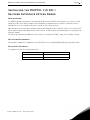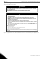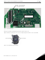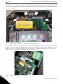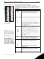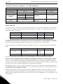
1
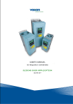
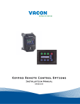
X5OPT01 115 VAC Encoder Interface
Option Board
Installation Manual
DPD00113
Need Help?
This manual answers most installation and startup questions
that may arise. However, if you have any problems,
please let your first call be to us.
Vacon, Inc.
Chambersburg, PA 17202
Normal business hours:
(North America)
8:00 AM to 5:00 PM, Eastern time
+1 877-Vacon06
(+1 877-822-6606)
After-hours support is also available
and Vacon, Inc. are trademarks of Vacon Plc, a member of Vacon Group.
All other product names are trademarks of their respective companies.
Copyright 2009, Vacon, Incorporated. All rights reserved.
X5OPT01 115 VAC / Encoder Interface Option Board
vacon
3
Installing the X5OPT01 115 VAC /
Encoder Interface Option Board
Introduction
The X5OPT01 provides the option of controlling X5 AC drives from 115 VAC control signals, or to connect a shaftmounted encoder to the drive to improve speed regulation. A maximum of five channels of 115 VAC control is
available for use in selecting direction, preset speeds, or other drive functions.
With this option, an encoder with a nominal rating of up to 2048 pulses per revolution can be connected to the X5
unit to improve speed load regulation of the drive. Overall encoder frequency at maximum process speed must be
limited to 100kHz.
This option also provides two additional control relays, each rated for 115 VAC, 1 amp, or for 230 VAC, 0.5 amp.
Applicable Documents
This manual is supplied as a supplement to the X5 AC Drive User’s Manual (DPD 00089, previously Form 1434).
Option Kit Contents
The option kit includes the following materials:
Part Number
Description
25100079C
115 VAC / Encoder Option Board
32100391
Flexible cable assembly
Email: [email protected] • Fax 717-264-3115
4
X5OPT01 115 VAC / Encoder Interface Option Board
vacon
Installation Procedures
!
WARNING
SENSITIVE EQUIPMENT
This assembly contains static-sensitive components. It should be handled only by a static-safe installer,
using a grounded wrist strap.
Failure to observe this precaution may cause premature equipment failure.
!
DANGER
HAZARDOUS VOLTAGE
• Disconnect all power before servicing a drive unit or its components. WAIT 5 MINUTES until the DC
bus capacitors discharge.
• Ensure that any other power sources that may feed control logic have been disconnected.
• DO NOT short across DC bus capacitors or touch unshielded components or terminal strip screw
connections with voltage present.
• Install all covers before applying power or starting and stopping the drive.
• The user is responsible for conforming to all applicable code requirements with respect to grounding
all equipment.
• Many parts in a drive, including printed circuit boards, operate at line voltage. DO NOT TOUCH. Use
only electrically-insulated tools.
Before servicing any drive.
• Disconnect all power.
• Place a “DO NOT TURN ON” label on the drive disconnect.
• Lock the disconnect in the open position.
Failure to observe these precautions will cause shock or burn, resulting in severe personal injury
or death.
Figure 1 on page 5 illustrates the option board and the location of the terminals and the power supply selector.
24-hour support 1-877-822-6606
X5OPT01 115 VAC / Encoder Interface Option Board
vacon
Encoder / 115 VAC Interface
Control Relay Terminals
Encoder Interface Power
Supply Selector
Figure 1: Option Board Layout
Before you can install the option board, you must first remove the drive cover.
Figure 2 shows the locations of the cover screws. The torque range for the X5 Size 1 cover is 18-26 in/lbs.
Cover screw locations
Figure 2: Cover Assembly and Screw Locations
Email: [email protected] • Fax 717-264-3115
Cover screw locations
5
6
X5OPT01 115 VAC / Encoder Interface Option Board
vacon
The option board is installed just above the control board in all configurations (a Size 1 unit is shown in Figure 3 for
reference). The screws labeled “A” must be removed from the drive unit; those labeled “B” need only to be loosened
to accept the board slot.
.
B
B
A
A
Figure 3: Option Mounting Locations
Once the board is in place, tighten the screws to a maximum of 26 in-lbs.
Next, install the flexible circuit to finish the interface to the control board. (Refer to Figure 4 on page 6.) To install the
flexible circuit, first remove the keypad frame (necessary in this size unit). The frame is attached with two screws in
opposite corners; the screws thread into fasteners in the plastic assembly. After the flexible circuit is installed,
replace these screws, limiting the installation torque to 12 in-lbs..
Figure 4: Flexible Circuit Interface to Control Board
24-hour support 1-877-822-6606
X5OPT01 115 VAC / Encoder Interface Option Board
vacon
7
115 VAC Interface / Relay / Encoder Interface Terminals
The X5OPT01 option kit includes five 115 VAC inputs, two additional
programmable relays, and an encoder interface. The details of the terminals on
the board related to the 115 VAC interface and the encoder are shown in the
following table:
Terminal
Figure 5: 115 VAC Interface /
Encoder Terminals
Note that the connections
described in Table 1 work only
when the encoder has an internal
pull-up resistor on the open collector. Alternatively, it might be
preferable to pull the + channel
high, and attach the open collector to the - channel. For example,
if using Channel A, A+ on the
option board would be tied to
VDC, and A- would be connected
to the open collector coming
from the encoder. The advantage
in this method is that no pull-up/
down resistors are needed; if the
encoder has an internal pull-up,
this does not affect anything.
DI-A
DI-B
DI-C
DI-D
DI-E
115 VAC logic input; connect input to 115 VAC to activate.
The programmable functionality of these inputs is controlled
by parameters 728, 729, 730, 731, and 732. Each of these
inputs can be disabled or configured to emulate the function
of the FWD, REV, R/J, EN, MOL, DI1, DI2, DI3, DI4, or DI5 input
terminals on the X5 control board.
Refer to the X5 User’s Manual for more information.
ACn
The neutral connection for the 115 VAC control inputs
NO3
RC3
NC3
The third auxiliary relay.
The function of this relay is set by parameter 709.
Functionally, it is capable of each of the features outlined in
the X5 User’s Manual under parameters 705-708.
Terminal NO3 is a normally-open contact; it will close when
the relay activates. NC3 is a normally-closed contact; it will
open when the relay activates. RC3 is the common terminal
associated with both contacts.
The ratings of these contacts are 115 VAC, 1 amp; and 230
VAC, 0.5 amp.
NO4
RC4
NC4
The fourth auxiliary relay.
The function of this relay is set by parameter 710.
Functionally, it is capable of each of the features outlined in
the X5 User’s Manual under parameters 705-708.
Terminal NO4 is a normally-open contact; it will close when
the relay activates. NC4 is a normally-closed contact; it will
open when the relay activates. RC4 is the common terminal
associated with both contacts.
The ratings of these contacts are 115 VAC, 1 amp; and 230
VAC, 0.5 amp.
A+
A-
Channel A input from the encoder. Compatible with line
driver, open collector, or totem pole outputs from an
encoder. If it is an open collector or totem pole-type, encoder
outputs are used; connect the A- terminal to Ecom.
B+
B-
Channel B input from the encoder. Compatible with line
driver, open collector, or totem pole outputs from an
encoder. If it is an open collector or totem pole-type, encoder
outputs are used; connect the B- terminal to Ecom.
C+
C-
Channel C input from the encoder, the home pulse.
Compatible with line driver, open collector, or totem pole
outputs from an encoder. If it is an open collector or totem
pole-type, encoder outputs are used; connect the Cterminal to Ecom.
VDC
Ecom
Email: [email protected] • Fax 717-264-3115
Description
Power supply terminal for use with a customer-supplied
encoder. It can be either +12 VDC or +5 VDC based on the
position of the encoder interface power supply selector
shown in Figure 1. Voltage regulation: +/- 5%; maximum
current available is 100 mA.
Signal common for the encoder interface
8
X5OPT01 115 VAC / Encoder Interface Option Board
vacon
Specifications for Encoder / 115 VAC Interface
Encoder Interface
Speed regulation
115 VAC Interface
< 0.1 Hz (1)
On state
Input frequency (max.)
100 kHz
Off state
< 10 VAC
Input voltage
10-24 VDC +/- 5%
Input frequency
58-62 Hz
Suggested pull-up
resistor
Terminal block wire
limitations
5 VDC
500 ohms
12 VDC
1k ohms
24 VDC
3.3k ohms
12-24 AWG
90-140 VAC
On/off delay
30 ms maximum
Terminal block wire
limitations
12-24 AWG
(1) PID feedback plus optimal motor turning in SLV mode employed
Setup and Use
The encoder interface is most effective if used in conjunction with the vector mode of operation. Refer to Chapter 6
of the X5 User’s Manual for detailed information about using the vector mode. Three additional parameters are
provided to calibrate the encoder:
Parameter #
Parameter Name
Range
Default Value
219
Encoder Pulses per Revolution
0-16383
1024
220
Encoder Filter Time
10-1000 ms
20 ms
221
Encoder Speed Protection
0-20.0%
0%
Parameter 219, Encoder Pulses per Revolution, can either be extracted from the encoder nameplate or the data
sheet supplied with it. Parameter 220, Encoder Filter Time, is used to filter the encoder signal in the event of noise.
Parameter 221 is for limiting the response of the drive, in the event of the loss of encoder signal.
Two other parameters are provided to allow more flexibility in encoder selection, and to improve PID application
usage:
Parameter #
Parameter Name
Range
Default Value
EncoderType
Quadrature
or Single
Channel
Quadrature
223
224
Encoder Range
0-24000 rpm
0 rpm
Parameter 223, Encoder Type, allows the use of either quadrature or single-channel types of encoders.
Parameter 224, Encoder Range, improves PID application flexibility. This parameter should be used in situations
where the encoder feedback signal is not always directly proportional to the motor speed, for example, a winder
using an encoder mounted on an idler pulley feeding a winding spool. The PID may be attempting to maintain a
constant linear speed on the wound media, but as the diameter of the media on the spool changes, the motor turning
the spool needs to vary its speed to maintain the linear speed at the idler pulley.
When parameter 224 is set to 0, it is ignored, and the PID calculates the feedback percentage based on parameter
301, Maximum Frequency. When this parameter is set to a non-zero value, the PID uses instead Parameter 224’s
setting to calculate the feedback percentage.
Encoder feedback works similarly to an analog input as configured in parameters 850 (PID Configure), 851 (PID
Feedback), 852 (PID Prop Gain), 853 (PID Int Gain), and 859 (PID Derivative Gain). The “feed forward” options are
suggested for setting parameter 850. More specific details on each of the listed parameters can be found in the X5
User’s Manual.
24-hour support 1-877-822-6606
X5OPT01 115 VAC / Encoder Interface Option Board
vacon
9
The encoder interface can easily serve as one of the inputs to the X5’s Keeper Function (data logging). More
information on this feature is in the X5 User’s Manual.
Both the Vmet and Imet output from the drive can be configured to indicate the status of the encoder. Parameters
700 (Vmet) and 702 (Imet) that relate to the setup and calibration of the Vmet and Imet outputs, both have selections
related to the status of the encoder input.
The Program Sequencer function can also key off the encoder’s home pulse. To make use of this function, the
encoder’s home pulse (1 pulse per revolution) must be connected to the C- input of the encoder board.
Troubleshooting
Any problem with the encoder interface will result in an F37 fault. Four advanced fault codes are available to help
you determine whether you have an encoder calibration problem, or a defect. For more information on
troubleshooting, refer to the Troubleshooting chapter in the X5 User’s Manual.
Email: [email protected] • Fax 717-264-3115
head office and production:
Vaasa
Vacon Plc
Runsorintie 7
65380 Vaasa
[email protected]
telephone: +358 (0)201 2121
fax: +358 (0)201 212 205
production:
Suzhou, China
Vacon Suzhou Drives Co. Ltd.
Building 11A
428# Xinglong Street, SIP
Suchun Industrial Square
Suzhou 215126
telephone: + 86 512 62836630
fax: + 86 512 62836618
Naturno, Italy
Vacon S.R.I
Via Zone Industriale, 11
39025 Naturno
production:
Chambersburg, USA
3181 Black Gap Road
Chambersburg, PA 17202
TB Wood's (India) Pvt. Ltd.
#27, 'E' Electronics City
Hosur Road
Bangalore - 560 100
India
Tel. +91-80-30280123
Fax. +91-80-30280124
sales companies and representative offices:
finland
Helsinki
Vacon Plc
Äyritie 8
01510 Vantaa
telephone: +358 (0)201 212 600
fax: +358 (0)201 212 699
Tampere
Vacon Plc
Vehnämyllynkatu 18
33580 Tampere
telephone: +358 (0)201 2121
fax: +358 (0)201 212 750
australia
Vacon Pacific Pty Ltd
5/66-74, Micro Circuit
Dandenong South, VIC 3175
telephone: +61 (0)3 9238 9300
fax: +61 (0)3 92389310
austria
Vacon AT Antriebssysteme GmbH
Aumühlweg 21
2544 Leobersdorf
telephone: +43 2256 651 66
fax: +43 2256 651 66 66
belgium
Vacon Benelux NV/SA
Interleuvenlaan 62
3001 Heverlee (Leuven)
telephone: +32 (0)16 394 825
fax: +32 (0)16 394 827
brazil
Vacon Brazil
Alameda Mamoré, 535
Alphaville - Barueri -SP
Tel. +55 11 4166-5707
Fax. +55 11 4166-5567
canada
Vacon Canada
221 Griffith Road
Stratford, Ontario N5A 6T3
telephone: +1 (519) 508-2323
fax: +1 (519) 508-2324
china
Vacon Suzhou Drives Co. Ltd.
Beijing Branch
A528, Grand Pacific Garden Mansion
8A Guanghua Road
Beijing 100026
telephone: + 86 10 51280006
fax: +86 10 65813733
czech republic
Vacon s.r.o.
Kodanska 1441/46
110 00 Prague 10
telephone: +420 234 063 250
fax: +420 234 063 251
france
Vacon France
ZAC du Fresne
1 Rue Jacquard - BP72
91280 Saint Pierre du Perray CDIS
telephone: +33 (0)1 69 89 60 30
fax: +33 (0)1 69 89 60 40
germany
Vacon GmbH
Gladbecker Strasse 425
45329 Essen
telephone: +49 (0)201 806 700
fax: +49 (0)201 806 7099
slovakia
Vacon s.r.o. (Branch)
Seberiniho 1
821 03 Bratislava
Tel. +421 243 330 202
Fax. +421 243 634 389
Vacon OEM Business Center GmbH
Industriestr. 13
51709 - Marienheide
Germany
Tel. +49 02264 17-17
Fax. +49 02264 17-126
spain
Vacon Drives Ibérica S.A.
Miquel Servet, 2. P.I. Bufalvent
08243 Manresa
telephone: +34 93 877 45 06
fax: +34 93 877 00 09
india
Vacon Drives & Control Plc
Plot No 352
Kapaleeshwar Nagar
East Coast Road
Neelangarai
Chennai-600041
Tel. +91 44 244 900 24/25
sweden
Vacon AB
Anderstorpsvägen 16
171 54 Solna
telephone: +46 (0)8 293 055
fax: +46 (0)8 290 755
italy
Vacon S.p.A.
Via F.lli Guerra, 35
42100 Reggio Emilia
telephone: +39 0522 276811
fax: +39 0522 276890
the netherlands
Vacon Benelux BV
Weide 40
4206 CJ Gorinchem
telephone: +31 (0)183 642 970
fax: +31 (0)183 642 971
norway
Vacon AS
Bentsrudveien 17
3080 Holmestrand
telephone: +47 330 96120
fax: +47 330 96130
romania
Vacon Romania - Reprezentanta
Cuza Voda 1
400107 Cluj Napoca
Tel. +40 364 118 981
Fax. +40 364 118 981
russia
ZAO Vacon Drives
Ul. Letchika Babushkina 1,
Stroenie 3
129344 Moscow
telephone: +7 (495) 363 19 85
fax: +7 (495) 363 19 86
ZAO Vacon Drives
2ya Sovetskaya 7, office 210A
191036 St. Petersburg
telephone: +7 (812) 332 1114
fax: +7 (812) 279 9053
thailand
Vacon South East Asia
335/32 5th-6th floor
Srinakarin Road, Prawet
Bangkok 10250
Tel. +66 (0)2366 0768
ukraine
Vacon Drives Ukraine (Branch)
42-44 Shovkovychna Str.
Regus City Horizon Tower
Kiev 01601, Ukraine
Tel. +380 44 459 0579
Fax +380 44 490 1200
united arab emirates
Vacon Middle East and Africa
Block A, Office 4A 226
P.O.Box 54763
Dubai Airport Free Zone
Dubai
Tel. +971 (0)4 204 5200
Fax: +971 (0)4 204 5203
united kingdom
Vacon Drives (UK) Ltd.
18, Maizefield
Hinckley Fields Industrial Estate
Hinckley
LE10 1YF Leicestershire
telephone: +44 (0)1455 611 515
fax: +44 (0)1455 611 517
united states
Vacon, Inc.
3181, Black Gap Road
Chambersburg, PA 17202
telephone: +1 (877) 822-6606
fax: +1 (717) 267-0140