1
VXC Cards User’s Manual
VXC-112A, VXC-142/142i, VXC-182i
Warranty
All products manufactured by ICP DAS are warranted
against defective materials for a period of one year from the
date of delivery to the original purchaser.
Warning
ICP DAS assumes no liability for damages consequent
to the use of this product. ICP DAS reserves the right to
change this manual at any time without notice. The
information furnished by ICP DAS is believed to be accurate
and reliable. However, ICP DAS assumes no responsibility
for its use, or for any infringements of patents or other rights
of third parties resulting from its use.
Copyright
Copyright 2004 by ICP DAS. All rights are reserved.
Trademark
The names used for identification only may be
registered trademarks of their respective companies.
VXC Cards User’s Manual (Ver. 1.1, 06/09.2005, pmh-012-01) -----1
Tables of Contents
1.
2.
3.
4.
5.
INTRODUCTION ...................................................................................................................3
1.1
FEATURES .......................................................................................................................4
1.2
SPECIFICATIONS ..............................................................................................................4
1.3
PRODUCT CHECK LIST .....................................................................................................5
1.4
ORDERING INFORMATION .................................................................................................5
1.5
OPTIONS .........................................................................................................................6
HARDWARE CONFIGURATION ..........................................................................................7
2.1
BOARD LAYOUT ...............................................................................................................7
2.2
COM PORT MAPPING AND BOARD ID.............................................................................11
2.3
PIN ASSIGNMENT AND CABLE WIRING .............................................................................13
2.4
HARDWARE INSTALLATION..............................................................................................15
SOFTWARE INSTALLATION.............................................................................................16
3.1
DOS LIB .......................................................................................................................17
3.2
WINDOWS NT 4.0 .........................................................................................................18
3.3
WINDOWS 2000 ............................................................................................................20
3.4
WINDOWS XP/2003 ......................................................................................................22
3.5
LINUX............................................................................................................................24
PROGRAMMING REFERENCE .........................................................................................28
4.1
DETERMINING THE I/O ADDRESS ....................................................................................28
4.2
I/O ADDRESS MAPPING .................................................................................................33
4.3
INTERRUPT OPERATION .................................................................................................38
APPENDIX...........................................................................................................................41
VXC Cards User’s Manual (Ver. 1.1, 06/09.2005, pmh-012-01) -----2
1. Introduction
The VXC series multi-port serial card enables user to install additional
communication ports on the PC. It’s the best choice for time-critical and reliably
communications and controls on the industrial environment. For example:
Communicates to PLC, FAB machine, meter, console management of devices,
laboratory instruments and Modem link, etc. In harsh industrial environments,
the onboard surge protection protects the computer and other equipment from
being damaged by high potential voltages.
COM-Selector:
The VXC series cards equip a COM-Selector (dip switch) for the COM port
number selection (automatically or manually). It’s an important and innovative
feature of the VXC cards. It has the following advantages:
• Simplifies the COM port number selection without using configuration utility programs.
• Users specify the COM port number exactly what they want, no matter which PCI slot
is using.
• Automatically select an available COM port number is supported by setting the COMSelector (dip switch) to 0 (default).
• Needn’t to install configuration utility for different OS, and needn’t to study operations
of the utility.
• Prevents confusion. Other PnP COM port devices always confusing users by using a
dynamic COM port number.
• Replacing an existing card is very easy, just setting the COM-Selector (dip switches)
to the same.
• It’s great for mass system installation, just setting the COM-Selector (dip switches) to
use the same COM port number in systems.
Up To 128KB Software FIFO:
The VXC card driver for Windows features a maximums 128KB software
FIFO for each port (default is 4KB). It’s practical for large file transmission.
Self-Tuner:
The RS-485 ports of VXC cards equip a “Self-Tuner” chip, which controls the
sending/receiving direction, baud rate and data format automatically and
reduces the software loading for such controls.
VXC Cards User’s Manual (Ver. 1.1, 06/09.2005, pmh-012-01) -----3
1.1 Features
VXC-112A
Common
Features
VXC-142
VXC-142i
VXC-182i
5V PCI Bus add-on card
COM-Selector
Provides surge protection
LED diagnostic indicators
16-byte UART FIFO
RS-422/485
-
2-Port
2-Isolated
1-Isolated
2-Port
-
-
1-Port
Self-tuner
-
Yes
Yes
Yes
Isolated
-
-
3KV
3KV
VXC-142i
VXC-182i
RS-232
1.2 Specifications
VXC-112A
VXC-142
Data bit
5, 6, 7, 8
Stop bit
1, 1.5, 2
Parity
None, Even, Odd, Mark, Space
Speed
50~115.2Kbps
Connectors
2 x DB9 (Male)
UART
2 x 16C550 Compatible
-
Isolation
-
3 KV
Operating
Temperature
0~50oC
Storage
Temperature
-20 to 70oC
Humidity
0~90% non-condensing
Dimensions
(mm)
140 x 95
130 x 105
140 x 95
3 KV (RS-422/485)
140 x 95
VXC Cards User’s Manual (Ver. 1.1, 06/09.2005, pmh-012-01) -----4
1.3 Product Check List
In addition to this manual, the package includes the following items:
• One VXC-112A, VXC-142/142i or VXC-182i card
• One ICP DAS floppy diskette or CD
• One copy of the release notes
Before continuing, it is recommended that you read the release notes,
which contain the following important information:
1. The location of the software driver & utility
2. How to install the software & utility
3. The location of the diagnostic program
Attention! If any of these items are missing or damaged, contact the
dealer from whom you purchased the product. Save all shipping
materials and the carton in case you need to ship or store the product
in the future.
1.4 Ordering Information
VXC-112A: 2-port RS-232 Communication Board
VXC-142: 2-port RS-422/485 Communication Board
VXC-142i: 2-port Isolated RS-422/485 Communication Board
VXC-182i: 1-port isolated RS-422/485 and 1-port RS-232 Communication
Board
VXC Cards User’s Manual (Ver. 1.1, 06/09.2005, pmh-012-01) -----5
1.5 Options
Item
Description
VXC-142
VXC-182i
VXC-112A
VXC-142i
CA-0903
CA-0910
CA-0910F
DN-09-2F
9-pin Female D-sub & 5-wire RS-232
cable, 30cm
√
-
√
9-pin Female D-sub & 3-wire RS-232
cable, 1M
√
-
√
√
√
√
√
√
√
-
√
√
√
√
√
√
√
√
9-pin Female-Female D-sub Cable, 1M
I/O Connector Block with DIN-Rail
Mounting and two 9-pin Male Header.
Includes: CA-0910F x 2 (9-pin FemaleFemale D-sub Cable, 1M)
CA-090910 9-pin Female D-sub & (9-wire) RS-422
Cable, 1M
CA-PC09F
CA-0915
9-pin Female D-sub connector with plastic
cover
9-pin Male-Female D-sub cable, 1.5M
VXC Cards User’s Manual (Ver. 1.1, 06/09.2005, pmh-012-01) -----6
2.
Hardware configuration
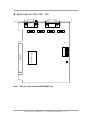
2.1 Board Layout
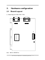
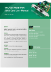
Board layout of the VXC-112A
CON1
CON2
SW1
8 7654 3 2 1
PCI controller
PCI BUS
LED
Note: CN1/2 => RS-232 Port
VXC Cards User’s Manual (Ver. 1.1, 06/09.2005, pmh-012-01) -----7
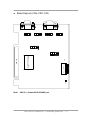
Board layout of the VXC -142
CN1
CN2
S1
876543 21
LED
PCI controller
PCI BUS
Note: CN1/2 => Non-Isolated RS-422/485 port
VXC Cards User’s Manual (Ver. 1.1, 06/09.2005, pmh-012-01) -----8
Board layout of the VXC-142i
CN1
CN2
S1
8 7654 3 2 1
PCI controller
PCI BUS
LED
Note: CN1/2 => Isolated RS-422/485 port
VXC Cards User’s Manual (Ver. 1.1, 06/09.2005, pmh-012-01) -----9
Board layout of the VXC-182i
CN1
CN2
S1
8 7654 3 2 1
PCI controller
PCI BUS
LED
Note: CN1 => Isolated RS-422/485 port
CN2 => RS-232 port
VXC Cards User’s Manual (Ver. 1.1, 06/09.2005, pmh-012-01) -----10
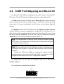
2.2 COM Port Mapping and Board ID
The Board ID and COM port mapping are the same, which is set by the S1
DIP switch. The S1 DIP switch has different functions under different OS.
For DOS users, the S1 DIP switch acts as Board ID. When there are two or
more multi-port serial cards in a single system, it is difficult to identify individual
card number. For easier identification, the VXC series card includes a Board ID
function.
For Windows users, the S1 DIP switch acts as COM port number selector
and the COM port number is depending on the Board ID. If the Board ID is 0,
then the driver finds a valid number for each port. If the Board ID is not 0, then
the driver uses the “Board ID” to be the first COM port number and uses the
“Board ID +1” to be the next COM port number and so on.
Note: It’s recommended to select a unique COM port number (Board
ID) by users. This helps users to identify and fix these cards and ports
in a system without confuses.
Note: The port will not work if the COM port number is conflicted under
Windows or Linux system. In that case, users should try other COM port
numbers.
Usually, the COM1 and COM2 are reserved by systems. And it’s
recommended to reserve the COM3 and COM4 if you will have other
Plug&Play serial ports in the future. This prevents confliction.
For Linux users, it’s the same as Windows users but for TTY device
number selector.
The configuration examples are as follows.
S1
87654321
ON
VXC Cards User’s Manual (Ver. 1.1, 06/09.2005, pmh-012-01) -----11
S1 DIP Switch
Board ID=0x00 (Default)
8
7
6
5
4
3
2
1
OFF
OFF
OFF
OFF
OFF
OFF
OFF
OFF
OFF
OFF
OFF
OFF
OFF
OFF
ON
ON
OFF
OFF
OFF
OFF
OFF
ON
OFF
ON
OFF
OFF
OFF
OFF
OFF
ON
ON
ON
OFF
OFF
OFF
OFF
ON
OFF
OFF
ON
OFF
OFF
OFF
ON
OFF
ON
OFF
OFF
OFF
OFF
OFF
ON
ON
ON
ON
OFF
OFF
OFF
ON
OFF
ON
OFF
OFF
OFF
OFF
OFF
ON
ON
OFF
OFF
ON
OFF
OFF
OFF
ON
ON
ON
ON
OFF
OFF
OFF
ON
ON
OFF
OFF
ON
OFF
OFF
ON
OFF
OFF
ON
OFF
ON
ON
OFF
ON
ON
OFF
OFF
ON
OFF
OFF
OFF
ON
ON
ON
ON
ON
ON
ON
ON
COM = Auto-defined
Board ID=0x03
COM = 3/4
Board ID=0x05
COM = 5/6
Board ID=0x07
COM = 7/8
Board ID=0x09
COM = 9/10
Board ID=0x14
COM = 20/21
Board ID=0x1E
COM = 30/31
Board ID=0x28
COM = 40/41
Board ID=0x32
COM = 50/51
Board ID=0x3C
COM = 60/61
Board ID=0x64
COM = 100/101
Board ID=0x96
COM = 150/151
Board ID=0xC8
COM = 200/201
.
.
.
Board ID=0xFF
COM = 255/256
VXC Cards User’s Manual (Ver. 1.1, 06/09.2005, pmh-012-01) -----12
2.3 Pin Assignment and Cable Wiring
2.3.1 RS-422 Cable Wiring
CH1~ 2
TxD-
1
TxD+
2
6
RTS-
7
RTS+
8
CTS+
9
CTS-
RxD+ 3
RxD-
4
GND
5
DB9(M)
VXC-142/142i, VXC-182i DTE (MALE DB-9)
Terminal DTE (DB-9)
PIN
Signal
PIN
Signal
1
TxD-
4
RxD-
2
TxD+
3
RxD+
3
RxD+
2
TxD+
4
RxD-
1
TxD-
5
GND
5
GND
6
RTS-
9
CTS-
7
RTS+
8
CTS+
8
CTS+
7
RTS+
9
CTS-
6
RTS-
2.3.2 RS-485 Cable Wiring
CH1~ 2
DATA- 1
6
DATA+2
7
3
8
4
9
5
DB9(M)
VXC-142/142i, VXC-182i DTE (MALE DB-9)
Terminal DTE (DB-9)
PIN
Signal
PIN
Signal
1
DATA -
1
DATA -
2
DATA +
2
DATA +
VXC Cards User’s Manual (Ver. 1.1, 06/09.2005, pmh-012-01) -----13
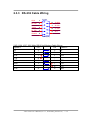
2.3.3 RS-232 Cable Wiring
CH2
CD
1
RxD
2
TxD
3
DTR
4
GND
5
6
DSR
7
RTS
8
CTS
9
RI
DB9(M)
VXC-112A, VXC-182i (Male DB-9) Null Modem Cable Wiring
System 1
Pin
Pin
TX
3
2
RX
RX
2
3
TX
RTS
7
1
DCD
CTS
8
-
DSR
6
4
DTR
DCD
1
7
RTS
-
8
CTS
4
6
DSR
DTR
System 2
VXC Cards User’s Manual (Ver. 1.1, 06/09.2005, pmh-012-01) -----14
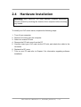
2.4
Hardware Installation
Warning: Static electricity can easily damage computer equipment.
Ground yourself by touching the chassis of the computer before touching
any boards.
To install your VXC series cards, complete the following steps:
1.
2.
3.
4.
5.
Turn off your computer
Remove all covers from the computer
Select an unused PCI slot
Remove the PCI slot cover from the PC
Carefully insert your VXC card into the PCI slot, and attach the cable to the
connector
6. Replace the PC cover
7. Turn on your PC and refer to Chapter 3 for information regarding software
installation
VXC Cards User’s Manual (Ver. 1.1, 06/09.2005, pmh-012-01) -----15
3.
Software Installation
ICP DAS provides following device drivers for most operation systems such
as MS-DOS, Windows NT 4.0 and Windows 2000/XP/2003. These Windows
drivers provide full interrupt-driven, buffered I/O for each COM ports. And also
supports the Plug & Play mechanism for easy installation.
VxCard DOS Lib: Programming library files and sample programs for DOS.
VxCard Driver NT: COM port driver for Windows NT 4.0.
VxCard Driver 2K: COM port driver for Windows 2000/XP/2003.
VxCard Driver Linux: tty driver for Linux.
Note: VxCard Driver 2K also supports Windows XP and Windows
Server 2003.
For Windows users to access COM ports, please refer to the “Serial
Communications in Win32” article for programming information. Which can be
found by searching on the http://msdn.microsoft.com.
This chapter shows you the detail steps to install these drivers.
Note: For more information about COM port number selection,
please refer to Section 2.2 “COM Port Mapping & Board ID”.
VXC Cards User’s Manual (Ver. 1.1, 06/09.2005, pmh-012-01) -----16
3.1 DOS Lib
Microsoft provides standard Win32 APIs for Windows 9x/NT/2K/XP/2003
users to access the COM ports. But DOS did not have such standard APIs, thus
ICP DAS provides library functions under DOS for the VXC cards. Which
provides easy programming interfaces and sample programs (include source
code) that written in Turbo C.
These sample programs (include source code) show you …
1. To find out all VXC cards.
2. To get the I/O address and IRQ number of the card.
3. To get the Board ID of the card.
4. To Send/receive data to/from the COM ports.
5. To control the LED On/Off of the card.
3.1.1 Installation
Please refer to the “Release Note” paper that shows you the location of the
software on the CD. Run the “install.bat” batch file to install the software into
your c: disk.
If you like to install the software into a different location, you can specify the
parameter after the “install.bat” file. For example:
Install d:\MyProj <Enter>
Or, you can copy the folder into your project directory manually.
VXC Cards User’s Manual (Ver. 1.1, 06/09.2005, pmh-012-01) -----17
3.2 Windows NT 4.0
3.2.1 Installation
Please refer to the “Release Note” paper to see the software location and
refer to the following steps to complete it.
Note: It’s recommended to install the software first, and then the
hardware. This reduces the reboot times of your computer.
1. Launch the “VxCardNT.exe” setup program, and then click the “Next >”
button.
2. When prompted, click the “Next >” button to start installation. Or click the
“Change…” button to select a new folder first for the installation.
3. After the driver is installed, click the “Finish” button.
4. When prompted, select the “Yes, I want to restart my computer now.”
option, and then click the “Finish” button to reboot the computer.
Note: After the installation is completed, users must restart the
computer to start the driver.
3.2.2 Verification
ICP DAS provides a ”VxCard Utility” program (VxCardUtil.exe) for users to
see all the COM ports on the system. It shows COM ports in two gorups, one for
VXC Card and one for others. So, users can check if any confliction occurred
between COM ports.
To launch the utility, just double-click on the ”VxCard Utility” short-cut on
your desktop.
VXC Cards User’s Manual (Ver. 1.1, 06/09.2005, pmh-012-01) -----18
Note: When the hardware and software are well installed, the driver turns
off the LED on the card. If there is something error, such as driver not
work or COM port number conflicted, the LED keeps lighting.
3.2.3 Configuration
If need, users can change the input buffer size (default is 4KB for each port,
up to 128KB) by setting the “SW FIFO” scroll-bar on the VxCard Utility.
To change the COM port mappings, users should restart the driver by
rebooting the computer, or launch a DOS box and run …
“Net Stop VxCarSer” command to stop the driver, then run
“Net Start VxCarSer” command to start the driver again.
3.2.4 Uninstallation
1. Select the “Start / Settings / Control Panel” and double-click the
“Add/Remove Programs” icon.
2. Select the “VxCard Driver NT” and click the “Add/Remove” button.
VXC Cards User’s Manual (Ver. 1.1, 06/09.2005, pmh-012-01) -----19
3.3 Windows 2000
3.3.1 Installation
Note: It’s recommended to install the software first, and then the
hardware. This reduces the configuration procedures.
1. Launch the VxCard2K.exe to install the driver and register the related
information onto the system.
2. Power off the computer and install the VxCard into the PC.
3. Power on your computer, Windows 2000 should find the new card and load
the driver automatically. (Sometimes Win2K pops up few confirm dialog box,
just click “next” or “OK” to finish it.)
3.3.2 Verification
To verify the installation, please complete the following steps:
1.
2.
Select ”Start/Settings/Control Panel” and double-click the ”System” icon.
Click the ”Hardware” tab and then click the ”Device Manager” button.
The VXC Card is listed under the ”VXC Multi-port serial Card” class, and
each Communications Port is listed under the ”Ports (VxCard – RS232/422/485)” class.
VXC Cards User’s Manual (Ver. 1.1, 06/09.2005, pmh-012-01) -----20
Note: When the hardware and software are well installed, the
driver turns off the LED on the card. If there is something error,
such as driver not work or COM port number conflicted, the LED
keeps lighting.
3.3.3
Configuration
If need, users can change the input buffer size (default is 4KB for each port,
up to 128KB) by setting the “SW FIFO” scroll-bar on the VxCard Utility. The
utility’s short cut is placed on the desktop after installation.
To change the COM port mappings, users should restart the driver by
rebooting the computer, or re-install the “VXC Card” hardware in the “Device
Manager” by un-install card and then scan new hardware.
3.3.4 Uninstallation
Before removing the card from your computer, it’s recommended to uninstall
the device from the ”Device Manager”. This removes unused hardware
information from the database (registry) of Windows.
VXC Cards User’s Manual (Ver. 1.1, 06/09.2005, pmh-012-01) -----21
3.4
Windows XP/2003
3.4.1 Installation
Note: It’s recommended to install the software first, and then the
hardware. This reduces the configuration procedures.
1. Launch the VxCard2K.exe to install the driver and register the related
information onto the system. (Win2K driver also works on XP/Server 2003.)
2. Power off the computer and install the VxCard into the PC.
3. Power on your computer, Windows XP/2003 should find the new card and
load the driver automatically. (WinXP/2003 may pop up few confirm dialog
box, just click “next” or “OK” to finish it.)
3.4.2 Verification
To verify the installation, please complete the following steps:
1. Select ”Start/Settings/Control Panel” and double-click the ”System” icon.
2. Click the ”Hardware” tab and then click the ”Device Manager” button.
The VXC Card is listed under the ”VXC Multi-port serial Card” class, and
each Communications Port is listed under the ”Ports (VxCard – RS232/422/485)” class.
VXC Cards User’s Manual (Ver. 1.1, 06/09.2005, pmh-012-01) -----22
Note: When the hardware and software are well installed, the driver turns
off the LED on the card. If there is something error, such as driver not
work or COM port number conflicted, the LED keeps lighting.
3.4.3 Configuration
If need, users can change the input buffer size (default is 4KB for each port,
up to 128KB) by setting the “SW FIFO” scroll-bar on the VxCard Utility. The
utility’s short cut is placed on the desktop after installation.
To change the COM port mappings, users should restart the driver by
rebooting the computer, or re-install the “VXC Card” hardware in the “Device
Manager” by un-install card and then scan new hardware.
3.4.4 Uninstallation
Before removing the card from your computer, it’s recommended to uninstall
the device from the ”Device Manager”. This removes unused hardware
information from the database (registry) of Windows.
VXC Cards User’s Manual (Ver. 1.1, 06/09.2005, pmh-012-01) -----23
3.5
Linux
This section describes VXC Card Linux driver’s features and how to compile
and install into a general Linux system. The VXC Card Linux driver is modified
from Linux kernel source and supports most of popular PC-based Linux
distributions.
3.5.1 Driver Features
Device file.
Dynamic device allocation.
Dynamic major number.
One major number for multiple devices.
Use the GNU configure and build system.
3.5.2 Installation
Please refer to the following steps to complete it.
1. Download or copy the IxCOM package to a directory that you have access to.
2. Extract the package.
For example, the package's file name is "ixcom-0.05.0.tar.gz" and its
path related to your current working directory is../pkg, then the extraction
command would be
gunzip -c ../pkg/ixcom-0.05.0.tar.gz | tar xvf –
or
tar -zxvf ../pkg/ixcom-0.05.0.tar.gz
An ixcom-0.05.0 directory is created after extraction.
3. For convenient access, it is a good idea to put a symbol-link on it.
ln -s ixcom-0.05.0 ixcom
4. Change to the ixcom working directory you just made, type
./configure to create proper Makefiles.
VXC Cards User’s Manual (Ver. 1.1, 06/09.2005, pmh-012-01) -----24
5. Once the configuring has done successfully, type “make” to build all.
Note: If you like to install files to system directory, the make install will
do it for you. However, install files to system directory is not necessary
for further operation. You will need the root privilege for that.
Script
“./ixcom.inst”
loads
modules
automatically.
Script
“./ixcom.remove” removes the loaded modules. The root privilege is required
when installing or removing these kernel modules.
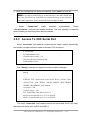
3.5.3 Access To VXC Serial Port
Script “ixcom.inst” will establish unused device major number dynamically
and create correspond device node for access VXC serial port.
# ./ixcom.inst
IxCOM Installer 0.4.0
Check kernel version... 2.4
Use proc-file /proc/icpdas/ixcom
Load module ixcom
Use “dmesg” command to inspect the driver output message.
dmesg
………
………
ICPDAS VXC multi-serial card Serial driver version 5.05c
(2001-07-08) with HUB-6 MANY_PORTS MULTIPORT
SHARE_IRQ SERIAL_PCI enabled
vxc major = 254
vxc aux_major = 253
PCI: Found IRQ 5 for device 00:13.0
ttySV0 at port 0xe0c0 (irq = 5) is a 16550A
ttySV1 at port 0xe0e0 (irq = 5) is a 16550A
The script “ixcom.inst” had loaded module into kernel and find a VXC card
that have two serial port, ttySV0 and ttySV1.
VXC Cards User’s Manual (Ver. 1.1, 06/09.2005, pmh-012-01) -----25
The “ixcom.inst” script will use major number 254 to create correspond
device on the /dev.
# ls -la /dev/ttySV?
crw-rw-rw- 1 root
crw-rw-rw- 1 root
crw-rw-rw- 1 root
crw-rw-rw- 1 root
crw-rw-rw- 1 root
crw-rw-rw- 1 root
crw-rw-rw- 1 root
crw-rw-rw- 1 root
crw-rw-rw- 1 root
crw-rw-rw- 1 root
root
root
root
root
root
root
root
root
root
root
254,
254,
254,
254,
254,
254,
254,
254,
254,
254,
64 Jul 14 10:13 /dev/ttySV0
65 Jul 14 10:13 /dev/ttySV1
66 Jul 14 10:13 /dev/ttySV2
67 Jul 14 10:13 /dev/ttySV3
68 Jul 14 10:13 /dev/ttySV4
69 Jul 14 10:13 /dev/ttySV5
70 Jul 14 10:13 /dev/ttySV6
71 Jul 14 10:13 /dev/ttySV7
72 Jul 14 10:13 /dev/ttySV8
73 Jul 14 10:13 /dev/ttySV9
To remove VXC driver from system use script “./ixcom.remove” to
removes the loaded modules.
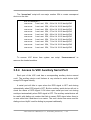
3.5.4 Access to VXC Auxiliary Serial Port
Each port of the VXC card has a corresponding auxiliary device named
cuaV. The auxiliary device cuaV behave is very similar to serial device ttySV
except DCD signal identify.
A serial port will fails to open when the DCD signal is OFF and closing
automatically when DCD signal is OFF. But the auxiliary serial device will not to
check the status of DCD signal if ON when open serial port and not closing
serial port automatically when DCD signal is OFF. The auxiliary serial device will
be useful with dialing-out modem that fails to assert DCD signal when there is
no one called into it and there is no carrier. The cuaV device was once used for
dialing-out and ttySV used for dialing-in purpose traditionally.
VXC Cards User’s Manual (Ver. 1.1, 06/09.2005, pmh-012-01) -----26
Each ttySV device of VXC serial card has a corresponding auxiliary device
cuaV with the same minor number but different major number that create by
script ixcom.inst automatically.
# ls -la /dev/cuaV?
crw-rw-rw- 1 root
crw-rw-rw- 1 root
crw-rw-rw- 1 root
crw-rw-rw- 1 root
crw-rw-rw- 1 root
crw-rw-rw- 1 root
crw-rw-rw- 1 root
crw-rw-rw- 1 root
crw-rw-rwcrw-rw-rw-
root
root
root
root
root
root
root
root
253,
253,
253,
253,
253,
253,
253,
253,
64 Jul 14 10:13 /dev/cuaV0
65 Jul 14 10:13 /dev/cuaV1
66 Jul 14 10:13 /dev/cuaV2
67 Jul 14 10:13 /dev/cuaV3
68 Jul 14 10:13 /dev/cuaV4
69 Jul 14 10:13 /dev/cuaV5
70 Jul 14 10:13 /dev/cuaV6
71 Jul 14 10:13 /dev/cuaV7
1 root root 253, 72 Jul 14 10:13 /dev/cuaV8
1 root root 253, 73 Jul 14 10:13 /dev/cuaV9
VXC Cards User’s Manual (Ver. 1.1, 06/09.2005, pmh-012-01) -----27
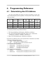
4. Programming Reference
4.1 Determining the I/O Address
The plug & play BIOS will assign the correct I/O address to each VXC
series card during the power-up process. The fixed IDs of each VXC series
card is as follows:
Item
Vendor ID
Device ID
SubVendor ID
SubDevice ID
Sub-Aux
ID
VXC-112A
0xe159
0x0001
0x1D61
0x0000
0x00
VXC-142
0xe159
0x0001
0x0061
0x0000
0x00
VXC-142i
0xe159
0x0001
0x0161
0x0002
0x00
VXC-182i
0xe159
0x0001
0x0161
0x0001
0x00
All necessary functions are provided as follows:
1. PIO_DriverInit(&wBoard, wSubVendor, wSubDevice, wSubAux)
2. PIO_GetConfigAddressSpace(wBoardNo,*wBase,*wIrq, *wSubVendor,
*wSubDevice, *wSubAux, *wSlotBus, *wSlotDevice)
3. Show_PIO_PISO(wSubVendor, wSubDevice, wSubAux)
All functions are defined in PIO.H. The important driver information is as follows:
1. Resource-allocated information:
• wBase : BASE address mapping in the PC
• wIrq:
The IRQ channel number allocated in the PC
2. VXC identification information:
• wSubVendor:
The subVendor ID of the board
• wSubDevice:
The subDevice ID of the board
• wSubAux:
The subAux ID of the board
3. PC’s physical slot information:
• wSlotBus:
The slot position of hardware slot ID1 in the PC
• wSlotDevice:
The slot position of hardware slot ID2 in the PC
VXC Cards User’s Manual (Ver. 1.1, 06/09.2005, pmh-012-01) -----28
The PIO_PISO.EXE utility program will detect and display all VXC cards
installed in the PC.
4.1.1 PIO_DriverInit
PIO_DriverInit(&wBoards, wSubVendor, wSubDevice, wSubAux)
•
•
•
•
wBoards
wSubVendor
wSubDevice
wSubAux
[OUT] number of boards found in this PC
[IN] Sub-vendor ID of the board to be determined
[IN] Sub-device ID of the board to be determined
[IN] Sub-aux ID of the board to be determined
Note: The “[IN]” symbolic indicates that the parameter should assign a
value by users, while the “[OUT]” symbolic indicates that the parameter
will return a value after calling the function.
The PIO_DriverInit function detects all VXC series cards in the system, and
is implemented based on the PCI plug & play mechanism. All VXC series cards
installed in this system will be detected and the resources will be saved in the
library.
Sample program 1:
Determine the resources for all VXC-142 cards in the PC
wSubVendor=0x61; wSubDevice=0x00; wSubAux=0x00; /* for VXC-142 */
wRetVal=PIO_DriverInit(&wBoards, wSubVendor,wSubDevice,wSubAux);
printf("There are %d VXC-142 card(s) in this PC\n",wBoards);
/* Step 2: save the resources of all cards installed in the PC */
for (i=0; i<wBoards; i++)
{ PIO_GetConfigAddressSpace(i,&wBase,&wIrq,&wID1,&wID2,&wID3,
&wID4,&wID5);
printf("\nCard_%d: wBase=%x, wIrq=%x", i,wBase,wIrq);
wConfigSpace[i][0]=wBaseAddress; /* save all resources of this card */
wConfigSpace[i][1]=wIrq;
/* save all resources of this card */
}
VXC Cards User’s Manual (Ver. 1.1, 06/09.2005, pmh-012-01) -----29
Sample program 2:
Identify all VXC cards in the PC
wRetVal=PIO_DriverInit(&wBoards,0xff,0xff,0xff); /* identify all VXC cards */
printf("\nThere are %d VXC Cards in this PC",wBoards);
if (wBoards==0 ) exit(0);
printf("\n-----------------------------------------------------");
for(i=0; i<wBoards; i++)
{
PIO_GetConfigAddressSpace(i,&wBase,&wIrq,&wSubVendor,
&wSubDevice,&wSubAux,&wSlotBus,&wSlotDevice);
printf("\nCard_%d:wBase=%x,wIrq=%x,subID=[%x,%x,%x],
SlotID=[%x,%x]",i,wBase,wIrq,wSubVendor,wSubDevice,
wSubAux,wSlotBus,wSlotDevice);
printf(" --> ");
ShowPioPiso(wSubVendor,wSubDevice,wSubAux);
}
4.1.2 PIO_GetConfigAddressSpace
PIO_GetConfigAddressSpace(wBoardNo,*wBase,*wIrq, *wSubVendor,
*wSubDevice,*wSubAux,*wSlotBus, *wSlotDevice)
• wBoardNo
[IN] Board index number which between 0 and total boards –1.
•
•
•
•
•
•
•
wBase
wIrq
wSubVendor
wSubDevice
wSubAux
wSlotBus
wSlotDevice
[OUT] The base address of this board.
[OUT] The IRQ channel number allocated to this board.
[OUT] The sub-vendor ID for this board.
[OUT] The sub-device ID for this board.
[OUT] The sub-aux ID for this board.
[OUT] The hardware slot ID1 for this board.
[OUT] The hardware slot ID2 for this board.
The PIO_GetConfigAddressSpace function can be used to save the
resource information for all VXC cards installed in the system. The application
program can then directly control the functions of each VXC series card.
A sample program source is as follows:
VXC Cards User’s Manual (Ver. 1.1, 06/09.2005, pmh-012-01) -----30
/* Step 1: detect all VXC-142 cards */
wSubVendor=0x61; wSubDevice=0x00; wSubAux=0x00;/* for VXC-142 */
wRetVal=PIO_DriverInit(&wBoards, wSubVendor,wSubDevice,wSubAux);
printf("There are %d VXC-142 cards in this PC\n",wBoards);
/* Step 2: save the resources for each VXC-142 card installed in the PC */
for (i=0; i<wBoards; i++)
{ PIO_GetConfigAddressSpace(i,&wBase,&wIrq,&t1,&t2,&t3,&t4,&t5);
printf("\nCard_%d: wBase=%x, wIrq=%x", i,wBase,wIrq);
wConfigSpace[i][0]=wBaseAddress; /* save all resources for this card */
wConfigSpace[i][1]=wIrq;
/* save all resources for this card */
}
/* Step 3: directly control the VXC-142 */
wBase=wConfigSpace[0][0];
/* get the base address of card_0 */
outport(wBase,1);
/* enable all D/I/O operations for card_0 */
wBase=wConfigSpace[1][0];
/* get the base address of card_1 */
outport(wBase,1);
/* enable all D/I/O operations for card_1 */
4.1.3 Show_PIO_PISO
Show_PIO_PISO(wSubVendor,wSubDevice,wSubAux)
•
•
•
wSubVendor
wSubDevice
wSubAux
[IN] the subVendor ID of the board to be determined
[IN] the subDevice ID of the board to be determined
[IN] the subAux ID of the board to be determined
The Show_PIO_PISO function will display a text string to identify the special
subIDs. The text string is the same as that defined in PIO.H
A demo program is as follows:
VXC Cards User’s Manual (Ver. 1.1, 06/09.2005, pmh-012-01) -----31
wRetVal=PIO_DriverInit(&wBoards,0xff,0xff,0xff); /*find all VXC*/
printf("\nThere are %d VXC Cards in this PC",wBoards);
if (wBoards==0 ) exit(0);
printf("\n-----------------------------------------------------");
for(i=0; i<wBoards; i++)
{
PIO_GetConfigAddressSpace(i,&wBase,&wIrq,&wSubVendor,
&wSubDevice,&wSubAux,&wSlotBus,&wSlotDevice);
printf("\nCard_%d:wBase=%x,wIrq=%x,subID=[%x,%x,%x],
SlotID=[%x,%x]",i,wBase,wIrq,wSubVendor,wSubDevice,
wSubAux,wSlotBus,wSlotDevice);
printf(" --> ");
ShowPioPiso(wSubVendor,wSubDevice,wSubAux);
}
VXC Cards User’s Manual (Ver. 1.1, 06/09.2005, pmh-012-01) -----32
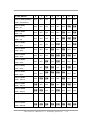
4.2 I/O Address Mapping
The I/O address of the VXC series card is automatically assigned by the
main-board ROM BIOS. The I/O address can also be re-assigned by the user. It
is strongly recommended that user does not change the I/O address. The
plug & play BIOS will assign the correct I/O address to each VXC series
card.
The table below indicates the I/O address of the VXC-112A, VXC-142/142i
and VXC-182i series cards:
Address
Read
Write
wBase+0
Same
RESET\ control register
wBase+2
Same
Aux control register
wBase+3
Same
Aux data register
wBase+5
N/A
INT mask control register
wBase+7
Aux pin status register
Same
wBase+0x2a
N/A
INT polarity control register
wBase+0xc0
Read Data from Port 1
Write Data to Port 1
wBase+0xe0
Read Data from Port 2
Write Data to Port 2
wBase+0xdc
High/low speed mode of Port 1
wBase+0xfc
High/low speed mode of Port 2
Note. Refer to Sec. 4.1 for more information regarding wBase.
VXC Cards User’s Manual (Ver. 1.1, 06/09.2005, pmh-012-01) -----33
4.2.1 RESET\ Control Register
(Read/Write): wBase+0
Bit 7
Bit 6
Bit 5
Bit 4
Bit 3
Bit 2
Bit 1
Bit 0
Reserved Reserved Reserved Reserved Reserved Reserved Reserved RESET\
Note. Refer to Sec. 4.1 for more information regarding wBase.
When the PC is first powered-on, the RESET\ signal is in the Low state. This
will disable all D/I/O operations. The user must set the RESET\ signal to the
High state before sending any D/I/O commands.
outportb(wBase,1);
outportb(wBase,0);
/* RESET\ = High
/* RESET\ = Low
all D/I/O are now enabled */
all D/I/O are now disabled */
4.2.2 AUX Control Register
(Read/Write): wBase+2
Bit 7
Bit 6
Bit 5
Bit 4
Bit 3
Bit 2
Bit 1
Bit 0
Aux7
Aux6
Aux5
Aux4
Aux3
Aux2
Aux1
Aux0
Note. Refer to Sec. 4.1 for more information regarding wBase.
Aux n=0
Aux n=1
the Aux is used as an input.
the Aux is used as an output.
n=0~7
When the PC is first powered-on, all Aux n signals are in the Low state.
Each Aux n is designed as an input for all VXC series cards.
VXC Cards User’s Manual (Ver. 1.1, 06/09.2005, pmh-012-01) -----34
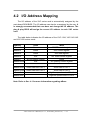
4.2.3 AUX data Register
(Read/Write): wBase+3
Bit 7
Bit 6
Bit 5
Bit 4
Bit 3
Bit 2
Bit 1
Bit 0
Aux7
Aux6
Aux5
Aux4
Aux3
Aux2
Aux1
Aux0
Note. Refer to Sec. 4.1 for more information regarding wBase.
This register is designed for LED controls. Before controlling LED state,
users have to configure the related Aux? to be an output.
Aux5: For VXC-112A LED controls.
Aux7: For VXC-142/142i and VXC-182i LED controls.
outportb(wbase+2,0x80);
outportb(wBase+3,0);
outportb(wBase+3,0x80);
/* Set Aux7 is used as an output*/
/* turns the LED off */
/* turns the LED on */
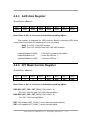
4.2.4 INT Mask Control Register
(Read/Write): wBase+5
Bit 7
Bit 6
Bit 5
Bit 4
Bit 3
Bit 2
Bit 1
Bit 0
0
0
0
0
EN3
EN2
EN1
EN0
Note. Refer to Sec. 4.1 for more information regarding wBase.
EN0~EN1 (INT_CH0 ~ INT_CH1): (CH0 offset = 0)
For VXC-142/142i and VXC-182i Interrupt Mask.
EN2~EN3 (INT_CH0 ~ INT_CH1): (CH0 offset = 2)
For VXC-112A Interrupt Mask.
EN? =0
EN? =1
disables INT_CHAN_? as an interrupt signal (default)
enables INT_CHAN_? as an interrupt signal
VXC Cards User’s Manual (Ver. 1.1, 06/09.2005, pmh-012-01) -----35
outportb(wBase+5, 0);
outportb(wBase+5,0x03);
outportb(wBase+5,0x0B);
/* disables all interrupts */
/* enables INT ch0 and ch1 for VXC-142 */
/* enables INT ch0 and ch1 for VXC-112A */
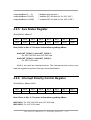
4.2.5 Aux Status Register
(Read/Write): wBase+7
Bit 7
Bit 6
Bit 5
Bit 4
Bit 3
Bit 2
Bit 1
Bit 0
Aux7
Aux6
Aux5
Aux4
Aux3
Aux2
Aux1
Aux0
Note. Refer to Sec. 4.1 for more information regarding wBase.
Aux0=INT_CHAN_0, Aux1=INT_CHAN_1:
For VXC-142/142i and VXC-182i card.
Aux2=INT_CHAN_0, Aux3=INT_CHAN_1:
For VXC-112A card.
Aux0~3 are used as interrupt sources. The interrupt service routine must
read this register to perform interrupt source identification.
4.2.6 Interrupt Polarity Control Register
(Read/Write): wBase+0x2A
Bit 7
Bit 6
Bit 5
Bit 4
Bit 3
Bit 2
Bit 1
Bit 0
0
0
0
0
INV3
INV2
INV1
INV0
Note. Refer to Sec. 4.1 for more information regarding wBase.
INV0~INV1: For VXC-142/142i and VXC-182i card.
INV2~INV3: For VXC-112A card.
VXC Cards User’s Manual (Ver. 1.1, 06/09.2005, pmh-012-01) -----36
INV? =0
INV? =1
selects the inverted signal from INT_CHAN_?
selects the non-inverted signal from INT_CHAN_?
outportb(wBase+0x2a,0);
/* selects the inverted input from all 8 channels */
outportb(wBase+0x2a,0xFF); /* selects the non-inverted input from all 8 channels */
// For VXC-142/142i and VXC-182i
outportb(wBase+0x2a,0x2);
/* selects the inverted input of INT_CHAN_0 */
/* selects the non-inverted input of INT_CHAN_1 */
// For VXC-112A
outportb(wBase+0x2a,0x8);
/* selects the inverted input of INT_CHAN_0 */
/* selects the non-inverted input of INT_CHAN_1 */
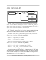
4.2.7 Speed selection
(Read/Write): wBase+0xdc/0xfc
Bit 7
Bit 6
Bit 5
Bit 4
Bit 3
Bit 2
Bit 1
Bit 0
N/A
N/A
N/A
N/A
N/A
N/A
Speed
N/A
Mode
Clock Rate
Baud Rate
Remark
Low Speed (0)
1,843,200Hz
50 bps ~115.2K bps
(Default)
High Speed (2)
14,745,600Hz
400 bps ~ 921.6K bps
Note. Refer to Sec. 4.1 for more information regarding wBase.
outportb(wAddr+0xdc, 0);
outportb(wAddr+0xfc, 0);
/* low speed mode for port 1 */
/* low speed mode for port 2 */
outportb(wAddr+0xdc, 2);
outportb(wAddr+0xfc, 2);
/* high speed mode for port 1 */
/* high speed mode for port 2 */
VXC Cards User’s Manual (Ver. 1.1, 06/09.2005, pmh-012-01) -----37
4.3 Interrupt Operation
There are two interrupt sources in the VXC cards. They are named as INT0
and INT1. Their signal sources are as follows:
INT0: UART 0 interrupt output
INT1: UART 1 interrupt output
If only one interrupt signal source is used, the interrupt service routine doesn’t
need to identify the interrupt source.
If there is more than one interrupt source, the interrupt service routine needs
to identify the active signals by:
1. Reading the new status of all interrupt signal sources
2. Servicing it if INT0 is active
3. Servicing it if INT1 is active
Note:
If the interrupt signal is too short, the interrupt service routine cannot
identify which interrupt source is active. Therefore, the interrupt signal
must be in the hold_active state long enough for the interrupt service
routine to be executed. The hold_time is different for different Operating
Systems. The hold_time can be as short as a microsecond or as long as a
whole second. In general, 20mS is a long enough to for successful
execution under any OS.
VXC Cards User’s Manual (Ver. 1.1, 06/09.2005, pmh-012-01) -----38
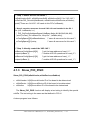
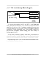
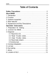
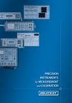
4.3.1 VXC Card Interrupt Block Diagram
INT\
INT_CHAN_0
Level_trigger
(to PCI slot)
INT_CHAN_1
initial_low
active_high
The interrupt output signal of the VXC card, INT\, is Level-Trigger and
Active_Low. If INT\ generates a low_pulse, the VXC card will send an interrupt
signal to the PC only once. If INT\ is fixed in low_level, the VXC card will send
an interrupt signal to the PC continuously. Therefore, INT_CHAN_0/1 must be
controlled as a pulse_type signal, which must normally be fixed in a
low_level state and should generate a high_pulse when sending an
interrupt signal to the PC.
The INT_CHAN_0/1 priority is the same as the above. If both signals are
active at the same time, then INT\ will activate only once. The interrupt service
routine must read the status of all interrupt channels for multi-channel interrupts.
If only one interrupt source is used, the interrupt service routine doesn’t need
to read the status of the interrupt source.
VXC Cards User’s Manual (Ver. 1.1, 06/09.2005, pmh-012-01) -----39
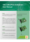
4.3.2
INT_CHAN_0/1
INT_CHAN_0/1
INT0/1
Inverted/Noninverted
select
(INV0/1)
Enable/Disable select
(EN0/1)
The INT_CHAN_0 and INT_CHAN_1 architecture is shown in the above
figure. The only difference between INT0 and INT1 is that the INT_CHAN_0
signal source comes from the UART 0 interrupt output, and the INT_CHAN_1
signal source comes from the UART 1 interrupt output.
INT_CHAN_0/1 must be fixed in a low level state normally and should
generate a high_pulse when sending an interrupt signal to the PC.
The EN0/1 can be used to enable/disable the INT_CHAN_0/1 as follows:
(Refer to Sec.4.2.4) (Note: VXC-112A using EN2/3.)
EN0/1 = 0 → INT_CHAN_0/1 = disabled
EN0/1 = 1 → INT_CHAN_0/1 = enabled
INV0/1 can be used to invert/non-invert the INT0/1 as follows:
(Refer to Sec.4.2.6) (Note: VXC-112A using INV2/3.)
INV0/1 = 0 → INT_CHAN_0/1 = inverted state of INT0/1
INV0/1 = 1 → INT_CHAN_0/1 = non-inverted state of INT0/1
As mentioned above, if INT\ is fixed in a low level state, the VXC card
will continuously send interrupt signals to the PC. The interrupt service
routine should use INV0/1 to invert/non-invert INT0/1 and so generate a
high_pulse. (Note: VXC-112A using INV2/3.)
VXC Cards User’s Manual (Ver. 1.1, 06/09.2005, pmh-012-01) -----40
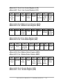
5. Appendix
UART Register Mapping
This section describes the UART register mapping for VXC cards. For more
information, please refer to the TI 16C550 datasheet.
wBase+0xC0: Port 0 Receiver Buffer Register (RBR)
wBase+0xE0: Port 1 Receiver Buffer Register (RBR)
Bit 7
Bit 6
Bit 5
Bit 4
Bit 3
Bit 2
Bit 1
Bit 0
Data 7
Data 6
Data 5
Data 4
Data 3
Data 2
Data 1
Data 0
wBase+0xC0: Port 0 Transmitter Holding Register (THR)
wBase+0xE0: Port 1 Transmitter Holding Register (THR)
Bit 7
Bit 6
Bit 5
Bit 4
Bit 3
Bit 2
Bit 1
Bit 0
Data 7
Data 6
Data 5
Data 4
Data 3
Data 2
Data 1
Data 0
wBase+0xC4: Port 0 Interrupt Enable Register (IER)
wBase+0xE4: Port 1 Interrupt Enable Register (IER)
Bit 7 Bit 6 Bit 5 Bit 4
0
0
0
0
Bit 3
Enable
Modem
Status
Interrupt
Bit 2
Bit 1
Enable
Enable
Transmitter
Receiver
Holding
Line Status
Register
Interrupt
Empty
Interrupt
Bit 0
Enable
Received
Data
Available
Interrupt
wBase+0xC8: Port 0 FIFO Control Register (FCR)
wBase+0xE8: Port 1 FIFO Control Register (FCR)
Bit 7
Bit 6
Bit 5
Bit 4
Bit 3
Bit 2
Bit 1
Bit 0
Receiver Receiver Reserved Reserved DMA Transmitter Receiver FIFO
FIFO Enable
FIFO
Mode
Trigger Trigger
Reset
Reset
Select
(LSB)
(MSB)
VXC Cards User’s Manual (Ver. 1.1, 06/09.2005, pmh-012-01) -----41
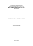
wBase+0xCC: Port 0 Line Control Register (LCR)
wBase+0xEC: Port 1 Line Control Register (LCR)
Bit 7
Divisor
Latch
Access
Bit
Bit 6
Break
Control
Bit 5
Stick
Parity
Bit 4
Even
Parity
Select
Bit 3
Parity
Enable
Bit 2
Bit 1
Number Word
Length
of
Stop Bits Select
Bit 1
Bit 0
Word
Length
Select
Bit 0
wBase+0xD0: Port 0 Modem Control Register (MCR)
wBase+0xF0: Port 1 Modem Control Register (MCR)
Bit 7
Bit 6
0
0
Bit 5
Autoflow
Control
Enable
Bit 4
Loop
Bit 3
OUT2
Bit 2
OUT1
Bit 1
Bit 0
Request
Data
to Send Terminal
Ready
wBase+0xD4: Port 0 Line Status Register (LSR)
wBase+0xF4: Port 1 Line Status Register (LSR)
Bit 7
Bit 6
Bit 5
Bit 4
Bit 3
Bit 2
Bit 1
Bit 0
Error in Transmitter Transmitter Break Framing Parity Overrun Data
Error Error Ready
Empty
Holding Interrupt Error
RCVR
Register
FIFO
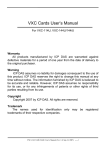
wBase+0xD8: Port 0 Modem Status Register (MSR)
wBase+0xF8: Port 1 Modem Status Register (MSR)
Bit 7
Bit 6
Bit 5
Ring
Data
Data
Set
Carrier Indicator
Ready
Detect
Bit 4
Clear to
Send
Bit 3
Bit 2
Trailing
Delta
Edge
Data
Ring
Carrier
Detect Indicator
Bit 1
Delta
Data
Set
Ready
wBase+0xDC: Port 0 Scratch Register (SCR)
wBase+0xFC: Port 1 Scratch Register (SCR)
VXC Cards User’s Manual (Ver. 1.1, 06/09.2005, pmh-012-01) -----42
Bit 0
Delta
Clear to
Send