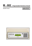
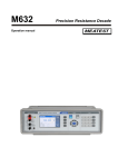
Download Specification
Transcript
PRECISION
INSTRUMENTS
for MEASUREMENT
and CALIBRATION
Production line
Multifunction Calibrators
Software for automatic Calibration
Camera Module
One-phase and Three-phase Power/Energy Calibrator
High Current AC/DC Calibrator
Impedance Calibrator
Resistance and Capacitance Programmable Boxes
RTD Temperature Sensor Simulator
Resistance Standards
Temperature/Humidity Meter
Precision Oil Bath
Electromagnetic Flowmeters
Company profile
Czech company MEATEST was found in 1991. Profile of company includes development,
manufacturing and sale of instruments especially for use in calibration laboratories and for accurate
measuring in industry. MEATEST is member of national metrology association Czech calibration
association, Czech metrology association and Calibration association of Slovak republic.
Production
Multifunction and process calibrators, standards, instruments for metrology of electric quantities.
Software and hardware accessories for computer-based automatic calibrations.
Special instruments for metrology like Temperature oil bathes, Programmable resistance decades etc.
Electromagnetic flowmeters for industrial application.
Quality management system & Traceability
MEATEST quality management system is certified according to standard ISO 9001:2000.
All main processes manufacturing, development, sale, services and calibrations are certified
and every year audited by Bureau Veritas Certification.
MEATEST main standards are traceable directly to the Czech national standards in Czech Metrology
Institute (CMI). CMI laboratories are accredited by Czech institute for accreditation, a member of
European co-operation for accreditation.
1
M-140 / M-142 Multifunction Calibrator Series
M-140
••
••
••
••
M-142
•• Build-in DC multimeter with
Voltage/Current/Resistance/Frequency
•• TC/RTD Temperature Sensor Simulation
•• GPIB and RS-232 as standard
AC/DC voltage/current to 1000V/30A
Best accuracy 15ppm in DCV mode
AC/DC Power/Energy, Phase shift
Resistance, Capacitance, Frequency
M-140/142 series represents category of multifunction calibrators of electric quantities for general application. Various versions offer
different range of electric functions, accuracies and user comfortability. Build-in multimeter enables complex testing and calibrating of
sources and meters of electric quantities. Multimeters, scopes, power meters, etc. can be directly calibrated with the instrument in sourcing
mode. In measuring mode, the calibrator can be used for testing of DC voltage/current sources, for temperature measurements and for
measuring other non-electric quantities through external sensors. Simultaneous generation and measurement allows calibration, adjusting
and testing of various types of regulators, panel-meters, converters, indicators etc.
Either manual control from the front panel keyboard, or remote control via GPIB bus or via RS-232 is available.
Model
DCV
accuracy
DCV ACV
DCI ACI
Shape
waveform
Power
Energy
RTD
TC
Built-in
Resistance Capacitance Frequency
Interface
simulation simulation
multimeter
M-140
35 ppm
1 000 V
20 A
Y
Y
Y
Y
50 MΩ
50 μF
20 MHz
Y
GPIB
RS232
M-142
15 ppm
1 000 V
30 A
Y
Y
Y
Y
1 000 MΩ
100 μF
20 MHz
Y
GPIB
RS232
M-140i
35 ppm
1 000 V
20 A
N
N
N
Y
N
N
N
N
RS232
M-142i
15 ppm
1 000 V
30 A
N
N
N
Y
N
N
N
N
RS232
M-140i
DC Voltage Ranges & Accuracy / 1 year
M-140 in 19˝ version
DC Current Ranges & Accuracy / 1 year
Range
M-140/M-140i [ppm of
value + V]
M-142/M-142i [ppm of
value + V]
Range
M-140/M-140i
[ppm of value + A]
M-142/M-142i
[ppm of value + A]
0 μV – 20 mV
300 + 10 μ
50 + 6 u
0 μA – 200 μA
500 + 20 nA
500 + 20 n
20 mV – 200 mV
100 + 15 μ
15 + 8 u
200 μA - 2 mA
200 + 100 nA
200 + 100 n
200 mV – 2 V
30 + 16 u
12 + 10 u
2 mA - 20 mA
100 + 600 nA
100 + 600 n
2 V - 20 V
30 + 100 u
10 + 50 u
20 mA – 200 mA
100 + 6 uA
100 + 6 u
20 V – 240 V
30 + 1 m
20 + 500 u
200 mA – 2 A
150 + 100 uA
150 + 100 u
240 V – 1000 V
50 + 50 m
50 + 20 m
2 A – 20 A *1
200 + 2 mA
200 + 2 m
20A – 30A *
—
300 + 3 m
1
* 1 Limited time of continuous current in range 10 to 30A
MEATEST, spol. s r. o., Zelezna 3, CZ - 619 00 Brno, Czech Republic | tel. +420 543 250 886, 887 | fax +420 543 250 890 | e-mail: [email protected] | www.meatest.com, www.meatest.cz
M-140, M-142/1
Specification
AC Voltage Ranges & Accuracy / 1 year
Range
1 mV - 20 mV
20 mV - 200 mV
200 mV - 2 V
2 V - 20 V
20 V – 240 V *3
240 V – 1000 V
M-140/M-140i
[ppm of value + V]
M-142/M-142i
[ppm of value + V]
M-140/M-140i M-142/M-142i
[ppm of value + V]
M-140/M-140i M-142/M-142i
[ppm of value + V]
20 Hz - 10 kHz
2 000 + 30 μ
1 000 + 80 μ
250 + 100 u
250 + 1 m
250 + 20 m
300 + 200 m *2
20 Hz - 10 kHz
2 000 + 30 μ
1 000 + 80 μ
180 + 100 u
180 + 1 m
180 + 20 m
300 + 200 m *2
10 kHz - 50 kHz
2000 + 1000 + 20 μ
1500 + 500 + 20 μ
500 + 200 μ
500 + 6 m
—
—
50 kHz - 100 kHz
1.0 + 0.10 + 20 μ
0.3 + 0.05 + 20 μ
0.2 + 1 m
0.2 + 10 m
—
—
M-140/M-140i
[ppm of value + A]
M-142/M-142i
[ppm of value + A]
M-140/M-140i M-142/M-142i
[ppm of value + A]
M-140/M-140i M-142/M-142i
[ppm of value + A]
20 Hz – 1 kHz
1500 + 20 n
700 + 200 n
500 + 1 u
500 + 10 u
500 + 100 u
1000 + 6 m
—
20 Hz – 1 kHz
1500 + 20 n
700 + 200 n
500 + 1 u
500 + 10 u
500 + 100 u
1000 + 6 m
20000 + 9 m
1 kHz – 5 kHz
3000 + 220 n
2000 + 1 μ
2000 + 10 μ
2000 + 100 μ
—
—
—
5 kHz – 10 kHz
—
5000 + 1400 n
5000 + 14 μ
5000 + 140 μ
—
—
—
* 2 valid for f < 1000 Hz; * 3 frequency in range 200 to 240 V is limited to 1 kHz
AC Current Ranges & Accuracy / 1 year
Range
1 μA – 200 μA
200 μA – 2 mA
2 mA - 20 mA
20 mA – 200 mA
200 mA - 2 A
10 A – 20 A *4 *6
20 A – 30 A *5
*4 Continuous output current maximum time is 60 sec for set value 20 A, for M-142 and 30 s for M-140.
* 5 Continuous output current maximum time is 30 sec for set value 30 A.
* 6 When Option 140-50 Current coil is used, add uncertainty 0.3 % of the set current to the value specified in the above table. Output current is multiplied by factor 50.
Function Shape (M-140 / M-142 versions only)
Range of voltage: Range of current:
Output waveform:
Peak value accuracy:
1 mV to 200 V
100 µA to 2 A
square, positive, negative, symmetrical, ramp A, ramp B, triangle, truncated sinus
0.3 %
Frequency (M-140 / M-142 versions only)
Type
Range
Frequency acc. [%]
Amplitude
Amplitude acc. [%]
Ratio [-]
Ratio acc. [-]
PWM (POS, NEG, SYM)
HSO *7
0.1 Hz–100 kHz
0.1 Hz–20 MHz
0.005
0.005
1 mV–10 V
5 Vpk-pk
0.1
10
0.1–0.99
—
0.0005
—
* 7 Rise time of generated output waveform in HSO function < 5 ns
Resistance (M-140 / M-142 versions only)
M-140
Capacitance (M-140 / M-142 versions only)
M-142
M-140
M-142
Range
ppm of value + mΩ
Range
ppm of value + mΩ
Range
% of value + pF
Range
% of value + pF
0 Ω – 100 Ω
100 Ω – 400 Ω
400 Ω – 2 kΩ
2kΩ – 10 kΩ
10 kΩ – 40 kΩ
40 kΩ – 200 kΩ
200kΩ – 1 MΩ
1 MΩ – 4 MΩ
4 MΩ – 20MΩ
20 MΩ – 50MΩ
300 + 10
150
150
150
150
150
500
1000
2000
5000
0–10 Ω
10 – 33 Ω
100 – 330 Ω
330–1 kΩ
1 – 3.3 kΩ
3.3–10 kΩ
10 – 33 kΩ
33 – 100 kΩ
100 – 330 kΩ
330 – 1 MΩ
1 – 3.3 MΩ
3.3–10MΩ
10 – 33 MΩ
33–100 MΩ
100 MΩ – 1 GΩ
300 + 5
150 + 5
100 + 5
100
100
100
100
100
100
100
200
500
1000
2000
5000
900 pF – 2.5 nF
2.5 nF – 10 nF
10 nF – 50 nF
50 nF–250 nF
250 nF – 1 μF
1 μF–3.5 μF
3.5 μF – 5 μF
5 μF–10 μF
10 μF – 50 μF
0.5 + 15
0.5
0.5
0.5
0.5
1
1
1.5
2.0
700 pF–1 nF
1 nF–3.3 nF
3.3 nF – 10 nF
10 nF–33 nF
33 nF–100 nF
100 nF–330 nF
330 nF – 1 μF
1 μF–3.3 μF
3.3 μF–10 μF
10 μF – 100 μF
0.5 + 15
0.5 + 5
0.5
0.5
0.5
1
1
1.5
1.5
2.0
Maximal compliance voltage on output terminals 5-8Vpk for model M-140
and 10-20Vpk for model M-142.
M-140, M-142/2
Maximal compliance voltage on output terminals 5.5 Vpk.
Specification
AC/DC Power & Energy (M-140 / M-142 versions only)
Function
Range
Accuracy
DC Voltage
DC Current
AC Voltage
AC Current
Frequency
Power factor
Phase
Time in energy mode
0.2 V–240 V
M-140: 2 mA–10 A M-142: 2 mA to 20A
0.2 V–240 V
M-140: 2 mA–10 A M-142: 2 mA to 20A
20–400 Hz
-1 to +1
0–360 °
10 s to 1999 s
40 to 150 ppm
500 to 1500 ppm
300 to 1200 ppm
500 to 1500 ppm
50 ppm
0.005–0.0005
0.15–0.25 °
0.1 s
Accuracy of AC power depends on set value of voltage, current, phase. Best accuracy is 0.08 %.
Accuracy in energy mode depends on set value of voltage, current, phase and time. Best accuracy is 0.09 %.
RTD Temperature Sensor Simulation (M-140 / M-142 versions only)
Type:
Range of R0:
Range of temperature:
Pt 1.385, Pt 1.392, Ni 20 Ω to 2 kΩ
-200 to +850 °C
Temperature accuracy:
Temperature scale:
TC Temperature Sensor Simulation
R
S
B
range [°C]
-50–0
0 – 400
accuracy [°C]
3.2
2.1
range [°C]
-50–0
0 – 250
accuracy [°C]
2.7
range [°C]
400–800
accuracy [°C]
J
T
range [°C]
N
400–1000 1000–1767
1.4
1.7
250–1400 1400–1767
1.7
2.0
800 – 1000 1000–1500 1500–1820
2.8
1.8
-210 – -100 -100 – 150
1.6
1.8
150–700
700–1200
0.9
0.5
0.6
0.7
range [°C]
-200 – -100
-100 – 0
0–100
100–400
0.9
0.5
range [°C]
accuracy [°C]
K
Multimeter (M-140 / M-142 versions only)
accuracy [°C]
accuracy [°C]
E
2.1
range [°C]
-250 – -100 -100 – 280
1.6
0.4
-200 – -100 -100 – 480
0.4
0.4
280–600
600–1000
0.5
0.5
480–1000 1000–1372
accuracy [°C]
1.0
0.6
0.7
0.8
range [°C]
-200 – -100
-100 – 0
0–580
580–1300
accuracy [°C]
1.2
0.7
0.6
0.8
General data
Warm up time:
Temperature:
Storing Reference
Accessories (included)
Power cord
Operation manual
Test report
Spare fuse
RS232 cable
60 min
0 to 40 °C @ max. 80 % r.h.
23 °C ± 2 °C
1 pc
1 pc
1 pc
2 pcs
1 pcs
0.04 °C to 0.5 °C
ITS 90, PTS 68
Quantity
Range
Accuracy
DC voltage – DCV
DC voltage – mVDC
DC current
Frequency
Resistance
RTD temperature
TC temperature
0 to +/-12 V
0 to +/-2 V
0 to +/-25 mA
1 Hz to 15 kHz
0 to 2 kΩ
-150 to +600 °C
-250 to +1820 °C
0.01 % +500 μV
0.02 % +7 μV
0.015 % +300 nA
0.005
0.02 % + 10 mΩ
0.1 °C
0.4 to 4 °C
SGS sensors *8
depends on
the sensor
0.05 % + 10 μV
+sensor unc.
* 8 M-140 model only Voltage
Input impedance Sensitivity
Displayed unit Sorting function
Max. supply current Dimensions / Weight:
Power supply:
Max. power consumption:
2 to 10 V DC
min. 100 MΩ
0.5 mV/V to 100 mV/V
programmable
1 x closure, 1 x opener
40 mA
450 x 480 x 150 mm / 23 kg
115 V/230 V–50/60 Hz
250 VA
Option 10/11 Test lead red/black
Option 40 Cable adapter for internal meter (M140/142)
Option 60 Cable adapter for four-wire resistances (M140/142)
Option 70 Cable adapter for four-wire resistances (M140/142)
Option 80 Cable adapter for low voltage measurement (M142)
Available extra ordered options / Applied with model
Option 140-01 Cable adapter with built-in Pt temperature sensor Option 140-41 Cable adapter for simultaneous calibrations Option 10 Test lead 1m red, 1000 V/30 A
Option 11 Test lead 1m black, 1000 V/30 A Option 20 Test cable BNC-BNC Option 30 Test cable BNC-Banana Option 90 Pt100 external temperature sensor Option 100 Terminal adapter
Option 140-50 Current coil x25/50 GPIB Cable 2 m WinQbase / CALIBER Application SW
2 pcs
1 pc
1 pc
1 pc
1 pc
M140/142
M140
M140/140i/142/142i
M140/140i/142/142iM140/142
M140/142
M142
M140/140i/142/142i
M140/140i/142/142i
M140/142
M140/140i/142/142i
MEATEST, spol. s r. o., Zelezna 3, CZ - 619 00 Brno, Czech Republic | tel. +420 543 250 886, 887 | fax +420 543 250 890 | e-mail: [email protected] | www.meatest.com, www.meatest.cz
M-140, M-142/3
Options and Accessories
Option 140-01 Cable Adapter for M-140 / M-142 models
140-01 cable adapter is designed for easy connection of unit under test to M-140/M-142
multifunction calibrator. Basic part of the adapter is metal working pad with integrated
voltage and current outputs with banana ends.
The adapter is connected to the calibrator via front panel AUXILIARY connector and main
output etrminals. On bottom side it contains mounted Pt100 temperature sensor through
which ambient temperature is measured and value is applied for automatic compensation
of cold junction temperature of simulated thermocouples.
Application:
Dimensions: Weight:
Connection:
multimeter, ammeter, voltmeter calibration
230mm x 75mm x 290mm
1 kg
safety Ø 4mm banana
Option 140-41 Cable Adapter for M-140 model
Cable adapter Option 140-41 is especially suitable for process and simultaneous calibrations.
It enables to apply all input and output functions of the M-140 multifunction Calibrator with
output/input located on the AUXILIARY output connector on the calibrator front panel. Typical
application is calibration and testing of such meters and transducers that need simulation of
temperature sensors on the input side and measuring of output signal 20 mA/10V on the output side.
When used in TESTER mode, additional relay contact of type PASS/FAIL is located on the adapter.
Application:
Dimensions / Weight:
Strain gauge sensor measuring
Voltage/Current/Resistance/Frequency measuring
Simultaneous calibration and measurements
105mm x 50mm x 170 mm / 0.5 kg
Option 10/11 Test Cable
Standard test cable black/red with length 1m dimensioned for
signals to 1000 V and 32 A
Option 20 Test Cable
Standard test cable BNC–BNC length 1 m for calibration on
frequency ranges.
Option 30 Test Cable
Standard test cable BNC–2 x Banana, length 1 m, for calibrations on
frequency ranges.
Option 40 Cable Adapter
Cable adapter CANON 25–2 x Banana.
With the adapter external source of
signal can be measured with internal
build-in multimeter. Option 40 enables
measuring of DC voltage to 12 V, DC
current to 25 mA, frequency to 15 kHz
and temperature of TC temperature
sensors.
Option 80 Cable Adapter
(M142 only)
Using the adapter temperature of
external termocouple sensors
and mVDC to 2 V can be directly
measured.
Option 90 External Temperature
Sensor (M142 only)
Ambient temperature can be measured
with Pt100 sensor directly.
Option 60 Cable Adapter
Cable adapter CANON 25–4 x Banana.
Four terminal resistance measurement
in build-in meter is accessible with the
adapter. The option enables also direct
measuring of ambient temperature via
external RTD temperature sensors.
Option 100 Terminal Adapter
Terminal adapter converts front panel
terminal distance from 25 mm to ¾"
Option 70 Adapter
Cable adapter CANON 25–4 x Banana.
Four-terminal output in resistance mode
of M-140 is accessible with the adapter.
Four-terminal output is more accurate
than front panel output, especially for
low resistance values.
M-140, M-142/4
Option 140-50 Current Coil
25/50 turns current coil for calibration of
clamp ammeters. Maximal range 1000 A.
Front/rear panel
Multifunction colored
display shows:
- status of the calibrator
- preset and measured values
- SETUP and Calibration menu
- calibration data
- local or remote control
- accuracy of the set value
Output terminals:
- AC/DC voltage/current
- AC/DC electric power/energy
- Resistance/Capacitance
- Sinusoidal & non-harmonic sinals
Low signal optional input/output:
- Cable adapters interface
- 4W resistance output
- built-in meter inputs
- ambient temperature sensing
(Opt. 140-01)
Multifunction rotary button
& cursor keys
Housing holder
Multimeter on/off input
button with LED indicator
Numerical keypad
Soft display keys
One-touch function buttons
Frequency output
to 20 MHz
Output on/off button
with LED indicator
GND terminal
protection earth
Power line entry module with:
* 115V/230V line voltage selector
* main power line fuse
* power line switch
RS-232 interface
GPIB interface
Ventilation hole
MEATEST, spol. s r. o., Zelezna 3, CZ - 619 00 Brno, Czech Republic | tel. +420 543 250 886, 887 | fax +420 543 250 890 | e-mail: [email protected] | www.meatest.com, www.meatest.cz
Ventilation hole
M-140, M-142/5
Front panel display
Current time and date indication
Outupt signal waveform
Output parameters field
Main parameter of the
output signal
Additional parameters of
the output signal like:
- waveform
- frequency
- absoulute or relative
Deviation
output
3. 1.2011 11:51
Local
CA140–40
090.0000 VA
Auxiliary information
- grounding
- local/remote control
- current coil application
PF = +1.000
f = 60.000 Hz
U = 090.0000 V I = 1
.000000A
Accuracy
0.073%
INput
mA DC
9.8916 mA
x 10
: 10
Mode
Calculated accuracy
f
Setup
METER field
Value measured by
internal meter
Output ON/OFF indication
METER selected function
Line with display button
description
SETUP menu
Output terminals
Voltage output terminals H and L:
- DC output voltage 0 to 1000 V
- AC output voltage 100 uV to 1000 V
- Resistance in range 0 Ohmt to 50 MOhm (1000M in M-142)
- Capacitance in range 0.9 nF to 50 uF (100 uF in M-142)
- AC/DC voltage in power/energy mode
- Non-harmonic waveforms (triangle, square, saw)
- Square waveform with setable duty cycle ratio from 1 % to 99 %
Current output terminals +I and -I :
- DC output current from 0 uV to 20 A
(30 A for M-142)
- AC output current 100 uA to 20 A
(30 A for M-142)
- AC/DC current in power/energy mode
AUXILIARY connector
Frequency output:
- PWM mode
AC squarewave voltage with calibrated amplitude and duty cycle ratio from
1 mV to 10 V in frequency range from 0.1 Hz to 100 kHz
- HF mode
squarewave signal with calibrated amplitude 4Vpk-pk (0dB, -10dB, -20dB, -30dB)
in frequency range from 0.1 Hz to 20 MHz
M-140, M-142/6
GND terminal
connected to protection earth
M143 / M143i
Portable Multifunction Calibrator
1000 V and 20 A
in such a small
calibrator
M143
•
•
•
•
•
•
•
•
•
DC/AC voltage up to 1000 V
DC/AC current up to 20 A (2 A with M143i)
Calibration of clamp meters up to 1000 A using Meatest 140–50 Current Coil
Sinusoidal & Non-sinusoidal waveforms
Fixed standard resistors from 10 Ω to 100 MΩ
TC/RTD temperature sensor simulation
Cold junction compensation using external Pt1000 sensor
GPIB & RS232 interface
Compact dimensions, overall weight 9 kg
M143/143i Multifunction calibrator is cost saving solution for calibration of meters of electric quantities up to 1000 V and 20 A. It offers
basic accuracy 0.01 % in DC voltage needed for calibration of 3½ and 4½ digit multimeters. Resistance function is covered by eight fix
resistors in range from 10 Ω to 100 MΩ. The calibrator offers TC temperature sensor simulation. It can be delivered optionally as well with
RTD temperature sensor simulator. Thanks to its small dimensions and low weight the calibrator can be applied easily for field calibrations.
The calibrator main application field are production lines of panel meters, multimeters, transducers, measuring amplifiers, thermometers,
and calibration laboratories where the calibrator can be applied as source of standard value for calibrations, verifications and adjustments
of units under test.
Interface RS-232 and optionally GPIB interface bus enable automated operation in remote mode offering time saving automatic
calibrations. Model M143/143i is fully compatible with Meatest calibration SW package CALIBER/WinQbase.
Specification
DC/AC SINE Wave Voltage
Voltage range summary:
Resolution:
Wave form:
0.0000 mV – 1000.00 VDC, 1.0000 mV – 1000.00 VAC
5½ digit
sin, saw, triangle, square sym, truncated sin
Voltage accuracy
Range
0.0000 mV – 10.0000 mV *
10.000 mV – 100.000 mV
0.10000 V – 1.00000 V
1.0000 V – 10.0000 V
10.000 V – 100.000 V
100.00 V – 1000.00 V
2
DC
0.050 + 0.070
0.010 + 0.0070
0.006 + 0.0010
0.006 + 0.0005
0.006 + 0.0010
0.010 + 0.0020
% of value + % of range
20.000 Hz – 200.000 Hz
0.20 + 0.25
0.10 + 0.05
0.05 + 0.005
0.05 + 0.010
0.07 + 0.020
200.000 Hz – 2000.00 Hz*1
0.20 + 0.30
0.15 + 0.07
0.07 + 0.01
0.07 + 0.03
0.10 + 0.03
*1 voltage ranges 100 and 1000V from 40 Hz to 1kHz
*2 AC range starts at 1 mV
MEATEST, spol. s r. o., Zelezna 3, CZ - 619 00 Brno, Czech Republic | tel. +420 543 250 886, 887 | fax +420 543 250 890 | e-mail: [email protected] | www.meatest.com, www.meatest.cz
M143, M143i /1
DC/AC SINE Wave Current
Current range summary : 0.000 μA – 20.000 ADC, 1.000 μA – 20.000 AAC (M143i version to 2A only)
Resolution:
5½ digit
Current accuracy
Range
0.000 μA – 200.000 μA *3
0.20000 mA – 2.00000 mA
2.0000 mA – 22.0000 mA
22.000 mA – 200.000 mA
0.2000 A – 2.0000 A
2.0000 A – 20.000 A *4 *5
DC
0.050 + 0.010
0.025 + 0.005
% of value + % of range
20.000 Hz – 200.000 Hz
0.25 + 0.010
0.10 + 0.010
0.015 + 0.003
0.07 + 0.005
0.015 + 0.005
0.1 + 0.01
0.10 + 0.005
0.20 + 0.015
200.000 Hz – 1000.00 Hz
0.20 + 0.10
0.10 + 0.02
0.15 + 0.05
0.25 + 0.05
*3 AC range starts at 1 μA
*4 continuous output ON in current range 10 A to 20 A is limited to 5 minutes max.
*5 20 A range in M143 model only
Resistance
Number of fix resistances:
8, 10 Ω to 100 MΩ
Basic accuracy: 0.02 %
TC/RTD (optionally) Temperature Sensor Simulation
TC sensor types: TC temperature simulation range: RTD sensor types :
RTD temperature simulation range:
R, S, B, J, T, E, K, N -250.0 °C to +1820.0 °C
Pt 1.385, Pt 1.392, Ni
-200.0 °C to +850.0 °C
Basic accuracy: 0.1 °C
Basic accuracy: 0.2 °C to 2.7 °C
Frequency Output
Waveform type: Frequency range : positive 5 Vpk 0.100 0 Hz to 2.000 00 MHz
Basic accuracy: 0.01 %
General information
Interface:
Reference temperature:
Operating temperature:
Storage temperature:
Power supply: Consumption:
Dimensions: Weight:
RS232, (IEEE488 as option)
21 … 25 °C
10 … 40 °C
-10 … +55 °C
115/230 VAC, 50/60 Hz
250 VAC max
W 390 mm, H 128 mm, D 430 mm
9 kg
Models:
M143
M143(i) RTD M143i
M143(i) GPIB Auxiliary parameters
1000 V/20 A model with RS232
model with built-in RTD simulator
1000 V/2 A model with RS232
model with RS232 and GPIB interface
Calibration values
Output and remote
control status
Following information is displayed
on the display:
- Set calibration value (V, A, Ω, °C)
- Auxiliary parameters (deviation, frequency, ...)
- Softkey function descriptions
- Output and remote control status
- Calibration uncertainty (%)
Softkeys
M143, M143i /2
Calibration uncertainty
M-141 Portable Multifunction Calibrator
••
••
••
••
M-141
Portable multifunction calibrator is designed for use in calibration
laboratories, quality departments and production lines as standard
for electric quantity meters testing.
Low weight and small dimensions make easy field calibrations.
With model M-141 calibration of voltmeters to 750 V, ammeters
to 2 A, resistance ranges of multimeters and industrial evaluation
units can be managed easily. External temperature sensor Pt1000
enables accurate automatic compensation of cold junction
temperature when TC sensor is simulated.
••
••
••
••
••
••
AC/DC voltage to 750 V with 0.01 % accuracy
AC/DC current to 2 A with 0.02 % accuracy
Sinusoidal, square, triangle output signals
Fix standard decimal resistors
from 10 Ω to 100 MΩ
Frequency output to 2 MHz
TC temperature sensor simulation R, S, B, J, T, E,
K, N in range from -250 °C to 1820 °C
RTD temperature sensor simulator based on
real resistor decade (optionally)
Power supply voltage 115/230V 50/60 Hz
Interface RS 232, IEEE488
Comfortable control, large display
Basic version is equipped with RS-232 interface, version M-141GPIB contains both RS232 and GPIB interfaces. Optionally, M-141R
version is equipped with RTD simulator based on real physical resistors. Model M-141 is fully compatible to Meatest application
SW WinQbase/CALIBER.
Voltage
Summary voltage range: Frequency range in AC mode:
Accuracy of frequency:
0 µV – 750 V DC, 1 mV – 750 V AC
20 Hz to 1 kHz in range 1mV to 10 V, 40 Hz to 1 kHz in range 10 V to 750 V
0.01%
DC Voltage
Range
AC Voltage
% of value + % of range
Range
% of value + % of range
% of value + % z range
20 Hz – 200 Hz
200 Hz – 2000 Hz
0 µV – 10 mV
0.05 + 0.005 + 10 µV
10 mV – 100 mV
0.01 + 0.001 + 10 µV
1 mV – 10 mV
0.20 + 0.05 + 20 µV
0.20 + 0.10 + 20 µV
100 mV – 1 V
0.008 + 0.002
10 mV – 100 mV
0.10 + 0.03 + 20 µV
0.15 + 0.05 + 20 µV
1 V – 10 V
0.008 + 0.002
100 mV – 1 V
0.05 + 0.005
0.07 + 0.01
10 V – 100 V
0.015 + 0.004
1 V – 10 V
0.05 + 0.005
0.07 + 0.03
100 V – 750 V
0.018 + 0.004
10 V – 100 V *1
0.05 + 0.010
0.07 + 0.03
100 V – 750 V *1
0.07 + 0.02
0.1 + 0.03
* 1 Voltage ranges 100 and 700 V form 40 Hz to 1000 Hz
Current
Summary current range: Frequency range in AC mode:
0 µA – 2 A DC, 1 µA – 2 A AC
20 Hz to 1 kHz
DC Current
AC Current
Rrange
% of value + % of range
Range
% of value + % of range
20 Hz – 200 Hz
200 Hz – 1000 Hz
0.25 + 0.0 + 20 nA
0.30 + 0.10 + 20 nA
0 µA – 200 µA
0.05 + 0.0 + 20 nA
200 µA – 2 mA
0.025 + 0.005
1 µA – 200 µA
% of value + % of range
2 mA – 22 mA
0.015 + 0.003
200 µA – 2 mA
0.10 + 0.01
0.20 + 0.05
22 mA – 200 mA
0.015 + 0.003
2 mA – 20 mA
0.07 + 0.005
0.20 + 0.05
200 mA – 2 A
0.015 + 0.005
20 mA – 200 mA
0.07 + 0.005
0.20 + 0.05
200 mA – 2 A
0.1 + 0.005
0.25 + 0.05
Output waveform:
sinus, triangle symmetrical, triangle A/B, square, limited sin (with defined distortion k=13.45%)
from 1 mV to 10 V, frequency range 20 to 80 Hz
MEATEST, spol. s r. o., Zelezna 3, CZ - 619 00 Brno, Czech Republic | tel. +420 543 250 886, 887 | fax +420 543 250 890 | e-mail: [email protected] | www.meatest.com, www.meatest.cz
M-141/1
TC Temperature Sensor Simulation
Types: R, S, B, J, T, E, K, N R
range [°C]
-50 – 0
0 – 400
400 – 1000
1000 – 1767
accuracy [°C]
2.5
2.0
1.2
1.2
range [°C]
-50 – 0
0 – 250
250 – 1400
1400 – 1767
accuracy [°C]
2.2
2.1
1.5
1.5
S
B
range [°C]
400 – 800
800 – 1000
1000 – 1500
1500 – 1820
accuracy [°C]
2.7
1.5
1.4
1.3
700 – 1200
J
range [°C]
-210 – -100
-100 – 150
150 – 700
accuracy [°C]
0.9
0.4
0.3
0.4
range [°C]
-200 – -100
-100 – 0
0 – 100
100 – 400
T
accuracy [°C]
0.9
0.5
0.3
0.3
range [°C]
-250 – -100
-100 – 280
280 – 600
600 – 1000
E
accuracy [°C]
1.7
0.3
0.2
0.3
range [°C]
-200 – -100
-100 – 480
480 – 1000
1000 – 1372
accuracy [°C]
0.8
0.4
0.4
0.5
range [°C]
-200 – -100
-100 – 0
0 – 580
580 – 1300
accuracy [°C]
1.3
0.6
0.6
0.5
K
N
RTD Temperature Sensor Simulation (Option)
Types: Pt, Ni Temperature scale: DIN, US/JIS
Temperature range
Ni100-Ni200
Ni201-Ni1000
0.2 °C
-60 … 0 °C
0.2 °C
0.1 °C
0.2 °C
0 … 300 °C
0.1 °C
0.1 °C
Temperature range
Pt100-Pt200
Pt201-Pt1000
-200 … 0 °C
0.2 °C
0 … 850 °C
0.2 °C
Resistance
Summary range: fix decimal values 10 Ω to 100 MΩ
Frequency output
Waveform: square with fix amplitude 5Vpk-pk / 50 Ohm
Frequency range:
0.1 Hz to 2 MHz
Frequency resolution: 5 ½ digit
Accuracy:
0.005 %
Range
Accuracy [%]
10 Ω
100 Ω
0.03 + 10 mΩ
0.05
1 kΩ
0.02
General data
10 k Ω
0.02
100 k Ω
0.02
Weight:
8 kg
Dimensions: 325 mm x 111 mm x 316 mm
Interface: RS232, IEEE488 (optionally)
Range of working temperatures: +5 °C … +40 °C
Reference temperature range: 23 °C ± 2 °C
Power supply voltage: 115/230 V – 50/60 Hz
1 MΩ
0.05
10 MΩ
0.05
100 MΩ
0.5
Versions
Options (extra ordered)
Option 140-50
Option 10
Option 11
Option GPIB
WinQbase/CALIBER
Option 100 Terminal Adapter Current coil 25/50 turns
Test lead 1000 V/30 A (red)
Test lead 1000 V/30 A (black)
Cable GPIB IEEE488/IEEE488, 2 m
Application SW
2 pcs
M-141
M-141GPIB M141R
M141R GPIB
basic model with RS232
RS232 and GPIB interface
with RTD simulator and RS232
with RTD simulator and GPIB/RS232
Accessory (included)
Power line cord
Operation manual
Test report
Spare fuse
Test lead 1000 V/20 A
Temperature sensor Pt1000
RS232 Cable 1 pc
1 pc
1 pc
1 pc
2 pcs
1 pc
1 ps
M-141
M141 is the sipmliest but powerful calibrator
for calibration of meters of electric quantities.
M-141/2
M151
Current Calibrator
• Current 8 mA … 120 A (AC/DC)
• Frequency 15 Hz … 1 kHz
• Best accuracy 0.035 %
• Simulated current and
transconductance amplifier
• Built-in process multimeter
• Output capability 8 Vpk
• RS232, IEEE488 (SCPI)
M151
Model M151 is a stable high current calibrator up to 120 A. Basic accuracy is 0.035 %. Instrument can be controlled via RS232 or GPIB
interface. Calibrator can work in a simulated amplifier mode to increase current ranges of any multifunction calibrator. It is suitable
for power meter’s calibration because M151 can be synchronized with the input signal not only in amplitude but also in frequency and
phase. Current terminals are isolated up to 450 Vpk against case (protective earth).
M151 is a sophisticated instrument with its own recalibration procedure. The procedure enables to adjust any deviation directly from
the front panel.
Calibrator is designed for checking parameters of amp meters. With current coil it can be used for calibration of clamp meters.
Specification
M151 Specification (1 year accuracy, reference temperature)
% of value + % of range
Range
0.008000 – 0.300000 A
0.30001 – 1.00000 A
1.00001 – 2.00000 A
2.00001 – 5.00000 A
5.0001 – 10.0000 A
10.0001 – 30.0000 A
30.0001 – 60.0000 A
60.0001 – 120.000 A
Maximal voltage
DC
40 – 70 Hz
15 – 40 Hz
70 – 1000 Hz
0.025 + 0.01
0.025 + 0.01
0.03 + 0.02
0.03 + 0.015
0.03 + 0.015
0.04 + 0.02
0.035 + 0.015
0.035 + 0.015
0.05 + 0.02
DC
15 – 400 Hz
8V
5.5 V
400 – 1000 Hz
3.5 V
5V
3.5 V
Multimeter
Function
AC voltage < 1 kHz
AC voltage > 1 kHz
DC voltage
AC current < 1 kHz
AC current > 1 kHz
DC Current
Frequency
Range
0 – 20 V
±20 V
0 – 200 mA
±200 mA
1 Hz – 10 kHz
% of value + % of range
0.02 % + 0.02 %
0.05 % + 0.05 %
0.01 % + 0.01 %
0.02 % + 0.02 %
0.05 % + 0.05 %
0.01 % + 0.01 %
0.005 % + 0.00 %
MEATEST, spol. s r. o., Zelezna 3, CZ - 619 00 Brno, Czech Republic | tel. +420 543 250 886, 887 | fax +420 543 250 890 | e-mail: [email protected] | www.meatest.com, www.meatest.cz
M151/1
General specification
Warm-up time:
Output terminals isolation:
Distortion of output signal:
Frequency accuracy:
Frequency resolution:
Frequency synchronization:
Simulated amplifier gain:
Remote control:
Power supply:
Reference temperatures:
Working temperatures:
Storage temperatures:
Dimensions:
Weight:
15 min
up to 450 Vpk against GND
(protective earth)
< 0.1 %
0.005 %
0.001 Hz below 500 Hz
0.01 Hz above 500 Hz
internal, external, power supply
0.5 … 10 A/V
(transconductance amplifier)
50 … 1000 A/A
(current amplifier)
RS232, IEEE488 (SCPI)
115/230 VAC, 50/60 Hz
+ 20 °C … + 26 °C
+ 5 °C … + 40 °C
- 10 °C … + 55 °C
W 538 mm, H 283 mm, D 540 mm
42 kg
AC current source
Current Calibrator M151
Cable RS 232
User’s manual
Power supply cable
Options (extra ordered)
Option 151-25
IEEE488/IEEE488
Caliber
25 turns current coil
GPIB cable 2 m
SW for calibration of meters
Simulated transconductance amplifier
Recalibration
M151/2
Content of delivery
M133 Electric Power / Energy Calibrators
Models & Features
M133 / M133i Single phase calibrators
Both models
••
••
••
••
••
••
••
••
••
••
••
AC voltage 1 … 600 V
DC voltage 1 … 280 V
AC/DC current 8 mA … 30 A
Frequency DC, 15 … 1000 Hz
Phase 0 … 360°
AC power 0 … 18 kVA
DC power 0 … 8.4 kW
AC/DC energy
Built in process multimeter
RS232, IEEE488 (SCPI), Ethernet
Can be extended up to 3 phase system
M133 only
•• Harmonic / interharmonic distortion
•• Modulation and flicker
•• Dip/Swell
M133C / M133Ci Three phase calibrators
Both models
•• AC voltage 1 … 600V
•• DC voltage 1 … 280V
•• AC/DC current 8mA … 30A
(90A single phase)
•• Current outputs floating up to 450Vpk
•• Frequency DC, 15 … 1000Hz
•• Phase 0 … 360°
•• AC power 0 … 54kVA
•• DC power 0 … 25.2kW
•• AC/DC energy
•• Built in process multimeter
•• RS232, IEEE488 (SCPI), Ethernet
M133C only
•• Harmonic / interharmonic distortion
•• Modulation and flicker
•• Dip/Swell
MEATEST, spol. s r. o., Ksirova 118A / Zelezna 3, CZ - 619 00 Brno, Czech Republic | tel. +420 543 250 886, 887 | fax +420 543 250 890 | e-mail: [email protected] | www.meatest.com, www.meatest.cz
M133/1
Basic feature of the device is precise simulation of DC and AC electric power and energy in voltage range to 280Vdc (600Vac) and in current
range to 30 A. In AC electric power mode phase shift between voltage and current channel can be set in range 0º to 360º.
Best accuracy of simulation is 0.02°. Calibrator offers high burden current of voltage output of several hundreds mA and compliance voltage
of current output up to 5Vrms. Current range can be extended using Option 140-50 50 turns current coil up to 1500 A.
M133 and M133C calibrators are equipped with special functions for power line voltage analyzers testing (qualimeters). It can generate
calibrated harmonic and interharmonic distortion, fluctuation harmonics, flickers, ramp signals, dips, swells and others. User interface offers
simple and user convenient programming of output signal parameters.
M133i and M133Ci calibrators are delivered without the option of harmonic/interharmonic functions.
Specification
DC/AC voltage sinus
Voltage range:
Resolution:
Frequency range:
Range
1.0000 – 10.0000 V
10.0001 – 30.0000 V
30.001 – 70.000 V
70.001 – 140.000 V
140.001 – 280.000 V
280.001 – 600.000 V**
1 Vdc to 280 Vdc, 1 Vac to 600 Vac
5½ dig.
DC, 15 Hz to 1000 Hz.
Synchronization to mains frequency
or external signal is available.
% of value
+ % of range
Max. burden
(mA)
DC
DC
0.015 + 0.01
0.015 + 0.01
0.015 + 0.01
0.015 + 0.01
0.015 + 0.01
—
100
200
200
200
150
—
Frequency accuracy:
Frequency resolution:
Distortion of output signal:
% of value
+ % of range
Max. burden
(mA)
15 – 40 Hz
70 – 1000 Hz
0.02 + 0.01
0.02 + 0.01
0.02 + 0.01
0.02 + 0.01
0.02 + 0.01
0.03 + 0.01
15 – 40 Hz
70 – 1000 Hz
100
200
200
200
150
50
0.005 %
0.001 Hz bellow 500 Hz, 0.01 Hz
above 500 Hz
< 0.05 %
% of value
+ % of range
Max. burden *
(mA)
40 – 70 Hz
40 – 70 Hz
0.015 + 0.01
0.015 + 0.01
0.015 + 0.01
0.015 + 0.01
0.015 + 0.01
0.02 + 0.01
100
200
300
300
200
60
* Sum of all currents (three phases) for M133C (M133Ci) is limited to 400 mA
** Only fundamental harmonic in range over 280 Vac, frequency range 20 – 1000 Hz
DC/AC current sinus
Current range:
Resolution:
Frequency range:
0.008 A to 30 A
5½ dig.
DC, 15 Hz to 1000 Hz.
Synchronization to mains frequency
or external signal is available.
% of value
+ % of range
Max. voltage
(V)
DC
DC
0.008000 – 0.300000 A
0.025 + 0.01
0.30001 – 1.00000 A
0.025 + 0.01
Range
Frequency accuracy:
Frequency resolution:
Distortion of output signal:
% of value
+ % of range
0.005 %
0.001 Hz bellow 500 Hz, 0.01 Hz
above 500 Hz
< 0.1 %
% of value
+ % of range
Max. voltage
(V)
Max. voltage
(V)
40 – 70 Hz
15 – 400 Hz
400 – 1000 Hz
8
15 – 40 Hz
70 – 1000 Hz
0.03 + 0.02
0.025 + 0.01
5.5
3.5
8
0.03 + 0.02
0.025 + 0.01
5.5
3.5
1.00001 – 2.00000 A
0.025 + 0.01
8
0.03 + 0.02
0.025 + 0.01
5.5
3.5
2.00001 – 5.00000 A
0.025 + 0.01
5
0.03 + 0.02
0.025 + 0.01
3.5
3.5
5.0001 – 10.0000 A
0.03 + 0.015
5
0.04 + 0.02
0.03 + 0.015
3.5
3.5
10.0001 – 30.0000 A
0.035 + 0.015
5
0.05 + 0.02
0.035 + 0.015
3.5
3.5
Additional uncertainty with applied current coil Opt.140-50 is 0.3 %. Output current is multiplied by factor 50.
Phase shift voltage/current – Power factor
Phase shift range:
Frequency range:
Phase shift resolution:
Power factor range:
Power factor resolution:
Power factor accuracy:
M133/2
0.00° to +359.99°
15 Hz to 1000 Hz
0.01°
-1 to +1
0.001
dPF = 100*(1 – cos (φ+dφ)/cos φ) (%)
Phase shift accuracy φ (internal synchronization)
Frequency (Hz)
Current (A)
Accuracy φ (°)
15 – 70
15 – 70
15 – 70
70 – 400
400 – 1000
0.008 – 0.1
0.1 – 10
10 – 30
0.008 – 30
0.008 – 30
0.05
0.02
0.05
0.1
0.4
DC electric power
Total range:
Quantity:
0.008 W to 8400 W (420 kW with current coil option 140–50)
W
DC electric power accuracy (%) *
Current range
8 mA – 5 A
5 A – 10 A
10 A – 30 A
1 V – 10 V
0.044
0.05
0.06
10 V – 30 V
0.044
0.05
0.06
Voltage range
30 V – 70 V
0.044
0.05
0.06
70 V – 140 V
0.044
0.05
0.06
140 V – 280 V
0.044
0.05
0.06
* Best accuracy is shown.
AC electric power *
Total range: 3x (0.008 VA to 18 kVA (900 kVA with current coil
option 140–50)
Frequency range:
Quantity:
15 Hz to 1000 Hz
W, VA, VAr
AC electric power accuracy (%) for PF = 1.0 f = 40 – 70 Hz
Current range
1 V - 10 V
0.06
0.04
0.05
0.06
8mA –100mA
100mA –5 A
5 A – 10 A
10 A - 30 A
AC electric power accuracy (%) for PF = 0.8
Current range
AC electric power accuracy (%) for PF = 0.5
Current range
8mA –100mA
100mA –5 A
5 A – 10 A
10 A - 30 A
Voltage range
30 V - 70 V
70 V - 140 V
0.06
0.06
0.04
0.04
0.05
0.05
0.06
0.06
140 V – 280 V
0.06
0.04
0.05
0.06
280 V – 600 V
0.06
0.05
0.06
0.06
10 V - 30 V
0.09
0.05
0.06
0.09
Voltage range
30 V - 70 V
70 V - 140 V
0.09
0.09
0.05
0.05
0.06
0.06
0.09
0.09
140 V – 280 V
0.09
0.05
0.06
0.09
280 V – 600 V
0.09
0.05
0.06
0.09
10 V - 30 V
0.16
0.08
0.08
0.16
Voltage range
30 V - 70 V
70 V - 140 V
0.16
0.16
0.08
0.08
0.08
0.08
0.16
0.16
1 V - 10 V
0.16
0.08
0.08
0.16
280 V – 600 V
0.16
0.08
0.08
0.16
f = 40 – 70 Hz
1 V - 10 V
0.09
0.05
0.06
0.09
8mA –100mA
100mA –5 A
5 A – 10 A
10 A - 30 A
10 V - 30 V
0.06
0.04
0.05
0.06
f = 40 – 70 Hz
1 V - 10 V
0.16
0.08
0.08
0.16
* Best accuracy for active power.
Electric power accuracy is calculated according to formula: dP = √(dU2 + dI2 + dPF2 + 0.012) (%)
DC/AC electric energy
Voltage range:
Current range:
Power factor range:
Time interval setting:
Time interval resolution:
Time interval accuracy:
1 V to 280 Vdc (600 Vac)
0.008 A to 30 A
- 1 to + 1
1 s to 10 000 s
0.1 s
0.01% + 0.1s
Non-harmonic signals (models M133 and M133C only)
Modulation, Flicker
Fundamental harmonic frequency range:
Single harmonic (2–50) frequency range:
Modulation frequency range:
Modulation depth:
Modulation depth resolution:
RMS amplitude uncertainty:
Waveform of modulation signal:
Duty cycle ratio of rectangular signal:
Modulation depth accuracy:
15 Hz to 1 kHz
30 Hz to 5 kHz
0.001 Hz to 50 Hz
0 to 30 %
0.001 %
0.2 % of range
sinus, rectangular
1 % to 99 %
0.2 %
MEATEST, spol. s r. o., Ksirova 118A / Zelezna 3, CZ - 619 00 Brno, Czech Republic | tel. +420 543 250 886, 887 | fax +420 543 250 890 | e-mail: [email protected] | www.meatest.com, www.meatest.cz
M133/3
Harmonic and interharmonic distortion
(H/I products)
Fundamental harmonic frequency range:
Fundamental harmonic uncertainty:
Frequency range of harmonic products:
Frequency range of interharmonic product:
Max. number of harmonic products:
Number of interharmonic products:
Frequency uncertainty:
H/I products amplitude range:
Amplitude resolution of H/I products:
Noise & distortion:
Accuracy of H/I products amplitude
15 Hz to 1 kHz
0.2 % of range
30 Hz to 5 kHz
15 Hz to 1 kHz
50
1
0.005 %
max. 30 % of RMS
output value
0.001 %
- 60 dB
Ranges
% of range
% of range
30 – 3000 Hz
3000 - 5000 Hz
1.0000 – 10.0000 V
10.0001 – 30.0000 V
30.001 – 70.000 V
70.001 – 140.000 V
140.001 – 280.000 V
0.1
0.2
0.008000 – 0.300000 A
0.30001 – 1.00000 A
1.00001 – 2.00000 A
0.1
0.2
2.00001 – 5.00000 A
5.0001 – 10.0000 A
0.2
0.4
10.0001 – 30.0000 A
0.2
0.8
Timing *2
Dip/Swell
AC voltage range:
AC current range:
Amplitude accuracy:
Frequency range:
t1 range:
t2 range:
t3 range:
t4 range:
t5 range:
0.1 V … 280 V
1 mA … 30 A
0.2 % of range *1
15 Hz … 1 kHz
* 1 Range is defined according to the highest level of generated signal.
* 2 t1 + t5 > 2 ms
0 s … 60 s
0.1 ms … 60 s
2 ms … 60 s
0.1 ms … 60 s
0 s … 60 s
Built in process multimeter
Function
Range
Accuracy
Resolution
DC voltage
0 to ±12 V
0.01 % + 0.01 %
100μV
DC current
0 to ±25 mA
0.01 % + 0.01 %
100 nA
Frequency
1 Hz to 15 kHz
0.005 %
10 μHz – 0.1 Hz
Specification includes long-term stability, temperature coefficient, linearity, load and line regulation and the traceability of factory and
National calibration standards. Specified accuracy is valid after one hour warm up in temperature range 23 ± 2 °C. Specified accuracy is one
year accuracy.
General data
Warm up time:
Operating temperature:
Storage temperature:
Reference temperature:
Power supply: Safety class: 60 min
23 ± 10 °C
-10 to 55 °C, humidity < 90 %
23 ± 2 °C
115/230V – 50/60 Hz
I, according EN 1010
M-133
Dimensions: Weight: Power consumption: 460 x 580 x 320 mm
29 kg
max. 550 VA
M-133C
Dimensions: Weight: Power consumption: 500 x 520 x 430 mm
59 kg
max. 1500 VA
M133/M133C Basic accessories (included in delivery)
Options (extra ordered)
Power line cord User´s manual Test report Spare fuse RS-232 cable 1.5 m 140-50
Option 10 Option 11
Option 12 Option 13
IEEE488/IEEE488
Caliber
Power
Test cables 1000V/32A, 1 m 1 pc
1 pc
1 pc
1 pc
1 pc
4 pcs/M133
12 pcs/M133C
M133C-01 High Current Adapter 1 pc/M133C
M133/4
Current coil 25 and 50 turns
Test cable 32 A/1000 V (black)
Test cable 32 A/1000 V (red)
Test cable 32 A/1000 V (blue)
Test cable 32 A/1000 V (yellow)
GPIB cable, 2 m
Application SW for calibration of meters
Application SW for transducers calibration
M133C front panel
Adjustment controls
Multifunction rotary knob
Cursor keys
Numeric keys
Direct value setting
Function keys
Direct function selection
Output On / Off
Operate / Standby with
LED indicator
Multifunction display
Generated and measured values
Accuracy of generated value
Warnings and error messages
Status of the calibrator
Output terminals configuration
Soft keys
Auxiliary inputs
Pulse counting
Synchronization
Triggering
Meter inputs
DC voltage
DC current
Frequency
Output voltage terminals
Channels L1, L2, L3
Common LO terminals floating
up to 20Vpk
Power line switch
Turns AC power On and OFF
Output current terminals
Channels L1, L2, L3
Independent LO terminals floating
up to 450Vpk
Information line
Selected function, current time and date
Main parameter
Value
Unit
AC / DC
Pac Basic
17:11
Remote control state
Remote / Local
15. 3.2011
U
I
21.600 kW
Auxiliary
parameters
Voltage
Current
Phase
Frequency
Voltage
Current
Phase
Frequency
Input
Process meter
Voltage Current Frequency
240.000 V
30.000 A
0.00 °
50.000 Hz
0.0001 V
Units
Local
Mode
0.051 %
GndU On
GndI On
Sense 2W
Coil Off
Sync Int
Ch. 1–2–3
Output state
Voltage over 50 V
Output On / Off
Specification
Main value accuracy
Auxiliary information
Grounding
Sense
Current coil
Synchronization
Active channels
Soft keys
Function depends on actual display mode
MEATEST, spol. s r. o., Ksirova 118A / Zelezna 3, CZ - 619 00 Brno, Czech Republic | tel. +420 543 250 886, 887 | fax +420 543 250 890 | e-mail: [email protected] | www.meatest.com, www.meatest.cz
M133/5
Application
Calibration of different transducers
INPUT
power
voltage
current
phase
frequency
OUTPUT
+/- 10V
+/- 20mA
0…10 kHz
Calibration of power quality meters (M133 / M133C only)
power
voltage
current
phase
frequency
harmonic 1…50
interharmonic
modulation
flicker
dip/swell
High current adapter Option M133C-01
•• Direct current up to 90A
•• Parallel connection of three current outputs
•• Standard option for three phase system
Pac High I
17:12
Input
Program can be used with all M133 models. All parameters are
displayed in computer where can be also changed. Setting can
be saved as a computer file. Program displays vector diagram and
shapes of individual signals.
Free download from www.meatest.com
M133/6
0.060 %
240.000 V
90.000 A
0.00 °
50.000 Hz
— 0.0000 V
Units
Local
U
I
21.600 kW
Voltage
Current
Phase
Frequency
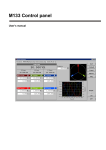
M133 control panel (freeware)
15. 3.2011
Mode
GndU
GndI
Sense
Coil
Sync
On
On
2W
Off
Int
Caliber Software for automatic calibration of instruments
Determination
The CALIBER program is intended for
automatic calibrations of instruments.
Except of the unit under test and
the standard unit, a computer with
Windows 2000/XP/Vista/7 Operating
System is being necessary. Output of
the CALIBER program represents a
physically performed calibration
with a calibration record – a table
with measured and evaluated
values (the test report).
Typical workplace
Standard instruments controlled
by the Caliber software
Basic features
••
••
••
••
••
••
••
••
••
Easy creation of calibration procedures using Procedure wizard
Automatic calibration of instruments
Instruments control via RS232, IEEE488, USB, RS485, Ethernet (VISA)
Suitable for various instruments (meters, sources, transducers)
Calculated deviation and uncertainty in each point of test report
Selectable rounding of measured and evaluated values
Calibration uncertainty evaluated according to metrology standards
Up to 20 instruments in one calibration point
Windows 2000/XP/Vista/7 (32/64 bit)
UUT (Unit Under Test)
Standard (multifunction calibrator)
Instruments prepared for
calibration
“Standard unit” and “Units
under test”
MEATEST, spol. s r. o., Zelezna 3, CZ - 619 00 Brno, Czech Republic | tel. +420 543 250 886, 887 | fax +420 543 250 890 | e-mail: [email protected] | www.meatest.com, www.meatest.cz
Caliber/1
Program window description
Instruments scheme
Instruments used in selected
calibration point and their
configuration
User prompt window
Program messages
Information line
Description of performed
operation
Set function and range manually
M3800 Function VDC-2W Range 20 V
Camera
Optional camera module
for digital display scanning
Status window
Functions
Ranges
Points
Active terminals
connection
Exceptions
Direct keys
New / Open /Save
Reload Start
Calibration
Import / Export
Test report
Measured and evaluated values (measured deviation, maximum allowed deviation, measurement uncertainty)
Values are added during the calibration.
Readings
Particular
measured
values
Function| Range|
Standard |
UUT| Deviation|%spe|
Allowed | Uncert.|
----------------------------------------------------------------------------------------------------------------------------------------------- VDC-2W| 200 mV|
20.0 mV|
20.0 mV|
-0 uV|
0|
200 uV|
62 uV| ok
VDC-2W| 200 mV|
180.0 mV| 180.6 mV|
620 uV| 62|
1003 uV|
71 uV| ok
VDC-2W| 200 mV|
-180.0 mV| -180.7 mV|
-690 uV| -69|
1003 uV|
69 uV| ok
VDC-2W|
2 V|
0.200 V|
0.200 V| -0.00 mV|
0|
2.00 mV| 0.58 mV| ok
VDC-2W|
2 V|
1.800 V|
1.807 V|
7.00 mV| 70|
10.04 mV| 0.58 mV| ok
VDC-2W|
2 V|
-1.800 V|
-1.807 V| -6.80 mV| -68|
10.03 mV| 0.64 mV| ok
…
Instruments scheme
Program uses special symbols for displaying different types of instruments in the “Instruments scheme” diagram. Up to 20 instruments can
be used in one calibration point.
1
2
1
M140
Manual
M3800
Camera
2
1
10MOHM
Manual
4
DAT1281
GPIB23
3
5
3
Caliber/2
6
4
1. Source
2. UUT (meter)
3. Standard converter
4. Standard (meter)
5. Master signal bus
6. Transformed bus
Remote control
The instruments can be operated either manually or
automatically (by computer). In automatic mode the interface
RS232 or GPIB can be used, eventually any other interfaces (USB,
Ethernet, RS485, …) which utilize the industry VISA standard.
Caliber output
Output of the CALIBER program represents a physically
performed calibration with a calibration record – a table with
measured and evaluated data (the test report).
Calibration procedure
Automatic calibration of UUTs is controlled through Calibration
procedure. Calibration procedure is list of calibration points in that
order, how they will be executed during calibration. Calibration
procedure is different for different types of UUT. Calibration
procedures for various UUT can be created direct in CALIBER
program. For running, creating and modifying of calibration
procedures, program module “Procedures” is aimed. Calibration
procedure can be prepared in program CALIBER only.
Procedure wizard
Procedure wizard serves for convenient and easy preparing
of new Calibration procedures. In general, “Instrument cards”
determines action of the instruments which are connected
to the calibration system. “Calibration procedures” define
procedure of the calibration, point by point. All basic program
modules are created in interactive way. Its generation doesn’t
require knowledge of programming.
Instrument card
Instrument card contains description of metrological features of
an instrument (functions, ranges, specification etc.) and way of
instrument control (GPIB, RS232 or VISA remote control commands).
Instrument without instrument card can’t be used in calibration
procedure. For creating and editing of instrument cards program
module “Instrument card” is prepared.
WinQbase-Caliber
Caliber can be used either independently or as a part of database
software package WinQbase. WinQbase is program for keeping
records of various types of measuring instruments. It can be used
as a program superstructure of the Caliber system. It provides
identification of measuring instruments, of calibration sheets,
record print, measuring instrument selection according to diverse
criteria etc.
Caliber program is specialized for automatic calibration of
instruments. Standard delivery contains functions for electrical
quantity meters calibration. New functions for non-electric
quantities can be defined by user and appropriate calibration
procedures can be generated.
MEATEST, spol. s r. o., Zelezna 3, CZ - 619 00 Brno, Czech Republic | tel. +420 543 250 886, 887 | fax +420 543 250 890 | e-mail: [email protected] | www.meatest.com, www.meatest.cz
Caliber/3
CamOCR (optional Camera module)
CamOcr camera module extends possibilities of MEATEST automatic calibration software Caliber. CamOcr is designed for scanning
of 7 segment digital displays.
Instruments (UUT) without remote control interface can be “connected” using CamOcr to the computer. Instrument’s display is scanned
by digital video camera. CamOcr converts scanned pictures into numbers. These numbers (measuring results) are used in for further
calculations. It is very easy to do repeated measurements and calculate uncertainty type “A” for every calibration point.
Instruments scheme
Instruments used in selected
calibration point and their
configuration
Status window
Instrument’s
connection –
used terminals
Caliber/4
Information line
Description of performed
operation
Camera
Real view from
camera
Readings
Readings
Values read
by camera
M63x / M64x
Resistance Decades and RTD Simulators
•
•
•
•
•
Resistance range up to 100 mΩ – 20 MΩ
Operating voltage 200 V
Simulation of RTD temperature sensors
User defined curves (conversion tables)
Fully programmable via RS232
(optionally USB, IEEE488, LAN)
M632
Usage
M632
M642
M631
M641
Resistance Decade
RTD Simulator
Range
Resolution
Max. load
1 Ω – 1.2 MΩ
0.1 Ω – 20 MΩ
16 Ω – 400 kΩ
10 Ω – 300 kΩ
10 µΩ
1 µΩ
0.001 °C
0.01 °C
0.25 W
5W
0.25 W
5W
Interfaces
(RS232 std.)
Accuracy
USB, GPIB, LAN
0.003 %
0.02 %
0.01°C
0.1°C
The new M6xx series programmable resistance decades and RTD simulators offer an exceptional accuracy, resolution and stability of real
resistance simulation. Both M63x decades contain stable foil resistors with low temperature coefficient switched by low thermal voltage
relays. Built-in software has also a function of RTD temperature sensor simulation with parameters according to IEC (DIN) or US standards
and temperature setting in degree of Celsius or Fahrenheit. Instrument can be controlled via RS232, USB, LAN or GPIB interface.
M6xx series programmable decades are sophisticated instruments with their own recalibration procedures. The procedure lets the user to
correct any deviation in resistance without any mechanical adjusting.
Decade box is designed for checking parameters of resistance meters, regulators and process meters that use external resistance sensors for
non-electric quantity measuring.
Specification
M632 Resistance accuracy
Range / Resolution
1.000 00 Ω – 2.000 00 Ω
2.000 1 Ω – 20.000 0 Ω
20.001 Ω – 200.000 Ω
200.01 Ω – 2000.00 Ω
2.000 1 kΩ – 20.000 0 kΩ
20.001 kΩ – 200.000 kΩ
200.01 kΩ – 1200.00 kΩ
M631 Resistance accuracy
Accuracy
0.002 % + 2 mΩ
0.003 %
0.005 %
M642 Resistance accuracy
Range / Resolution
100.000 mΩ – 200.000 mΩ
200.01 mΩ – 2.00000 Ω
2.0001 Ω – 20.0000 Ω
20.001 Ω – 200.000 Ω
200.01 Ω – 2000.00 Ω
2.0001 kΩ – 20.0000 kΩ
20.001 kΩ – 200.000 kΩ
0.20001 MΩ – 2.00000 MΩ
2.0001 MΩ – 20.0000 MΩ
Range / Resolution
16.000 0 Ω – 20.000 0 Ω
20.001 Ω – 200.000 Ω
200.01 Ω – 1000.00 Ω
1000.1 Ω – 3000.0 Ω
3001 Ω – 10000 Ω
10.01 kΩ – 30.00 kΩ
30.1 kΩ – 100.0 kΩ
101 kΩ – 400 kΩ
Accuracy
0.002 % + 2 mΩ
0.003 %
0.005 %
0.015 %
0.03 %
0.1 %
0.4 %
M641 Resistance accuracy
Accuracy
0.05 % + 15 mΩ
0.02 %
Range / Resolution
10.000 0 Ω – 20.000 0 Ω
20.001 Ω – 200.000 Ω
200.01 Ω – 1000.00 Ω
1.0001 kΩ – 3.0000 kΩ
3.001 kΩ – 10.000 kΩ
10.01 kΩ – 30.00 kΩ
30.1 kΩ – 100.0 kΩ
101 kΩ – 300 kΩ
Accuracy
0.05 % + 15 mΩ
0.02 %
0.05 %
0.1 %
0.5 %
0.05 %
MEATEST, spol. s r. o., Zelezna 3, CZ - 619 00 Brno, Czech Republic | tel. +420 543 250 886, 887 | fax +420 543 250 890 | e-mail: [email protected] | www.meatest.com, www.meatest.cz
M63x, M64x /1
Application of M630 series
M600 Series Programmable Resistance Decades
and RTD Simulators
Thermometer calibration
Ohmmeter calibration
4 W connection, accuracy 0.01 °C,
remote control
4W connection, accuracy
30ppm, remote control
Checking of meters (evaluation units) connected to resistance based sensors:
Application of M630 series
Calibration of heat meters using
two M631 RTD simulators
1
2
RTD simulators here simulate the temperatures
of input and output water of the system.
M63x, M64x /2
•
•
•
•
position sensors
rotary sensors
temperature sensors
heat meters
M63x Pt simulation accuracy
M632
Temperature
-200.000… 0.000 °C
M631
Pt10 … Pt99
0.05 °C
Pt100 … Pt20000
0.01 °C
Pt100 … Pt500
0.01 °C
Pt501… Pt1000
0.01 °C
0.001… 200.000 °C
0.06 °C
0.015 °C
0.015 °C
0.02 °C
200.001… 500.000 °C
0.08 °C
0.03 °C
0.03 °C
0.04 °C
500.001… 850.000 °C
0.1 °C
0.04 °C
0.04 °C
0.1 °C
-200.00 … 0.000 °C
Pt10 … Pt99
0.5 °C
Pt100 … Pt20000
0.15 °C
Pt100 … Pt1000
0.15 °C
-0.001 … 850.000 °C
1.0 °C
0.2 °C
0.2 °C
M64x Pt simulation accuracy
M642
Temperature
M641
M63x Ni simulation accuracy
M632
Temperature
M631
-60.000… 0.000 °C
Ni10 … Ni99
0.05 °C
Ni100 … Ni20000
0.01 °C
Ni100 … Ni500
0.01 °C
Ni501… Ni1000
0.01 °C
0.001… 300.000 °C
0.05 °C
0.01 °C
0.01 °C
0.02 °C
M64x Ni simulation accuracy
M642
Temperature
Ni10 … Ni99
0.4 °C
-60.000…300.000 °C
M641
Ni100 … Ni20000
0.1 °C
Ni100 … Ni1000
0.1 °C
M63x Frequency response
M632
M631
AC/DC
difference
1Ω
10 Ω
100 Ω
1 kΩ
10 kΩ
100 kΩ
1 MΩ
16 Ω
100 Ω
1 kΩ
10 kΩ
100 kΩ
100 Hz
0.01 %
0.01 %
0.01 %
0.01 %
0.01 %
0.1 %
2%
0.01 %
0.01 %
0.01 %
0.01 %
0.2 %
1 kHz
0.02 %
0.01 %
0.01 %
0.01 %
0.03 %
1%
0.01 %
0.01 %
0.01 %
0.03 %
1%
10 kHz
0.2 %
0.03 %
0.01 %
0.1 %
1%
0.03 %
0.01 %
0.03 %
1%
M64x Frequency response
AC/DC
difference 100 mΩ
M642
1Ω
M641
10 Ω
100 Ω
1 kΩ
10 kΩ
100 kΩ
1 MΩ
10 MΩ
10 Ω
100 Ω
1 kΩ
10 %
0.01 %
0.01 %
0.01 %
0.01 %
0.05 %
0.02 %
100 Hz
0.05 %
0.02 %
0.01 %
0.01 %
0.01 %
0.02 %
0.02 %
0.1 %
1 kHz
0.2 %
0.1 %
0.02 %
0.01 %
0.01 %
0.1 %
0.1 %
10 %
10 kHz
5%
0.5 %
0.1 %
0.03 %
0.03 %
2.0 %
10 %
MEATEST, spol. s r. o., Zelezna 3, CZ - 619 00 Brno, Czech Republic | tel. +420 543 250 886, 887 | fax +420 543 250 890 | e-mail: [email protected] | www.meatest.com, www.meatest.cz
10 kΩ
100 kΩ
0.01 %
0.01 %
0.01 %
0.01 %
0.02 %
0.10 %
0.02 %
0.5 %
10 %
M63x, M64x /3
General specification
Maximal voltage:
Maximal current:
Total power dissipation:
Temperature coefficient:
Reaction time:
Switching method:
Terminals:
Remote control:
Power supply:
Reference temperatures:
Working temperatures:
Storage temperatures:
Dimensions:
Weight:
200 V pk
500 mA
0.25 W (M63x)
5 W (M64x)
10 % of specification per °C outside
the reference temp. range
6 ms
Fast / Smooth / Via short / Via open
gold plated terminals 4 mm
RS232 interface (optionally USB,
LAN, IEEE488)
115/230 VAC, 50/60 Hz
+20 °C … +26 °C
+5 °C … +40 °C
-10 °C … +50 °C
W 390 mm, H 128 mm, D 310 mm
5.2 kg (M63x)
4.0 kg (M64x)
Basic accessory (included)
Cable RS 232
Application software
User’s manual
Options (extra ordered)
Bus
M6xx-V1xxx – RS232
M6xx-V2xxx – RS232, USB, LAN, GPIB
Housing
M6xx-Vxx0x – table version
M6xx-Vxx1x – module 19", 3HE
M642
Design for industry
– 19" rack module,
height 3HE
Resistance
Temperature
Recalibration
M63x, M64x /4
M-109R High Resistance Decade
•• Calibration of insulation meters
and megaohmmeters
•• 4 decades
•• Range 1 MOhm – 12 GOhm
•• Maximum working voltage 5 kV
•• Internal battery or power
line adapter supplying
•• RS 232 control
M-109R
High resistance decade box is designed for calibrating of insulation meters and megaohmmeters. It is suitable for calibration laboratories
and service centres, where can be used also for testing or setting of high resistance meters. High voltage relays with extremely high
insulation resistance are used for switching of resistance components.
M-109R is equipped with indication of input terminal overload. Instrument is supplied from accumulator or power line adapter.
Control is possible manually or remotely via serial interface RS-232.
Specification
Range of resistance:
Maximum voltage:
Connection: Type of terminals: Remote control:
Supply:
Temperature range:
Relative humidity:
Dimensions:
Weight:
1 MΩ - 12.221 GΩ
5kV DC between terminals H-L, H-GND, L-GND
two-terminal, three-terminal (GUARD)
high voltage terminals with ERTALYTE isolation
serial interface RS-232
internal accumulator, power line supply adapter 15 V (100-240 V/50-60 Hz)
23 °C ± 5 °C
10 - 50 %
364 mm x 111 mm x 316 mm
4 kg
Accuracy
Decade
Nominal value accuracy
Voltage coefficient
Temperature coefficient
Maximum voltage
1 MΩ - 11 MΩ
10 MΩ - 110MΩ
100 MΩ - 1.1 GΩ
1 GΩ - 12 GΩ
[%]
0.1
0.2
0.5
1.0
[ ± ppm/V ]
1
1
2
2
[ ± ppm/ °C ]
< 100
< 100
< 100
< 100
[ VDC/RMS ]
1000/700
2500/1700
5000/3500
5000/3500
Basic accessory (included)
Options (extra ordered)
Power line adapter
Cable RS-232
CD with application software
User’s manual
Test report
Test lead 5000 VDC / 20 A
MEATEST, spol. s r. o., Zelezna 3, CZ - 619 00 Brno, Czech Republic | tel. +420 543 250 886, 887 | fax +420 543 250 890 | e-mail: [email protected] | www.meatest.com, www.meatest.cz
M-109R/1
Front panel
Output teminals
2W resistance
LED indicated
maximum input voltage
GND terminal
protection earth
LED indicated
switching the decade on
Individual
rotary buttons
LED indicated
mod of remote control
Application
Calibration and verification of meters with test voltage up to 5 kVDC:
-
-
-
-
Insulation testers
Safety testers
Megaohmmeters
Ohmmeters
LED Indicated
maximum input voltage
LED indicated
switching the decade on
M-109R/2
1. Press ON/OFF button
2. Set requested value using
individual rotary buttons
M191
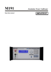
Insulation Tester Calibrator
M191
• Programmable high voltage high resistance
decade box
• Resistance range from 10 kΩ to 1 TΩ
• Operating voltage range up to 10 kVDC
• Grounded or floating operation
• Built-in three fix value high voltage capacitors
from 10 nF to 100 nF
• Built-in monitoring voltmeter
• SHORT function for short current testing of UUTs
• Timer function for testing of UUTs
• Easy recalibration using front panel keypad
• GPIB & RS232 interface
M191 calibrator is based on programmable high resistance decade with additional electronic circuits allowing calibration of not only
resistance ranges, but also calibration of UUT test voltage, short current testing, verifying of functions of measuring dielectric parameters
like polarization index (PI), dielectric absorption ratio (DAR) and polarization ratio (PR). The calibrator can be also used to verify timer
function of the UUT.
Main feature of the calibrator is High resistance source mode. In this mode any resistance value in range from 10 kΩ to 1 TΩ adjustable with
4 digit resolution can be set and connected to the output terminals. Maximum allowed working DC voltage is from range 50 V to 10 000 V
depending on set resistance. Switching the resistance value under test voltage is allowed in limited voltage range. In this range it the basic
accuracy is 0.1 % to 5 % depending on set resistance value.
The calibration can be controlled manually using front panel keypad or in remote mode using one of two types of interfaces GPIB, RS-232.
The calibrator can easily fit within calibration systems featuring CALIBER software support.
Specification
Function HVR (High resistance programmable decade box)
Total resistance range:
Test voltage range:
Maximum applicable voltage during over-switching:
Test voltage indication:
Test voltage accuracy:
Test current indication:
Maximum safe DC voltage between H and L terminal:
Maximum allowed DC voltage between L and GND terminal:
10.00 kΩ to 1000.0 GΩ
10 000 VDC + 5 % over range
3 000 VDC (without output terminals disconnection)
4 digit meter with range of 10 kVDC with suppressed
indication below 50 VDC
0.5 % + 10 V
4 digit meter in range from 0.01 pA to 99.99 mADC
11 000 VDC
15 VDC
MEATEST, spol. s r. o., Zelezna 3, CZ - 619 00 Brno, Czech Republic | tel. +420 543 250 886, 887 | fax +420 543 250 890 | e-mail: [email protected] | www.meatest.com, www.meatest.cz
M191/1
Accuracy in grounded mode (G) and floating mode (F):
Resistance range
Accuracy in
G mode*
Accuracy in
F mode*
Maximum DC test
voltage***
0.2 %
0.2 %
0.1 %
0.1 %
65 V
315 V
1 250 V
5 000 V
0.2 %
0.2 %
0.5 %
0.5 %
1.0 %
2%
3%
6%
10.00 kΩ – 99.99 kΩ
100.0 kΩ – 999.9 kΩ
1.000 MΩ – 9.999 MΩ
10.00 MΩ – 99.99 MΩ
100.0 MΩ – 499.9 MΩ
500.0 MΩ – 999.9 MΩ
1.000 GΩ – 9.999 GΩ
10.00 GΩ – 19.99 GΩ
20.00 GΩ – 99.99 GΩ
100.0 GΩ – 299.9 GΩ
299.9 GΩ – 1000.0 GΩ
* ** ***
1%
2%
5%
Typical voltage
dependency
< 0.05 ppm/V
< 0.07 ppm/V
10 000 V
Test voltage
accuracy
0.5 % + 10 V
< 0.15 ppm/V
< 0.20 ppm/V
N/A**
Test current range
Test current
accuracy
10 mA
2.5 mA
1 mA
500 μA
100 μA
20 μA
10 μA
1 μA
500 nA
100 nA
N/A**
0.7 % + 100 μA
0.7 % + 10 μA
0.7 % + 1 μA
0.7 % + 100 nA
0.7 % + 20 nA
1 % + 10 nA
1.5 % + 1 nA
1.5 % + 500 pA
2 % + 100 pA
5 % + 20 pA
N/A**
Accuracy is valid in reference temperature range 23+/-2 °C with RH < 50 %.
Test voltage voltmeter function is not available in resistance range from 299.9 GΩ to 1 000 GΩ.
Maximum measured DC test voltage is 5 % over the specified range
SHORT function for Short test current verification
Current range:
Input resistance:
Short test current accuracy:
0.000 – 5.000 mA DC
2700 Ω nom.
0.2 % + 5 uA
HVC function, high voltage capacitance
Range of capacitance:
Tolerance:
Calibration value uncertainty:
Max. test voltage:
Test voltage indication:
Test voltage accuracy:
10, 50, 100 nF fix values
± 10 %
0.3 % + 200 pF
5 000 VDC + 5 % over range
0 to 5 000 kVDC with suppressed indication bellow 50 VDC
0.5 % + 10 V
General specification
Warm up time:
Operating temperature: Reference temperature:
Temperature coefficient:
Humidity coefficient: Storage temperatures:
Dimension:
Netto weight
Power line:
Power consumption: 15 minutes
23 ± 10 ºC, Relative humidity < 70 %
23 ± 2 ºC, Relative humidity < 50 % for resistance range from 10 kΩ to 1 000 GΩ
Relative humidity < 70 % for resistance range from 10 kΩ to 10 GΩ
Additional resistance uncertainty due to temperature coefficient for temperature
outside of Tcal ± 2 °C:
from + 13 °C to +33 °C add 0.1 x specified accuracy / °C at reference temperature
Additional uncertainty due to humidity coefficient in range 50 to 70 % RH is:
- 0.15 x specified accuracy / % RH for range 10.00 GΩ to 1 000.0 GΩ
- 0.05 x specified accuracy / % RH for range 100.0 MΩ to 9.99 GΩ
- 0.02 x specified accuracy / % RH for range 10.00 kΩ to 99.99 MΩ
-10 ºC … + 55 ºC
W 450 mm, H 150 mm, D 430 mm
12 kg
115/230 VAC, 50/60 Hz
40 VA
Following information is displayed on the display:
- Set resistance value in Ω.
- Maximum safe test voltage that can be applied to the output
terminals.
- Actual test voltage. This is value of DC test voltage sourced
by UUT and connected to the calibrator output terminals.
- Test current.
- Accuracy. Selected resistance point accuracy shown in %.
M191/2
M-192/192A
Programmable AC/DC Load
High Power Programmable Resistance Decade Box
3000 W
••
••
••
••
Resistance range 15 Ω to 300 kΩ
Maximal load 3 kW
Maximal voltage 250 V RMS
Accuracy 0.1 %
••
••
••
••
Temperature coefficient < 10 ppm/°C
2, 4 – wire connection
Interface RS – 232 (IEEE488 optionally)
Table version (19“ module as option)
M-192 AC/DC load is determined for testing voltage sources, transformers or generally as power load up to 3 kW. Load is especially suitable
for automated testing systems.
Thanks to good accuracy and remote control feature M-192 load can be used in calibration laboratories, production lines, service centers
and development departments. For use in industry is designed version in 19“ module with height 4 HE.
Among advantages belongs features like simple control from the front panel, indication of set-up values on LCD display, resistance, power
and current modes, remote control via RS-232 or IEEE488 bus.
Specification
Resistance range
Resolution
Temperature coefficient
Maximal dissipation power
Maximal voltage
Internal voltmeter (M-192A only)
Connection
Range of reference temperatures
Range of operating temperatures
Storing temperatures
Housing
Dimensions and weight Isolation resistance between signal outputs and housing 15 Ω - 4700 Ω / 15 Ω - 300 kΩ (version M-192A)
0.1 Ω to 1 Ω for M-192 version, 0.001 Ω to 1 kΩ for M-192A version
< 10 ppm/°C
3000 W
250 V RMS
range 300V AC/DC, AC/DC automatic selection, resolution 0.1 V
2, 4 wires
+18 °C … +28 °C
+5 °C … +45 °C
-10 °C … +60 °C
metal
W 460 mm, H 190 mm, D 440 mm (without holders), 15 kg
> 2 GΩ (at 1000 Vdc)
Content of delivery
Versions
M-192/192A Programmable AC/DC Load
Operation manual
Power cable
Test report
Interface
M192-V1xxx - RS232
M192-V2xxx – IEEE488
Housing
M192-Vxx0x – table version
M192-Vxx1x - module 19“, 4 HE
MEATEST, spol. s r. o., Zelezna 3, CZ - 619 00 Brno, Czech Republic | tel. +420 543 250 886, 887 | fax +420 543 250 890 | e-mail: [email protected] | www.meatest.com, www.meatest.cz
M192/1
Resistance accuracy (M-192 only up to 4700 Ω)
Range
Internal voltmeter (M-192A only)
Range
Accuracy
15.000 Ω - 99.999 Ω
100.000 Ω - 3.000 kΩ
3.001 kΩ - 30.00 kΩ
30.1 kΩ - 100.0 kΩ
101 kΩ - 300 kΩ
DC…120Hz
0.1 % + 30 mΩ
0.1 %
0.1 %
0.2 %
0.5 %
120Hz…1kHz
0.2 % + 30 mΩ
0.1 %
0.1 %
0.2 %
2,00%
1kHz…10kHz
0.2 % + 30 mΩ
0.2 %
2,00%
—
—
Accuracy
DC
0.1 % + 0.2 V
1.0 - 299.9 V
AC
0.2 % + 0.2 V
Typical frequency response (M-192A)
Rnom
15 Ω
100 Ω
330 Ω
1000 Ω
10 kΩ
100 kΩ
Z [Ω]
Ø [°]
Z [Ω]
Ø [°]
Z [Ω]
Ø [°]
Z [Ω]
Ø [°]
Z [kΩ]
Ø [°]
Z [kΩ]
Ø [°]
100Hz
1kHz
10kHz
100kHz
1MHz
15
0
100
0
330
0
1000
0
10
-0,02
100
-0,18
15
0,03
100,01
0,01
330,02
0
1000
-0,02
10
-0,23
99,78
-2,3
15
0,26
100,02
0,08
330,03
0,01
999,9
-0,18
9,97
-2,2
91,7
-20,5
15,03
2,4
99,97
0,75
329,73
0,08
997
-1,7
9,21
-19
27
-70,4
15,15
23
91,5
9,1
301,3
4,1
854
-9
3,15
-57
N.A.
Application
Battery testing
Load display R mode
Output terminals
2 W/ 4 W
U
15.206 Ω
0.0 V
Battery charger
testing
AC/DC Supply
sources testing
1. Set requested value using
numerical keypad or kursor
keys
2. Press ENTER
3. Press ON/OFF
Amplifier testing
Transformer testing
M192/2
M550
Impedance Calibrator
M550
• Calibration of LCR meters
• Applicable frequency range up to 1 MHz
• Resistance range 100 mΩ to 100 MΩ
• Interface RS232 & IEEE488
• Capacitance range 10 pF to 100 µF
• Simulated inductance standards 10 µH to 10 H
• Four pair coaxial terminal connection, four
terminal connection, two terminal connection
• Best calibration uncertainty 0.02 % at 1 kHz
• OPEN and SHORT reference functions
Model M550 Impedance calibrator is designed for calibration of LCR meters. The calibrator consists of several banks of resistance,
capacitance and inductance standards of fix decimal values. Total range cover values from 0.1 Ω to 100 MΩ, 10 pF to 100 μF and
10 μH to 10 H. Calibrator has four-pair terminal and four terminal coaxial output connectors for calibration of precise and wide
range LCR meters, four-terminal and two-terminal non-coaxial output connectors for calibration of simple LCR meters and older
LCR meters.
Basic applicable frequency range is from 20 Hz to 1 MHz in coaxial mode and up to 100 kHz in non-coaxial mode.
Calibration memory stores both real and complex parameters of all partial standards. Calibration values can be displayed in wide
range of frequently used pairs of complex impedance and admittance. Either parallel or series equivalent model can be selected.
The calibrator is equipped with reference positions OPEN and SHORT terminals to eliminate test cable influence.
Built-in level meter of voltage and frequency of LCR meter test signal comes as standard. M550 is compatible with Meatest
automation software CALIBER.
MEATEST, spol. s r. o., Zelezna 3, CZ - 619 00 Brno, Czech Republic | tel. +420 543 250 886, 887 | fax +420 543 250 890 | e-mail: [email protected] | www.meatest.com, www.meatest.cz
M550/1
Specification
Modes:
Output terminals:
Frequency range:
Reference correction positions:
4TP four pair terminal, 4 W four terminal, 2 W two terminal
4x BNC connectors for coaxial output (4TP)
4x banana terminal for non-coaxial output (2 W/4 W)
20 Hz to 1 MHz
SHORT, OPEN
Resistance
Inductance (simulated in 4TP mode only)
Range:
Deviation to nominal value:
Calibration uncertainty:
Temperature coefficient:
0.1 Ω to 100 MΩ (fix decimal values)
0.10 % to 10 % depending on value
and mode
0.02 % to 1 % at 1 kHz depending
on value and mode
2 to 25 ppm/ °C
Capacitance
Range:
Deviation to nominal value:
Calibration uncertainty:
Temperature coefficient:
10 µH to 10 H (fix decimal values)
< 15 %
0.1 % to 4 % at 1 kHz depending
on value and mode
50 ppm/ °C max.
Test level meter
Range:
Deviation to nominal value:
Calibration uncertainty:
Temperature coefficient:
10 pF to 100 µF (fix decimal values)
<5%
0.05 % to 5 % at 1 kHz depending
on value and mode
30 to 100 ppm/ °C
Frequency range:
Voltage range:
Test voltage accuracy:
20 Hz to 100 kHz
200 mV to 10 V rms
2 to 5 %
General data
Interface:
Operating temperature:
Storage temperature:
Dimension:
Net weight:
Power line:
Consumption:
RS232, GPIB
15 … 30 °C
-10 … +40 °C
W 450 mm, H 150 mm, D 430 mm
12 kg
115/230 VAC, 50/60 Hz
45 VA
Automation of LCR meter calibration
M550 Impedance calibrator application combines precise and frequency independent partial standards of electric resistance, capacitance
and inductance in one instrument. Both manual and remote control is available making the M550 an effective tool for manual or automatic
adjustments, verifications and calibrations of various types of LCR meters. In 4TP mode the calibrator enables verification of LCR meter in
frequency range up to 1 MHz. Calibration values either with or without test cable length correction are selectable.
Recalibration procedure
M550 calibration menu offers comfortable recalibration of calibration data. Two basic methods are implemented to make the recalibration
easier. Full recalibration enables access to all stored complex calibration values of all partial standards in spot frequencies. Modification
of frequency characteristics is fully accessible in this method. Offset recalibration simplifies the process of recalibration to modification of
main parameter at 1 kHz only. Difference from the previous calibration value is automatically projected to all spot frequencies.
Basic mode display
Calibration menu display
Calibration values
Calibration uncertainty
Test level meter reading
M550/2
MTE LF Resistance/Capacitance/Inductance Standards
••
••
••
••
••
MTE
Traceability of electric quantities
Calibration of meters
Calibration uncertainty 0.005 %
Low time constant
Three/four terminal or four pair terminal
connection
Resistance/Capacitance standards of series MTE are designed for calibration of ohmmeters, RCL meters, insulation testers calibration. They
can be applied as a mean of traceability of electric resistance between primary and secondary laboratories.
DC modification of the standards is equipped with 4 mm terminal socket. Resistance standards up to 1 MΩ are in four-terminal connection
while standards over 10 MΩ have two terminal connection with additional insulation washer and with grounding terminal connected to
the housing.
AC resistance versions and capacitance/inductance standards are delivered with four BNC connectors enabling application in threeterminal, four-terminal, four-pair terminal configuration. As a part of MTE set for AC applications the reference positions OPEN and SHORT
terminals can be delivered. Both components serve typically for zero calibration of RCL meters.
Other type of connectors can be installed on request. Other nominal values can be delivered on request.
LF Capacitance standards MTE series
Connection
Type of terminals
Frequency range
Model
Four pair terminal
BNC coaxial connectors for AC applications
20 Hz - 20 kHz to 1 nF, 20 Hz – 10 kHz to 100 uF
Nominal value
Accuracy
1 kHz calibration
uncertainty
Temperature
coefficient
Dissipation factor
Note
[%]
[%]
[ ± ppm / °C ]
[-]
Type
Ceramic multilayer
Silver mica
Ceramic multilayer
Silver mica
Silver mica
Silver mica
Silver mica
Polypropylen
Polypropylen
Polypropylen
CP – 10p
10 pF
1
0.01
15
≤ 0.001
CP – 100p
1 00 pF
0.1
0.01
15
≤ 0.001
CP – 1n
CP – 10n
CP – 100n
CP – 1u
CP – 10u
CP – 100u
1 000 pF
10 000 pF
100 000 pF
1 uF
10 uF
100 uF
0.1
0.1
0.1
0.1
0.2
0.2
0.01
0.01
0.01
0.01
0.1
0.1
15
15
15
50
50
50
≤ 0.0005
≤ 0.0005
≤ 0.0005
≤ 0.0005
≤ 0.005
≤ 0.005
MEATEST, spol. s r. o., Zelezna 3, CZ - 619 00 Brno, Czech Republic | tel. +420 543 250 886, 887 | fax +420 543 250 890 | e-mail: [email protected] | www.meatest.com, www.meatest.cz
MTE/1
LF Inductance standards MTE series
Connection
Type of terminals
Frequency range
Four pair terminal
BNC coaxial connectors
100 Hz – 20 kHz
Model
Nominal value
Accuracy
1 kHz calibration
uncertainty
Temperature
coefficient
Min. quality factor
for f=1 kHz
Note
LP – 100m *
LP – 1**
LP – 10
LP – 100
LP – 1000
100 mH
1H
10 H
100 H
1000 H
[%]
0.5
0.5
0.5
0.5
0.5
[%]
0.05
0.05
0.05
0.05
0.05
[ ± ppm / °C ]
50
50
50
50
50
[-]
≥ 3 ***
≥3
≥ 10
≥ 10
≥ 10
Type
T-network
T-network
T-network
T-network
T-network
T network is composed from two resistors and one capacitor. The network can simulate inductance parameter L21 with Q factor over 3 in recommended frequency area.
The standard can be applied for calibration of those RCL meters which measure test current in Low input terminal. The standard cannot be applied for calibration of classic transformer bridges.
*
Applicable frequency range from 10 to 20 kHz; * * Applicable frequency range from 1 kHz to 20 kHz; * * *
Q factor for frequency 10 kHz
LF Resistance standards MTE series
Connection
3-terminals (above 10 MΩ), 4-terminals or 4 pair-terminals (bellow 10 MΩ)
Housing
type MTE1 for general application with BNC terminals or gold plated terminals
Dimensions 125 x 60 x 105 mm
M-530
for RCL meter calibration designed for direct connection to the front panel
connectors with two fixing female BNC screws
Dimensions 105 x 33 x33 mm
Type of terminals
BNC coaxial connectors for AC applications (0.1 Ω to 10 MΩ)
Gold plated terminals for DC applications (0.1 Ω to 10 MΩ)
Standard terminals with additional ertallyte isolation (above 10 MΩ)
Frequency range
*
DC to 20 kHz for nominal value 0.1 Ω to 10 MΩ (with BNC connectors)
Model
Nominal Value
Accuracy
DC calibration
uncertainty
Temperature
coefficient *
Power rating **
Note
RP – 0.1
RP – 1.0
RP – 1.0
RP – 10
RP – 100
RP – 1k
RP – 10k
RP – 100k
RP – 1M
RP – 10M
RP – 100M
RP – 1G
RP – 10G
100 mΩ
1Ω
1Ω
10 Ω
100 Ω
1 kΩ
10 kΩ
100 kΩ
1 MΩ
10MΩ
100 MΩ
1 GΩ
10 GΩ
[%]
0.1
0.05
0.05
0.01
0.01
0.01
0.01
0.01
0.01
0.05
0.5
1
3
[%]
0.05
0.01
0.01
0.005
0.005
0.005
0.005
0.005
0.005
0.01
0.1
0.3
0.5
[ ± ppm / °C ]
10
10
1
1
1
1
1
1
1
100
100
100
100
[W]
3
3
3
0.3
0.3
0.3
50 V ***
150 V ***
500 V ***
2 500 V***
2 500 V***
5 000 V***
5 000 V***
Resistance segment
Foil resistor
Foil resistor
Foil resistor
Foil resistor
Foil resistor
Foil resistor
Foil resistor
Foil resistor
Foil resistor
Ceramic resistor
Ceramic resistor
Ceramic resistor
Ceramic resistor
in temperature range 0–50 °C; MTE/2
**
for ambient temperature 23 °C; ***
maximal voltage
M-530 RF Resistance/Capacitance Standards
M-530
•• Resistance range 10 Ω to 1000 Ω
•• Very low frequency dependency
•• Applicable frequency range to 100 MHz
•• Calibration of wide frequency range
LCR meters
The resistance standard set is designed especially for calibration of LCR meters in frequency range from DC to 100 MHz. The standards are
equipped with four coaxial BNC connectors. Wide frequency range is achieved by applied HF design using strip line technology. Four-pair
terminal connection with 22 mm distance between them enables direct connection to the UUTs without need to apply test leads.
The standards are available with nominal value 10, 50, 100, 500, 1000 Ω in 1% tolerance. Reference positions OPEN and SHORT for easy
“zero” compensation are available as well.
10
Frequency dependency
dR (%)
f (MHz)
0.001
0.01
0.1
1
10
100
1000
0.1
Applicable frequency range of the resistance
standards depends on nominal resistance value and
requested maximal deviation.
Typical frequency characteristics are shown in the
diagram.
1000 R
500 R
0.01
10&100 R
50 R
0.001
5
0.001
0.01
0.1
0
-5
-10
-15
Load parameters
P (mW)
10
Maximal electric power dissipated in the standards
is limited due to small size of applied resistive
segments.
Typical relative change of the resistance value when
loaded with 5 mW electric power is shown in the
graph bellow.
-20
-25
-30
dR (ppm)
-35
MEATEST, spol. s r. o., Zelezna 3, CZ - 619 00 Brno, Czech Republic | tel. +420 543 250 886, 887 | fax +420 543 250 890 | e-mail: [email protected] | www.meatest.com, www.meatest.cz
M-530/1
Time constant
Extremely low time constant of the resistance standards is given by high frequency design and RF resistance segments.
The time constant value is in order of 10 -10 to 10 -11 s.
Temperature coefficient
Typical temperature coefficient is 0.2 ppm/°C for nominal values 10, 50, 100 Ω and 15 ppm/°C for values 500 and 1000 Ω.
Technical specification
Model
Nominal value
M530–10R
M530–50R
M530–100R
M530–500R
M530–1000R
OPEN
SHORT
Ω
10
50
100
500
1000
—
0
Self-inductance: Connection:
Distance between connectors:
Dimensions:
Housing:
Range of working temperatures:
Max. deviation to Maximal frequency Maximal frequency
nominal value for 0.1% deviation for 1% deviation
%
1
1
1
1
1
—
—
MHz
2
10
2
0.5
0.1
2
2
MHz
200
> 500
200
50
10
200
200
Time constant
Temperature
coefficient
Maximal test
current
s
< 2.10–10
< 2.10–10
< 5.10–11
< 2.10–10
< 2.10–10
—
—
ppm/°C
<1
<1
<1
< 25
< 25
—
—
mA
40
20
12
6
4
—
100
< 0.08 μH
4 x BNC male connector
22 mm
105 x 34 x 50 mm (including connectors)
aluminum
15 – 30 °C
Application
Calibration of LCR metrers
The standards are equipped with BNC connectors with spacing which equells spacing of input terminals of most frequently used LCR
meters.
Calibration in this way excludes thé most significant uncertainties related to cabelling.
M-530/2
TM-185D Temperature/ Humidity Monitor
TM-185D
•• Temperature and relative humidity
measurement
•• Real time data
•• Large LED display
•• Data logging capacity 30 000 records
•• Alarm set for Hi and Low limit
Temperature and Humidity
•• USB interface
TM-185D is measuring instrument, which measures, displays and saves information about reference conditions in laboratories.
It measures ambient temperature and relative humidity. Wide time range of ambient conditions can be scanned and recorded by setting
of appropriate interval of recording. When power line supplying is interrupted, monitor operates from internal back-up source without
losing any formerly stored data.
TM-185D can be used independently or as a part of automated calibration systems. It is supported by calibration software WInQbase.
Basic delivery contains the instrument with temperature/humidity sensor, AC/DC adapter and software for transferring of measured values
to a PC. The instrument ensures the requirements of standards ISO 9000/45001, which calibration laboratory have to fulfil.
Technical parameters
Temperature
Temperature range:
Temperature accuracy:
Temperature resolution:
Update rate:
-20 … 60 °C
1 °C (in range -5 … 40 °C)
2 °C (outside the range -5 … 40 °C)
0.1 °C
1 s
Relative humidity
Humidity range:
Humidity accuracy:
Humidity resolution:
Update rate:
5 - 95 % RH
2 % (in range 25 °C, 35 … 80 % RH)
2.5 % (in range 25 °C, 10 … 35 and 80 … 90 % RH)
5 % (for 25 °C, other ranges)
0.1 %
4 s
General parameters Data logger capacity
Power supply
Interface
Size
Weight
Other functions
30000 samples
AC/DC adapter 9V/1A, backup battery 9V
USB
260 x 178 x 47 mm
1000 g
temperature and humidity alarm limits PC user software (CD ROM)
MEATEST, spol. s r. o., Zelezna 3, CZ - 619 00 Brno, Czech Republic | tel. +420 543 250 886, 887 | fax +420 543 250 890 | e-mail: [email protected] | www.meatest.com, www.meatest.cz
TM-185D/1
M-301 Precision Oil Bath
M-301
•• Capacity 55 l of oil
•• Temperature stability 0.002 °C
•• Automating mode of tempering
•• Manual operation
•• Interface bus GPIB
M-301 Precision oil bath is a device which is able to hold choice temperature of a work liquid of a total volume of 55 litres with a great
accuracy. It is especially determined for tempering standards of electric quantities, for calibrating thermometers and temperature scanning
sensors. All thermostat functions are operable on interface bus GPIB. A possibility of a system operation even enables an active control
of a temperature rise slope. The thermostat is equipped with protections which automatically disconnect all power elements in a case of
detection of any anomaly when running. It is equipped with STBY mode which enables holding of the working liquid temperature within
a selected tolerance zone even when a proper thermostating is disconnected. A DAY mode switches over the thermostat function from a
thermostating function into a STBY function at an in-advance programmed hour.
Basic temperature range of the working liquid is from Tambient – 5 °C to 55 °C..
Technical parameters
Range of reachable temperature:
Tamb – 5 to +55 °C
Cooling slope at a difference of oil
and ambient temperatures of 1 °C:
1,5 °C / hour for type
Non-homogenity of temperature field inside
working space:
0,01 °C max.
Temperature stability after setting:
0,002 °C / 5 hours
Temperature set-up resolution:
0,001 °C
Temperature adjustment accuracy of working liquid
in range ± 5 °C from calibrating point:
0,05 °C
Working space dimensions:
440 x 325 x 250 mm
Overall dimensions:
1145 x 500 x 370 mm
Power input of heating element:
350 VA
Power input of cooling elements:
150 VA for type
Power supply voltage:
220–230V / 50–60 Hz
M-301/1
M-520 Programmable Capacitance Decade
M-520
•• Designed for RCL meters calibration
•• Range from 100 pF to 12 μF
•• Basic accuracy 0.25 %
•• Maximal operating voltage 50 V
•• Power supplying from internal battery
or power line adapter
•• Remote control RS-232
Capacitance decade is designed especially for calibration of capacitance ranges of multimeters and RCL meters. Due to its versatility it can
be applied in calibration laboratories, repair centres and in production lines, where remote control of capacitance is requested. Main parts
of the M-520 decade are relays with high current capability and foil capacitors with polypropylen dielectric.
Important feature of the decade is easy recalibration capability. Process of recalibration consists of measuring of partial capacitors inside
the instrument and saving new calibration values into internal calibration memory. For recalibration purpose simple application program is
delivered with the unit.
Remote control RS-232 or USB (optional convertor).
Specification
Residual capacitance Co
Number of decades
Accuracy
Temperature coefficient
Maximal allowed voltage
Test voltage
Frequency range
Connection
Typ of terminals
Remote control
Power supply Operating period
Reference temperatures
Range of working temperatures
Range of storing temperatures
Dimensions
Weight
*
typ.< 2 pF with floating terminal L and 00000 setting
typ. < 10 pF with grounded terminal L and 00000 setting
5
2.5 % ± 1pF for decade x 100 pF
0.25 % for all others
< 250 ppm/°C (polypropylen dielectricum)
50 V DC (Imax 1.5 A), 35 V AC (Imax 1 Aeff)
500 V DC between GND and L/H terminals in floating connection
40 Hz to 1 kHz
two-terminal
instrument gold plated terminals, diameter 4 mm
interface RS-232, galvanically isolated
internal battery 12 V type LONG B-WP 1.9-12
power line adapter 15 V/1 A (100 – 240 V)
typ. 4 hours from internal battery, continuously from power line adapter
+23 °C ± 2°C
+5 °C to 40 °C
-10°C to +50 °C
W 364 mm, H 111 mm, D 316 mm
4 kg
Decade
Nominal value accuracy * [ % ]
Dissipation factor * [ - ]
Temperature coefficient
[ ppm/°C ]
100 pF – 1100 pF
1 nF – 11 nF
10 nF - 110 nF
100 nF – 1100 nF
1 uF – 11 uF
2.5 ± 1pF
0.25
0.25
0.25
0.25
< 0.05
< 0.005
< 0.005
< 0.005
< 0.05
< 250
< 250
< 250
< 250
< 250
at 1 kHz
M-520 Control Panel
Application software is delivered with every unit.
The program is designed to demonstrate capabilities
of the capacitance decade in remote mode.
Using the software any capacitance value can be set
from control computer.
MEATEST, spol. s r. o., Zelezna 3, CZ - 619 00 Brno, Czech Republic | tel. +420 543 250 886, 887 | fax +420 543 250 890 | e-mail: [email protected] | www.meatest.com, www.meatest.cz
M-520/1
M525
Programmable Capacitance Box
M525
• Designed for capacitance meters calibration
• Capacitance range 100 pF – 100.00 µF
• Capacitance accuracy 0.25 %
• Operating voltage 50 V
• User defined curves (conversion tables)
• RS232 (optionally USB, IEEE488, LAN)
Model M525 is a precise capacitance decade box with range from 100 pF to 100 µF. Basic accuracy is 0.25 %.
Best resolution on the lowest range is 1 pF. Capacitors are switched using special relays designed for high currents.
Comfortable user interface offers direct setting of capacity value, OPEN correction, grounding L terminal, user conversion
curves setting and others.
Decade can be remotely controlled by a computer using standard RS232 interface.
LAN, USB and GPIB interfaces are optional.
M525 is equipped with an internal calibration menu that allows correcting any deviation of capacity value without opening
the instrument. Decade is designed for checking multimeters and simple RLC meter.
It is suitable also for repair, adjustment and calibration of measuring instruments.
Specification
Range / Resolution
Accuracy
1 kHz
Loss coefficient
1kHz
Accuracy
40 Hz – 1 kHz
Loss coefficient
10 Hz – 1 kHz
0.100 nF – 10.000 nF
0.25 % ± 3pF
< 0.05
0.5 % ± 3pF
< 0.05
10.001 nF – 100.00 nF
100.01 nF – 1.0000 uF
0.25 %
1.0001 uF – 10.000 uF
10.001 uF – 100.00 uF
< 0.005
< 0.05
0.25 %*
< 0.2 *
< 0.005
0.5 %
Temperature
coefficient
< 270 ppm/ °C
< 0.05
< 0.2 **
Note:
* For frequency 100 Hz
** For frequency range 40 -100 Hz
Capacity value is defined in the output terminals level.
Correction Open OFF – capacity value is defined relative to the OPEN value.
Correction Open ON – capacity value is defined absolutely.
MEATEST, spol. s r. o., Zelezna 3, CZ - 619 00 Brno, Czech Republic | tel. +420 543 250 886, 887 | fax +420 543 250 890 | e-mail: [email protected] | www.meatest.com, www.meatest.cz
M525/1
General specification
Maximal voltage:
50 Vpk
Content of delivery
Temperature coefficient:
< 270 ppm/ °C
Reaction time:
< 200 ms
Reaction time TIMING :
min 500 ms
Terminals:
gold plated terminals 4 mm
Programmable Decade Box M525
Cable RS 232
Application software
User’s manual
Remote control:
RS232 interface
(optionally USB, LAN, IEEE488)
Power supply:
85-260 VAC, 45-65 Hz
Reference temperatures:
+ 21 °C … + 25 °C
Working temperatures:
+ 5 °C … + 40 °C
Storage temperatures:
- 10 °C … + 50 °C
Dimensions:
W 390 mm, H 128 mm, D 310 mm
Weight:
4 kg
Ordering information – options
Capacitance
M525-V1xxx - RS232
M525-V2xxx - RS232, USB, LAN, GPIB
Housing
M525-Vxx0x - table version
M525-Vxx1x - module 19“, 3 HE
Calibration
Function timing
M525/2
Bus
Exhibitions
MEATEST works in the field of metrology and
measuring instruments for 17 years.
MEATEST takes part in worldwide
exhibitions every year.
Seminars
MEATEST organises seminars and training courses for
customers to help them to get the most out of their
investment in calibration instruments and software.
Calibration laboratory
For testing and calibration MEATEST uses
its own calibration laboratory. Laboratory
is equipped with high precise measuring
instruments with traceability to the Czech
national standards.
Brno – town in centre of Europe
Brno – capitol of Moravia region is place of
company residence.
MEATEST facility is located close to D1 and D2
highways crossing with only
1 hour to Bratislava
1.5 hour to Vienna
2 hours to Prague
2
MEATEST, spol. s r. o.
Zelezna 3
CZ - 619 00 Brno
Czech Republic
Tel. +420 543 250 886, 887
Fax +420 543 250 890
e-mail: [email protected]
www.meatest.com
www.meatest.cz
EUROPEAN UNION
EUROPEAN REGIONAL DEVELOPMENT FUND
INVESTMENT IN YOUR FUTURE


