1
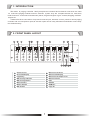
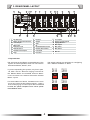
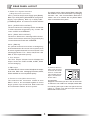
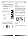
PUBLIC ADDRESS SYSTEM
OPERATION MANUAL
T-8000
VENUE MIXER
ZONE 1
ZONE 2
ZONE 3
ZONE 4
ZONE 5
ZONE 6
ZONE 7
ZONE 8
SOURCE UP SOURCE DOWN
SOURCE UP SOURCE DOWN
SOURCE UP SOURCE DOWN
SOURCE UP SOURCE DOWN
SOURCE UP SOURCE DOWN
SOURCE UP SOURCE DOWN
SOURCE UP SOURCE DOWN
SOURCE UP SOURCE DOWN
PAGE BUSY MIC1 PRIORITY
PAGE BUSY MIC1 PRIORITY
PAGE BUSY MIC1 PRIORITY
PAGE BUSY MIC1 PRIORITY
PAGE BUSY MIC1 PRIORITY
PAGE BUSY MIC1 PRIORITY
PAGE BUSY MIC1 PRIORITY
PAGE BUSY MIC1 PRIORITY
MIC1
4
5
MIC2
6
7
3
4
0
MIC3
6
7
0
5
6
8
2
0
4
8
0
8
2
9
1
10
5
9
1
0
10
8
8
9
1
10
8
2
9
1
10
5
7
8
0
8
2
9
1
0
10
9
1
0
10
FUNCTION
ENTER
BGM ALL
ESC
PAGE ALL
10
5
6
7
3
8
8
2
0
10
MASTER8
6
4
7
9
1
0
10
5
4
6
7
3
8
2
8
2
9
1
0
POWER
EMERGENCY
9
1
10
5
3
8
7
4
9
0
2
6
8
6
7
4
7
ZONE SELECT
OUTPUT LEVEL
MUSIC8
5
1
6
T-8000
VENUE MIXER
9
0
2
10
5
5
2
1
MASTER7
4
3
4
3
8
10
3
9
1
7
7
4
MASTER6
6
MIC8
6
9
0
2
10
5
5
1
6
3
8
4
3
4
3
2
10
MUSIC7
4
9
1
0
7
9
MUSIC6
7
MIC7
6
8
6
MASTER5
6
7
0
5
5
1
0
2
10
5
3
4
3
2
10
3
9
0
4
2
0
4
7
1
7
7
8
6
MASTER4
6
MIC6
6
9
0
2
10
5
3
8
2
5
3
8
0
4
7
5
1
10
MUSIC5
4
9
1
6
3
4
3
2
9
MUSIC4
MASTER3
4
7
7
8
6
7
MIC5
6
1
0
2
10
MASTER2
6
5
5
2
10
3
9
1
10
5
3
0
4
7
4
3
8
6
2
9
1
5
3
MASTER1
7
9
0
MUSIC3
4
7
3
MIC4
6
1
10
MUSIC2
4
5
2
9
1
10
MUSIC1
4
3
8
2
9
1
5
3
8
2
MONITOR
10
5
6
3
7
1
9
ON
8
2
0
OFF
10
Please follow the instructions in this manual to obtain the optimum results from this unit.
We also recommend that you keep this manual handy for future reference.
SAFETY PRECAUTIONS
Be sure to read the instructions in this section carefully before use.
Make sure to observe the instructions in this manual as the conventions of safety symbols and messages
regarded as very important precautions are included.
We also recommend you keep this instruction manual handy for future reference.
Safety Symbol and Message Conventions
Safety symbols and messages described below are used in this manual to prevent bodily injury and property
damage which could result from mishandling. Before operating your product, read this manual first and
understand the safety symbols and messages so you are thoroughly aware of the potential safety
Indicates a potentially hazardous situation which, if mishandled, could
result in death or serious personal injury.
Indicates a potentially hazardous situation which, if mishandled, could
result in moderate or minor personal injury, and/or property damage.
When Installing the Unit
Do not expose the unit to rain or an environment
where it may be splashed by water or other liquids,
as doing so may result in fire or electric shock.
Use the unit only with the voltage specified on the
unit. Using a voltage higher than that which is
specified may result in fire or electric shock.
Do not cut, kink, otherwise damage nor modify the
power supply cord. In addition, avoid using the
power cord in close proximity to heaters, and never
place heavy objects -- including the unit itself -- on
the power cord, as doing so may result in fire or
electric shock.
Be sure to replace the unit's terminal cover after
connection completion. Because high voltage is
applied to the speaker terminals, never touch these
terminals to avoid electric shock.
Be sure to ground to the safety ground (earth)
terminal to avoid electric shock. Never ground to a
gas pipe as a catastrophic disaster may result.
Avoid installing or mounting the unit in unstable
locations, such as on a rickety table or a slanted
surface. Doing so may result in the unit falling
down, causing personal injury and/or property
damage.
When the Unit is in Use
Should the following irregularity be found during
use, immediately switch off the power, disconnect
the power supply plug from the AC outlet and
contact your nearest ITC dealer. Make no further
attempt to operate the unit in this condition as this
may cause fire or electric shock.
If you detect smoke or a strange smell coming
from the unit.
If water or any metallic object gets into the unit
If the unit falls, or the unit case breaks
If the power supply cord is damaged (exposure of
the core, disconnection, etc.)
If it is malfunctioning (no tone sounds.)
To prevent a fire or electric shock, never open nor
remove the unit case as there are high voltage
components inside the unit. Refer all servicing to
your nearest ITC dealer.
Do not place cups, bowls, or other containers of
liquid or metallic objects on top of the unit. If they
accidentally spill into the unit, this may cause a fire
or electric shock.
Do not insert nor drop metallic objects or
flammable materials in the ventilation slots of the
unit's cover, as this may result in fire or electric
shock.
SAFETY PRECAUTIONS
When Installing the Unit
Never plug in nor remove the power supply plug
with wet hands, as doing so may cause electric
shock.
When unplugging the power supply cord, be sure
to grasp the power supply plug; never pull on the
cord itself. Operating the unit with a damaged
power supply cord may cause a fire or electric
shock.
When moving the unit, be sure to remove its power
supply cord from the wall outlet. Moving the unit
with the power cord connected to the outlet may
cause damage to the power cord, resulting in fire or
electric shock. When removing the power cord, be
sure to hold its plug to pull.
Do not block the ventilation slots in the unit's cover.
Doing so may cause heat to build up inside the unit
and result in fire.
Avoid installing the unit in humid or dusty locations,
in locations exposed to the direct sunlight, near the
heaters, or in locations generating sooty smoke or
steam as doing otherwise may result in fire or
electric shock.
When the Unit is in Use
Do not place heavy objects on the unit as this may
cause it to fall or break which may result in
personal injury and/or property damage. In
addition, the object itself may fall off and cause
injury and/or damage.
Make sure that the volume control is set to
minimum position before power is switched on.
Loud noise produced at high volume when power is
switched on can impair hearing.
Do not operate the unit for an extended period of
time with the sound distorting. This is an indication
of a malfunction, which in turn can cause heat to
generate and result in a fire.
Contact your ITC dealer as to the cleaning. If dust
is allowed to accumulate in the unit over a long
period of time, a fire or damage to the unit may
result.
If dust accumulates on the power supply plug or in
the wall AC outlet , a fire may result . Clean it
periodically. In addition,insert the plug in the wall
outlet securely.
Switch off the power,and unplug the power supply
plug from the AC outlet for safety purposes when
cleaning or leaving the unit unused for 10 days or
more. Doing otherwise may cause a fire or electric
shock.
An all-pole mains switch with a contact separation of at least 3 mm in each pole shall be incorporated in
the electrical installation of the building.
CONTENTS
1.INTRODUCTION ................................................................................................ 1
2.FRONT PANEL LAYOUT................................................................................... 1
3. REAR PANEL LAYOUT..................................................................................... 4
4.RS 485 COMMUNICATION PROTOCOL ........................................................ 9
5. SPECIFICATIONS ........................................................................................... 10
6.CONNECTION DIAGRAM................................................................................ 11
7.CONNECTION AND SETTING............................................................12
1. INTRODUCTION
The matrix & paging controller family comprise an 8 channel and 4 channel ones which are cater
for multi-zone ,paging andmulti-soucres selection system .They are complete solution for multi-zone,
multi-functional venues like entertainment places, large hotel,sport or grm centers,shopping mall and
airport ect.
T-8000 offer direct connection of up 8music source input ,8remote control panels.4 remote paging
consoles and one microphone input,all of these inputs can be freely allocated into different 8 zone outputs simultaneously.
2. FRONT PANEL LAYOUT
ZONE 1
ZONE 2
ZONE 3
ZONE 4
ZONE 5
ZONE 6
ZONE 7
ZONE 8
SOURCE UP SOURCE DOWN
SOURCE UP SOURCE DOWN
SOURCE UP SOURCE DOWN
SOURCE UP SOURCE DOWN
SOURCE UP SOURCE DOWN
SOURCE UP SOURCE DOWN
SOURCE UP SOURCE DOWN
SOURCE UP SOURCE DOWN
PAGE BUSY MIC1 PRIORITY
PAGE BUSY MIC1 PRIORITY
PAGE BUSY MIC1 PRIORITY
PAGE BUSY MIC1 PRIORITY
PAGE BUSY MIC1 PRIORITY
PAGE BUSY MIC1 PRIORITY
PAGE BUSY MIC1 PRIORITY
PAGE BUSY MIC1 PRIORITY
MIC1
5
4
MIC2
6
7
3
4
0
MIC3
6
7
10
0
5
6
7
3
0
0
6
4
7
0
4
6
4
7
3
9
1
0
10
4
7
8
2
9
1
0
10
6
4
7
0
4
9
1
10
4
8
2
9
1
10
5
7
4
8
2
0
9
0
10
BGM ALL
ESC
PAGE ALL
10
5
6
7
3
8
2
0
10
MASTER8
6
4
7
9
1
0
5
10
4
6
8
2
9
1
0
5
6
7
3
7
3
8
2
POWER
EMERGENCY
9
1
10
5
3
8
1
10
7
9
4
7
FUNCTION
ENTER
9
4
8
6
7
8
6
1
0
2
9
1
5
MASTER7
3
6
1
0
2
10
5
5
3
2
10
3
8
0
4
ZONE SELECT
OUTPUT LEVEL
MUSIC8
4
9
1
7
7
8
6
2
6
MIC8
6
9
0
MASTER6
3
5
1
10
3
8
6
7
0
7
10
5
4
3
2
MUSIC7
4
9
0
7
8
6
1
MIC7
6
9
0
MASTER5
3
8
2
5
5
1
MUSIC6
2
10
5
4
3
2
10
3
8
9
1
7
0
5
2
6
7
9
0
MASTER4
3
MIC6
6
8
10
3
8
6
3
8
2
7
10
5
5
1
MUSIC5
4
9
0
4
3
2
9
0
MASTER3
5
7
8
6
1
10
MASTER2
MIC5
6
1
MUSIC4
2
9
1
10
5
5
5
2
10
3
8
2
9
1
5
4
3
8
10
3
8
2
7
9
MUSIC3
4
MASTER1
MIC4
6
1
MUSIC2
4
5
2
9
1
MUSIC1
4
3
8
2
9
1
5
3
8
2
MONITOR
10
Select Source
Zone LED Display
Page Busy
MIC Priority Indicator
Monitor Zone Select
Monitor LED Display
MIC Priority Button
ESC
ENTER
BGM ALL
9
1
0
10
Monitor Zone Output Level
Monitor Volume
Music Volume
Master Volume
MIC Volume
Page All
1
ON
8
2
OFF
FRONT PANEL LAYOUT
1. Source Select
The source select button (1) is used to select the
source for the zone. Each zone has a separate
source selection button. There are 9 selectable
sources: Line sources 1 through 8 and a local
Microphone source.A different local source (remote
in wall mixer or source select/volume control)can
beconnected to each zone. A zone cannot select
the local source connected to another zone.Pressing
the source select button will cycle through all zones
5. MlCl Priority Button
The MIC1 Priority button (5) will enable/disable
the MIC1priority paging function.When enabled,
MIC1will override zones 1-8and all local inputs,
if a signal is present on the MIC1 input.When dis
-abled,MIC1 will mix with lines 1-8 and local inputs
if required.This Microphone input has been designed
to give global priority over all other inputs if enabled
via the front panel. The MIC1 priority setting is not
saved when the T-8000 is switched off, and will
return to its default state on powered back on.
The default state of the MIC1 Priority is disabled.
in sequence:1, 2, 3, 4, 5, 6,7, 8, L,and OF.To select
a required source, press the source select button
(1). Once the display shows the desired source, press
6. Music Volume
The Music Volume control knob (6) controls the
selected source (zones 1-8 and local input) input
level. If the system is used with Remote Control
Panels, the Music Volume knob will be disabled
for zones where a remote control panel is connected.
Source Music Volume level will be controlled
at the remote control panel only.
the ENTER (14) buttonto confirm and the change to
the selected source.
Note:
The source will only change after the ENTER (14)
button is pressed. If the ENTER(14) button is not
pressed,the source selection will return to previous
setting after 10 seconds.When the system is used
in conjunction with remote control panels,the zone
source select button will be disabled when a remote
controlpanel is connected to a zone .In this instance,
the source selection can only be controlled via the
remote control panel in the event power is lost,the last
source selection settings are automatically saved
and the unit will return to its previously configured
source selections when powered back on.
7. Master Volume
The Master Volume control knob (7) will control
the combined MIC1 and Source Output Volume
Level, if the MIC1 input has been enabled for a
zone. The Master Volume control knob will not
control the Paging Console Public Address Volume
Level,or the Line 8 Source Input Volume Level when
the Line 8 Source Input Priority Function is enabled.
This function has been designedasa global BGM
input if required.
2. Zone LED Display
The Single Digit Zone LED Display will display the
selected source number: lines 1-8 and local input
shown as L.
8. MIC1 Volume
The MIC1 Volume control knob (8) will control the
MIC1 input level if this global mic has been configured
to operate within the zone.ITC Commercial Series
T-8000 User Manual.
3. Page Busy
The Zone Page Busy indicator LED (3) will illuminate
amber to indicate a paging microphone is paging to
this zone.
4. MIC1 Priority Indicator
The MIC1 Priority Indicator LED (4) will illuminate
blue indicating the Zone MIC1 priority paging func
-tion is enabled.
2
FRONT PANEL LAYOUT
9. Monitor ZONE SELECT
The ZONE SELECT button (9) is used to select
one of the 8 zones to be monitored.Pressing the
zone select button will cycle through allzones in
sequence as follows:1,2,3,4, 5,6, 7, 8, and OFF.
A zone can be selected pressing the ZONE SELECT
button.Once the display shows the desired zone,
press the ENTER button to confirm and change
to the selected zone.
12. Monitor Volume
The Monitor Volume control knob (12) will control
the in-built Monitor Speaker volume level.
13. ESC
The ESC button (13) is used to cancel the selection
of source select,monitor zone select and BGM
function buttons.
14. ENTER
The ENTER button (14) is used to confirm selection
of source select,monitor zone select and BGM
function buttons.
Note:
The zone will only change after the ENTER button
is pressed, otherwise the source selection will be
returned to its previous setting after 10 seconds.
The monitor zone function enables the audio output
from a zone to be monitored through a small speaker
on the front panel.This is particularly useful when
controlling the audio in a remote zone or testing
the system.
15. BGM ALL
The BGM ALL button (15) is used to select the
same source for all 8 zones simultaneously.To
confirm the BGM ALL selection,press ENTER.
Note:
The BGM ALL selection will only be confirmed
after the ENTER button is pressed ,otherwise
the source selection will be return to previous
setting after 10 seconds.In the event power is
lost, the BGM ALL selection settings will be
saved and the unit will return to the previous
BGM ALL setting when powe red back on.
10. Monitor Zone LED Display
The Single Digit Monitor Zone LED Display (10)
will display the selected zone numbers,1-8.
11. Monitor Zone Output Level
The 5 LED Monitor Zone Output Level Meter(11)
will provide visual indication of the audio signal
level for a selected zone.
3
3. REAR PANEL LAYOUT
EXTENSION LINK
OUTPUT
+
3
-
2
0V
1
0.775V/600
+
3
-
2
0V
1
OUTPUT
0.775V/600
+
LINK IN
dB
HF
+10
dB
-10
LF
+10
dB
-10
LINK OUT
dB
HF
+10
dB
-10
LF
+10
dB
-10
3
-
2
1
OUTPUT
0.775V/600
LF
+10
dB
-10
dB
HF
+10
dB
-10
LF
+10
dB
-10
PAGE
REMOTE
WALL CONTROL
dB
HF
+10
dB
-10
2
1
LF
+10
dB
-10
+
3
-
2
0V
1
OUTPUT
0.775V/600
LF
+10
dB
-10
PAGE
3
-
2
1
0.775V/600
+
GAIN
dB
HF
+10
dB
-10
LF
+10
dB
-10
GAIN
dB
HF
+10
dB
-10
LF
+10
dB
-10
-
-
ZONE
6
+
dB
-
ZONE
7
+
dB
-
PAGE
REMOTE
WALL CONTROL
DISABLE
ENABLE
DISABLE
ENABLE
ZONE
8
+
dB
-
PAGE
REMOTE
WALL CONTROL
REMOTE
WALL CONTROL
DISABLE
ENABLE
OUTPUT
+
0V
+
dB
+10
dB
-10
-
REMOTE
WALL CONTROL
DISABLE
ENABLE
0.775V/600
HF
ZONE
5
+
dB
-
PAGE
OUTPUT
GAIN
-
ZONE
4
+
dB
-
REMOTE
WALL CONTROL
DISABLE
ENABLE
3
-
+
GAIN
-
+
dB
-
+
0V
+
GAIN
ZONE
3
EMC IN
GROUND
EVAC
ALERT
+ GAIN
GAIN
- dB +
- dB +
- dB +
- dB +
L
L
195mV-2V/47K
L
G
+
3
-
dB
1
2
0V
LINE 6
+ -
MIC:5mV LINE:350mV
G
+
3
-
dB
1
2
0V
300mV-1.1V/10K
MIC:5mV LINE:350mV
G
+
REMOTE SOURCE 6
GAIN
3
-
dB
1
2
0V
300mV-1.1V/10K
LINE 7
+ -
REMOTE SOURCE 5
GAIN
REMOTE
WALL CONTROL
DISABLE
ENABLE
+
DISABLE
ENABLE
REMOTE SOURCE 7
GAIN
3
-
dB
1
2
0V
300mV-1.1V/10K
dB
1
300mV-1.1V/10K
+
0V
REMOTE SOURCE 8
GAIN
3
2
dB
1
300mV-1.1V/10K
LINE 8
MIC:5mV LINE:350mV
+ -
G
LINE
MIC
PHANTOM
R
GAIN
195mV-2V/47K
2
300mV-1.1V/10K
LINE 5
GAIN
L
3
0V
REMOTE SOURCE 4
GAIN
LINE
MIC
PHANTOM
R
+
-
dB
1
300mV-1.1V/10K
LINE
MIC
PHANTOM
2
0V
LINE 4
LINE 3
R
3
-
dB
1
LINE
MIC
PHANTOM
2
300mV-1.1V/10K
LINE 2
R
+
-
COMMON
3
+
+
-
dB
+
LINE 1
-
+
REMOTE SOURCE 3
GAIN
-
dB
REMOTE SOURCE 2
GAIN
+
+
0V
-
REMOTE SOURCE 1
GAIN
-
EMC
INPUT
+
TONE
OUTPUT
-
BATT SUPPLY
2A
24V
+
0V
+
SLAVE3
+10
dB
-10
-
DISABLE
ENABLE
0.775V/600
-
SLAVE2
dB
HF
PAGE
OUTPUT
+
SLAVE1
1
-
MASTER
2
+
1
3
-
+
GAIN
ZONE
2
+
dB
-
PAGE
+
0V
-
4
0.775V/600
775mV/10K
1 2
ON
OUTPUT
+
3
FIRE ALARM
CONTACT CLOSURE
2 3 4 5 6 7 8 G
1
-
REMOTE
WALL CONTROL
230V
115V
INPUT VOLTAGE SELECTOR
2
+
GAIN
ZONE
1
+
dB
-
PAGE
3
-
+
GAIN
-
~115V/230V 50-60Hz
+
0V
MICROPHONE 1
PAGING MIC1
PAGING MIC2
GAIN
GAIN
- dB +
- dB +
MIC:5mV LINE:350mV
GAIN
LF
HF
dB
-8 dB +8
-8 dB +8
5mV-300mV/680
1
Dip Switches
9
LF Bass
2
EVAC / Fire System Interface
10
Output
17 Line Inputs
18 Paging Console Inputs
3
Tone Output
11
Gain
19 Paging MIC Gain
4
EMC Input
12
HF
20 MIC 1 Input
5
Extension Link
13
Enable/Disable Switch
21 MIC 1 Gain
6
Remote Source
14
Remote Source Gain
22 MIC 1 Bass
7
Remote Control Input
15
Fire Alarm
23 MIC 1 H
8
Page
16 Line Gain
1. Dip Switches
4
MASTER
SLAVE1
SLAVE2
SLAVE3
1 2
ON
3
4
3
4
Master
Slave 1
MASTER
SLAVE1
SLAVE2
SLAVE3
For the avoidance of doubt, if a Matrix unit is confi
-gured as a slave,the slave Matrix Inputs 1 - 8,MIC1
and remote paging consoles inputs will be disabled.
However, the optional wall plates can be used to operate
these additional zones.
1 2
ON
MASTER
SLAVE1
SLAVE2
SLAVE3
If you are expanding the system, only line in puts
1-8 ,MIC 1 and 2 x Remote Paging Consoles of
the Master Matrix are enabled .All Slave Matrix
units connected to the Master will use the Master
Matrix inputs.
MASTER
SLAVE1
SLAVE2
SLAVE3
Dip switch settings are as follows for configuring
the T-8000 as a Master or Slave:
Dip switches set the Matrix system address.If the
system is to be expanded, each ITC unit must be
defined as Master, Slave1,2or3.
1 2
ON
1 2
ON
3
4
Slave 2
3
4
Slave 3
REAR PANEL LAYOUT
2. EVAC / Fire System Interface
(7 Way Pheonix Connector)
PIN 1- [+24V DC 24V] Power supply input.(Battery
Back Up or UPS)PIN 2- [GROUND DC 24V] Power
Supply input .(Battery Back Up or UPS) PIN3 [COMMON],Which is Common for ALERT & EVAC
The Matrix can be linked with a DB37 Cable.This
will enable the Line I-8 Sources,MIC1 input,Paging
Consoles I & 2 , and Communication Data of the
master unit to be shared with any Slave Matrix
Units connected to the system.
PIN 4 - [ALERT DRY CONTACT]
The built-inalertvoice message will be broadcast
to all 8 zones after triggered by dry contact bet
-ween ALERT and COMMON.
PIN 5 - [EVAC DRY CONTACT]
The built-in EVACvoice message will be broad
-casted to all 8 zones after being triggered by dry
contact between EVAC and COMMON.
PIN 6 - [EMC IN]
An optional external voice alarm message may
be broadcasted to all 8 zones of the system,when
an alarm signalis detected from an external voice
messagegenerator. Fire alarm, alert,EVAC and
EMC in are of equivalent priority
3. Tone Output
The Tone Output Volume Control will adjust the
output level of the FIRE ALARM, ALERT, EVAC
voice messaging.
4. EMC Input
The EMC INPUT Volume control will adjust the output
level of the EMC voice messaging.Fire alarm,ALERT,
EVAC and EMC in are of equivalent priority.
6. Remote Source
Each zone can have
a remote line level
source connected.
The remote source
input connector is
shown here.
5. Extension Link (DB37 Connector)
The extension link connectors enable 8 zone
Matrix units to be connected together to form a
larger system. Up to four 8 Zone Matrix units can
be connected to make a 32 zone system.
This has been
designed to be used if you don't wish to use a local
in wall mixer. This could be for example,a Radio MIC.
On selecting this input via the front panel controls,
select "L". Please note that this input cannot be
distributed to other zones.
5
REAR PANEL LAYOUT
T-8000D assignment order
is as below:
Local zone source level has three adjustments,
namely:
1 NC
2 NC
3 MUTE
4 GND
5 DC+24V
6 DC+24V
7 AUDIO IN +
8 AUDIO IN -
a. Gain control for the local source Input on the
rear of the Matrix
b. A Music level control on the Matrix front panel
or the remote wall control
c. A Master level control on the Matrix front panel.
Please Note:
The input signal is set at 300mV-1 .lv/1 OK Ohm
1
2. The remote wall panel will be selectable on
the system.Therefore,selectable sources will
be L (local) as well as source line1 to 8.
T-8000B assignment order
is as below:
1 RS485B
2 RS485A
3 NC
4 GND
5 DC+24V
6 DC+24V
7 AUDIO IN +
8 AUDIO IN 2
3
A
NC
4
5
6
GND +24V +24V
2
3
B
A
NC
4
5
6
GND +24V +24V
5
10. Output
Every Zone has an
AUDIO OUTPUT
6
7
8
AUDIO IN + AUDIO IN +
R
connector; this should
7
be connected to the
Audio Amplifier for
the designated Audio
Zone.
Zone Audio Output Connections are as labeled.
8
AUDIO IN + AUDIO IN +
T-8000C assignment order
is as below:
1 RS485B
2 RS485A
3 NC
4 GND
5 DC+24V
6 DC+24V
7 NC
8 NC
1
4
9. LF Bass
The Zone LF Bass
of the Zone Output
can be controlled
by adjusting the LF
Bass Level Control.
This Level Control
will provide adjustment of the 100Hz Audio
Frequency by± 10dB.
Every Zone has a LF Bass Level Control which
enables the LF Bass Level of each zone to be
set independently of other zones.
Local Source Connections are as follows:
1. A remote wall panel can be connected to the
Matrix, with only one remote wall controller
able to be connected per zone.
B
3
MUTE GND +24V +24V
8. Page
The Zone Page Output Volume Control will adjust
the output paging level for the Zone.Every Zone has
a Page Output Volume Control which enables the
paging level of each zone to be set independently of
other zones.
7. Remote Control Panel Input
Each of the eight zones can have a remote control
panel connected . The Remote control Panel will
enable the source and volume to be controlled from
a remote location. Each zonehas its own RJ45 input
connector allowing for a Remote Control Panel to be
connected for control over each zone.
1
2
NC
7
11. Gain
The Zone Gain control
will set the maximum
Source Output Volume
Level for the Zone.This
will ensure the user
cannot adjust the Audio Level too highusing
the Master,MIC1and Music Level ControlKnobs
on the Front Panel. Gain will set the Maximum
Output Volume of Line Source and MICI.It will
have no control over the Paging Level.
8
NC
6
REAR PANEL LAYOUT
12. HF
The Zone HF Treble of the
Zone Output can be controlled
by adjusting the HF Treble Level
The EMC Input will only take priorityand broad
-cast to zones where there is a Zone FireAlarm
Dry Contact Closure.Each zone has aseparate
Fire Alarm Dry Contact.Fire alarm, alert,EVAC
and EMC in are of equivalent priority.
dB
Control. This Level Control will
provide adjustment of the 100Hz
AudioFrequency by 10dB.
Every Zone has a HF Treble Level Control
which enables the HF Treble Level of each
zone to be set independently of other zones.
13. Enable/Disable Switch
16. Line Gain
The System Line Source Input Signal Levels
can be adjusted from 190mV to 200mV using
the Line Source Input Gain control. This will
enable the signal level of all sources to be
equalized there by ensuring Output Volume
Level remains constant when switching from
one source to another source.
If a Zone Remote Wall Control
Panel is to be used with the
System, The R J45 Remote
Control Panel Input needs to
be enabled. The RJ45 Remote
Control Panel Input is enabled/
disabled by pressing the Enable / Disable
Switch. Every Zone has an RJ45 Remote
Control Panel Input Enable / Disable Switch.
NOTE: Only Enable when a Zone Remote
Wall Control Panel is connected.
All system source inputs L(lines 1-8) have a
separate Gain Control.
14. Remote Source Gain
The Zone Local Source Input
Signal Level can be adjusted
from 190mV to 200mV using
the Remote Source Gain con
17. Line Inputs
The system has 4 Line Inputs,as well as 4 inputs
selectable as mic or line with phantom power
available.
Every Line Source Input has a dual RCA Phono
Connect or, which will enable a Stereo Source
Signal to be connected. Note, however, this is a
Mono system and a StereoInput will be combined
to give a Mono Output.
-trol. This will enable the signal
level of all sources to be equali
-zed therebyensuring Output
Volume Level remains constant when
switching from one source to another
source. Every Zone Remote Source
Input has a Gain Control.
15. Fire Alarm
There are Fire Alarm dry contacts for zones
1-8. When Dry Contact is detected the EMC
Input will be open and take priority over all
other inputs.
7
REAR PANEL LAYOUT
20. MIC1 Input
The balanced MIC1 input XLR type has an
impedance of 600ohms. Each zone has aMIC1
Priority Button.
The Line Inputs have an impedance of 47 kohms.
1. Line 1-8 source inputs will be selectable using the
Source Select control on the front of the Matrix. 2)
2. The selected source input number will be indicated
on the Matrix zone display.
3. Any extension Matrix unit connected to the system
will use sources line 1-8 from the master Matrix.
4. Only one set of input sources for lines1-8 can will
be connected per system.
Each zone has a MIC1 priority button. When the
MIC1 priority button is not enabled,MIC1 will be
mixed with the line inputs on each zone (1-8 or L).
When the MIC1 priority button is enabled,MIC1
will take priority over all line inputs (1 - 8 or L)
as well the wall control panel for that zone.
18. Paging Console Inputs
Up to two paging consoles can be
connected to the system simul
-taneously via the two paging con
-sole Rj45 input ports.The paging
consoles will have equal priority
and will operate on a first come
MIC1 will have priority only on Zones where the
MIC1 Priority Switch is enabled on the front panel.
Zones where the MIC1 priority switch is not enabled,
MIC1 will mix with the Source Selected for the Zone.
The MIC1 level will be controlled by the MIC1 Level
Adjustment Knob and the Master Level Adjustment
Knob.
first served basis . The RJ45 pin
assignment order is as below:
The MIC1 signal will be sent to any extension
Matrix connected to the system.
1. RS485 B
2. RS485 A
3. GND
4. + 24V (OUT)
5. GND
6. + 24V (OUT)
7. AUDIO IN+
8, AUDIO IN 19. Paging MIC Gain
The Paging MIC Gain control will adjust the Paging
MIC Input Signal Level. Each Paging MIC will have
its own gain control.There by each Paging MIC can
be set independently of the other Paging MICs.
21. MlCl Gain
The MIC1 Gain controls the MIC1 range from
5mV to 300mV.
22. MlCl Bass
The MIC1 Bass controls the MIC1 gain at 100hz
( 10dB).
8
4. RS 485 COMMUNICATION PROTOCOL
Status Data To Paging Console
RS 485 Communication Protocol
After getting paging data from the remote paging
console, the Matrix sends zone status data to the
paging console in the following format:
Baud Rate: 57600bps/S Parity
Check: Odd parity check
Data: 16 bytes
Accumulation = 2nd data byte
+3rd data byte + 4th data byte
hA 1 E Matrix address code zone data AM
AA: data head
1 E: Zone status feedback to paging console
Matrix address code=
01 : master
02: slave 1
03: slave 2
04: slave 3
3 zone data: the zone data is in 8 bytes,
0: no paging
1 :paging, ie: binary system
00000011 B:zonel and zone 2 busy
0000100B: zone 3 busy,
11111111 B: all 8 zone busy
AM: (accumulation = 2nd data byte
+ 3rd data byte + 4th data byte)
T-8000 Inquiry Data
TheT-8000 sends inquiry data to2 remote paging
consoles ,8 remote wall panels and extension
Matrix. The new data will feedback to the Matrix
when any new data has been checked.Any exten
-sion T-8000 will only enquire to its own 8 remote
wall panels only.
Inquiry Data To Paging Console
The T-8000 sends the inquiry data to remote
paging consoles in the following format:
AA 10 00 00 AM (accumulation)
AA: data head
10: inquiry to the paging console
00: meaningless
AM: (accumulation = 2nd data byte
+ 3rd data byte + 4th data byte)
Inquiry Data To Remote Wall Plate
If the zone is not controlled by a remote wall
plate , the inquiry data will not be sent to this
zone.
Feedback Data From PagingConsole
The inquiry command which is from the Matrix to
the remote wall plate is both inquiry and status
data to update the wall plate status, ie:source
input, zone volume.The inquiry data format is:
hA 20 line input volume AM
hA: data head
20: inquiry to wall plate
line input: source input
01 : line 1
02 : line 2
The feedback data from the remote paging console
to the Matrix after got inquiry andready for paging
format as:
AA 11 Matrix address code zone data AM
AA: data head
11 : zone paging command
Matrix address code:
01 : master matrix,
02 : extension matrix 1
03 : extension matrix 2
04 : extension matrix 3
3 zone data: the zone data is in 8 bytes
0 : no paging
1 : paging, ie: binary system
00000011 B : zone1 and zone 2 paging
00000100B : zone 3 paging
11111111 B : all 8 zone paging
AM: (accumulation = 2nd data byte
+ 3rd data byte + 4th data byte)
08 : line 8
09 : remote sources input
volume: volume level
00 : 0 level
01:1 level
AM: (accumulation = 2nd data byte
+ 3rd data byte + 4th data byte)
9
RS 485 COMMUNICATION PROTOCOL
Feedback Data From The Wall Plate
Inquiry Data To Extension Matrix
The feedback data from the wall plate to the Matrix
delivered in the following format:
AA 21 line input volume AM
AA: data head
21 : feedback data from wall plate
to Matrix line input: source input
01 : line 1
02 : line 2
The Matrix inquiry data to the extension Matrix
format as:
AA 30 00 00 AM
08 : line 8
09 : remote sources input
volume: volume level
00 : 0 level
01:1 level
AM: (accumulation= 2nd data byte
+ 3rd data byte + 4th data byte)
5. SPECIFICATIONS
Model
T-8000
LINE 1-4 input
195mV-2v/10k
MIC:5mV/600 ,Line:350mV/10k ,phantom power:+48V
Line 5-7 input
Microphone
Remote Paging Station
Remote Control Panel
Tone Control
Outputs
Frequency Response
EMC input
Microphone S/N Ratio
Line S/N Ratio
Crosstalk
THD
Indicator
Priority
5mV-280mV/600
300mV-1.1V/10k
300mV-1.1V/10k
100Hz 10dB,10KHz 10dB
0.775V/600
MIC:80Hz~18KHz(+1/-3dB),line:20Hz~20KHz(+1/-3dB)
775mV/10K
65dB
85dB
65dB
0.07%
Power,Mic1,paging busy & monitor output
Mic1,voice alarm, local mic paging,
remote zone paging, line 1-8
Communication Speed
Communication port
4800bps
Communication Protocol
RS485
Power Consumption
20W
Power Supply
~110V/60Hz and~240V/50Hz& DC 24V
Dimensions
484x304x132mm
Weight
6kg
RJ45
10
6. CONNECTION DIAGRAM
Remote control pancls
PUSH
LINE INPUT
SOURCE SOURCE
UP
DOWN
MIC1
MIC1
ON
2
5
4
ON
ON
MIC2
6
MUSIC
MUTE
8
2
6
7
3
8
2
9
1
0
5
4
7
3
1
3
9
1
10
0
10
SOURCE SOURCE
UP
DOWN
1
1
2
2
MUSIC
LEVEL
SOURCE
LEVEL
3
4
5
4
6
7
3
5
0
7
8
2
9
1
7
MIC
0
MIC
PUSH
3
7
3
2
0
MIC1
5
4
5
1
8
6
2
6
10
HF
LF
HF
LF
9
1
0
8
MIC2
3
8
2
7
8
1
7
3
3
9
1
10
MIC2
4
6
2
9
1
10
5
4
6
3
8
2
6
5
4
PUSH
10
-
-
+
-
+
-
+
+
SOURCE LEVEL
MIC 1 input
Line 1-8 inputs
1-8 zone speaker outputs
ZONE 1
ZONE 2
ZONE 3
ZONE 4
ZONE 5
ZONE 6
ZONE 7
ZONE 8
SOURCE UP SOURCE DOWN
SOURCE UP SOURCE DOWN
SOURCE UP SOURCE DOWN
SOURCE UP SOURCE DOWN
SOURCE UP SOURCE DOWN
SOURCE UP SOURCE DOWN
SOURCE UP SOURCE DOWN
SOURCE UP SOURCE DOWN
PAGE BUSY MIC1 PRIORITY
MIC1
5
4
PAGE BUSY MIC1 PRIORITY
MIC2
6
0
PAGE BUSY MIC1 PRIORITY
MIC3
6
7
3
8
0
5
4
6
0
0
9
1
0
9
1
10
0
0
9
1
10
0
9
1
10
0
0
7
8
0
10
0
0
ON
8
OFF
9
1
9
1
7
2
8
10
6
3
7
2
9
1
5
4
6
3
8
10
5
4
7
POWER
EMERGENCY
9
1
MASTER8
6
2
9
1
10
BGM ALL
PAGE ALL
ESC
6
2
10
5
3
8
5
3
8
0
4
7
ENTER
10
4
7
9
1
MASTER7
6
2
FUNCTION
8
0
2
10
5
3
8
7
9
1
6
3
8
0
4
7
5
4
7
9
1
MASTER6
6
ZONE SELECT
6
2
10
MUSIC8
6
2
10
5
2
5
4
3
8
0
3
8
0
4
3
8
5
4
7
9
1
7
7
9
1
T-8000
VENUE MIXER
OUTPUT LEVEL
PAGE BUSY MIC1 PRIORITY
MIC8
6
2
10
MUSIC7
6
2
MASTER5
6
2
9
1
10
0
5
4
3
8
9
1
MUSIC6
5
4
3
8
10
5
3
8
7
2
10
MUSIC5
7
9
0
4
7
2
PAGE BUSY MIC1 PRIORITY
MIC7
6
3
8
6
1
6
3
8
5
4
3
MASTER4
5
4
7
5
4
7
9
1
0
2
10
MASTER3
6
2
PAGE BUSY MIC1 PRIORITY
MIC6
6
2
10
MUSIC4
8
9
1
10
5
4
3
8
7
2
9
1
MASTER2
6
7
0
5
4
3
8
9
1
6
3
8
2
10
5
4
5
4
7
3
8
0
5
4
7
9
1
3
2
7
2
10
MUSIC3
6
3
2
MASTER1
PAGE BUSY MIC1 PRIORITY
MIC5
6
3
8
0
5
4
7
9
1
10
MUSIC2
MUSIC1
PAGE BUSY MIC1 PRIORITY
MIC4
6
2
9
1
10
5
4
3
8
2
9
1
5
4
7
3
2
MONITOR
0
10
10
Master matrix
8 remote control panel
PUSH
LINE INPUT
SOURCE SOURCE
UP
DOWN
MIC1
MIC1
ON
2
5
4
ON
ON
MUSIC
MUTE
2
MUSIC
LEVEL
SOURCE
LEVEL
3
4
5
4
6
9
1
0
7
7
8
2
0
MIC
8
PUSH
2
8
0
6
3
6
10
7
8
9
0
10
MIC2
HF
LF
HF
LF
3
9
1
0
8
1
8
2
7
8
PAGING MIC 1
2
7
3
9
1
10
MIC1
5
4
5
1
6
1
10
MIC2
4
7
5
3
2
9
1
SOURCE SOURCE
UP
DOWN
3
6
3
2
9
1
10
5
4
6
3
8
2
6
5
4
7
3
5
PUSH
MIC
MIC2
4
7
2
0
1
2
6
3
1
3
1
10
-
-
+
-
+
-
+
+
SOURCE LEVEL
LINK
9-16 zone speaker outputs
ZONE 1
ZONE 2
ZONE 3
ZONE 4
ZONE 5
ZONE 6
ZONE 7
ZONE 8
SOURCE UP SOURCE DOWN
SOURCE UP SOURCE DOWN
SOURCE UP SOURCE DOWN
SOURCE UP SOURCE DOWN
SOURCE UP SOURCE DOWN
SOURCE UP SOURCE DOWN
SOURCE UP SOURCE DOWN
SOURCE UP SOURCE DOWN
PAGE BUSY MIC1 PRIORITY
MIC1
5
4
PAGE BUSY MIC1 PRIORITY
MIC2
6
0
PAGE BUSY MIC1 PRIORITY
MIC3
6
7
3
8
0
5
4
6
6
0
0
4
6
4
7
3
0
4
7
0
0
4
7
0
6
0
6
0
7
8
0
6
10
0
ON
7
8
2
8
OFF
9
1
9
1
6
3
7
2
10
5
4
6
3
8
9
1
0
5
4
7
2
10
POWER
EMERGENCY
9
1
MASTER8
3
8
9
1
10
PAGE ALL
ESC
6
2
10
5
4
7
2
9
1
5
3
8
0
3
8
2
10
BGM ALL
ENTER
10
4
7
9
1
MASTER7
4
7
3
8
9
1
FUNCTION
8
0
2
10
5
7
9
1
6
3
8
0
5
4
7
9
1
MASTER6
ZONE SELECT
6
2
10
MUSIC8
6
2
10
5
5
4
3
8
0
3
8
6
2
10
5
4
7
9
0
7
9
1
T-8000
VENUE MIXER
OUTPUT LEVEL
PAGE BUSY MIC1 PRIORITY
MIC8
6
2
10
MUSIC7
6
1
MASTER5
3
8
9
1
10
5
2
10
5
4
7
2
9
1
10
0
6
3
8
2
9
1
6
3
8
2
0
5
4
3
8
9
1
MUSIC6
3
8
9
1
MASTER4
5
7
2
10
4
7
2
10
MASTER3
PAGE BUSY MIC1 PRIORITY
MIC7
6
3
8
0
5
4
7
9
1
6
3
8
9
1
10
5
5
4
7
2
9
1
MASTER2
PAGE BUSY MIC1 PRIORITY
MIC6
6
2
10
MUSIC5
6
3
8
2
10
5
0
5
4
3
8
9
1
MUSIC4
5
4
7
3
8
9
1
0
5
4
7
3
2
MASTER1
7
2
10
MUSIC3
PAGE BUSY MIC1 PRIORITY
MIC5
6
3
8
0
5
4
7
9
1
10
MUSIC2
PAGE BUSY MIC1 PRIORITY
MIC4
6
2
9
1
10
5
4
3
8
2
9
1
5
4
7
3
2
MUSIC1
MONITOR
0
10
10
Extension matrix 1
8 remote control panel
PAGING MIC 2
PUSH
LINE INPUT
SOURCE SOURCE
UP
DOWN
MIC1
MIC1
ON
2
5
4
ON
ON
MIC2
6
MUSIC
MUTE
8
2
6
7
3
8
2
9
1
0
5
4
7
3
1
3
9
1
10
0
10
SOURCE SOURCE
UP
DOWN
1
1
2
2
MUSIC
LEVEL
SOURCE
LEVEL
3
4
5
4
6
7
3
5
0
7
8
2
9
1
7
MIC
0
MIC
PUSH
3
7
3
2
0
MIC1
5
4
5
1
8
6
2
6
10
HF
LF
HF
LF
9
1
0
8
MIC2
3
8
2
7
8
1
7
3
3
9
1
10
MIC2
4
6
2
9
1
10
5
4
6
3
8
2
6
5
4
PUSH
10
-
-
+
-
+
-
+
+
SOURCE LEVEL
LINK
17-24 zone speaker outputs
ZONE 1
ZONE 2
ZONE 3
ZONE 4
ZONE 5
ZONE 6
ZONE 7
ZONE 8
SOURCE UP SOURCE DOWN
SOURCE UP SOURCE DOWN
SOURCE UP SOURCE DOWN
SOURCE UP SOURCE DOWN
SOURCE UP SOURCE DOWN
SOURCE UP SOURCE DOWN
SOURCE UP SOURCE DOWN
SOURCE UP SOURCE DOWN
PAGE BUSY MIC1 PRIORITY
MIC1
5
4
PAGE BUSY MIC1 PRIORITY
MIC2
6
0
PAGE BUSY MIC1 PRIORITY
MIC3
6
0
7
3
7
0
6
0
8
2
9
1
0
0
8
0
8
2
0
8
0
8
0
7
8
0
10
8
0
0
ON
8
0
10
OFF
9
1
9
1
7
2
8
2
6
3
7
10
5
4
6
3
9
1
5
4
2
POWER
EMERGENCY
9
1
MASTER8
6
7
10
PAGE ALL
ESC
6
2
10
5
3
9
1
10
BGM ALL
ENTER
10
5
3
8
0
4
2
9
1
10
7
9
1
MASTER7
6
7
FUNCTION
8
0
4
2
10
5
3
7
9
1
MUSIC8
6
3
8
0
4
7
2
9
1
7
9
1
MASTER6
6
ZONE SELECT
6
2
10
5
4
2
10
5
3
5
4
3
8
0
6
3
8
0
4
7
10
7
9
1
MASTER5
6
7
9
1
MUSIC7
T-8000
VENUE MIXER
OUTPUT LEVEL
PAGE BUSY MIC1 PRIORITY
MIC8
6
2
10
5
4
2
10
5
4
3
9
1
10
0
5
4
3
8
9
1
MUSIC6
6
3
8
9
1
7
2
9
1
10
7
2
MASTER4
6
3
PAGE BUSY MIC1 PRIORITY
MIC7
7
2
10
5
4
6
3
8
0
6
5
4
7
9
1
MUSIC5
10
5
4
7
PAGE BUSY MIC1 PRIORITY
MIC6
6
2
10
5
3
8
0
6
3
8
2
7
9
1
MASTER3
5
4
7
5
4
3
8
0
4
2
10
MASTER2
5
4
3
7
9
1
MUSIC4
6
3
8
9
1
10
MASTER1
PAGE BUSY MIC1 PRIORITY
MIC5
6
2
10
5
4
2
9
0
6
3
8
2
1
5
4
5
3
8
0
MUSIC3
6
4
7
9
1
10
MUSIC2
PAGE BUSY MIC1 PRIORITY
MIC4
6
2
9
1
5
3
8
2
10
5
4
4
7
3
8
9
1
5
4
7
3
2
MUSIC1
MONITOR
10
Extension matrix 2
8 remote control panel
PUSH
LINE INPUT
SOURCE SOURCE
UP
DOWN
MIC1
MIC1
ON
2
5
4
ON
ON
MIC2
6
MUSIC
MUTE
8
2
9
1
0
10
5
4
7
3
1
3
6
7
3
8
2
9
1
0
10
SOURCE SOURCE
UP
DOWN
1
1
2
2
MUSIC
LEVEL
SOURCE
LEVEL
3
4
5
4
6
4
7
3
5
0
7
8
2
9
1
7
9
1
10
0
5
4
6
3
8
2
6
5
PUSH
MIC
MIC
7
2
4
5
1
8
2
0
5
MIC1
6
6
10
MIC2
HF
LF
HF
LF
9
1
0
8
1
3
8
2
7
8
2
7
3
3
9
1
10
MIC2
4
6
3
PUSH
3
10
-
-
+
-
+
+
-
+
SOURCE LEVEL
LINK
25-32 zone speaker outputs
ZONE 1
ZONE 2
ZONE 3
ZONE 4
ZONE 5
ZONE 6
ZONE 7
ZONE 8
SOURCE UP SOURCE DOWN
SOURCE UP SOURCE DOWN
SOURCE UP SOURCE DOWN
SOURCE UP SOURCE DOWN
SOURCE UP SOURCE DOWN
SOURCE UP SOURCE DOWN
SOURCE UP SOURCE DOWN
SOURCE UP SOURCE DOWN
PAGE BUSY MIC1 PRIORITY
MIC1
4
5
PAGE BUSY MIC1 PRIORITY
MIC2
6
7
3
4
0
7
5
0
6
7
3
0
7
0
6
7
3
9
1
0
10
7
3
8
2
7
9
1
0
10
9
1
10
7
10
7
9
1
0
10
7
0
10
BGM ALL
PAGE ALL
7
8
0
4
7
10
9
1
0
5
10
4
6
8
2
9
1
0
10
5
6
7
3
7
3
8
2
POWER
EMERGENCY
9
1
MASTER8
6
Extension matrix 3
11
FUNCTION
ENTER
ESC
6
2
10
5
3
8
9
1
8
10
5
3
8
0
4
2
7
9
0
4
9
1
7
3
8
2
ZONE SELECT
OUTPUT LEVEL
6
2
1
MASTER7
6
5
T-8000
VENUE MIXER
MUSIC8
6
2
10
5
4
3
8
10
5
3
8
0
4
7
3
8
9
1
7
9
0
4
9
1
PAGE BUSY MIC1 PRIORITY
MIC8
6
1
MASTER6
6
5
2
MUSIC7
6
2
10
5
4
3
8
10
5
3
8
9
4
2
0
7
2
0
7
9
0
4
MASTER5
PAGE BUSY MIC1 PRIORITY
MIC7
6
1
MUSIC6
6
1
5
2
10
5
3
8
6
4
3
8
10
5
3
8
2
0
7
0
4
7
3
8
2
7
9
0
4
9
1
PAGE BUSY MIC1 PRIORITY
MIC6
6
1
MASTER4
6
5
2
MUSIC5
6
2
10
5
4
3
8
10
5
3
8
0
4
7
9
0
9
1
6
PAGE BUSY MIC1 PRIORITY
MIC5
6
1
4
2
10
5
5
2
MUSIC4
6
MASTER3
4
4
3
8
10
5
3
8
9
1
10
5
7
9
0
4
MASTER2
4
PAGE BUSY MIC1 PRIORITY
MIC4
6
1
6
2
9
1
5
3
8
2
5
2
10
MUSIC3
4
MASTER1
4
3
8
9
1
10
MUSIC2
4
PAGE BUSY MIC1 PRIORITY
MIC3
6
2
9
1
5
3
8
2
MUSIC1
MONITOR
ON
8
2
9
1
0
10
OFF
7.CONNECTION AND SETTING
Power Supply
The remote paging console is powered by the Matrix through the RJ45 communication port when the communication
distance is < 50 meters. An extra DC 24V po wer input is equipped on the back part of the paging console to supply
power when the communication distance is longer than 50 meters.
Connection Between Remote Paging Console & Extension Keypad
The IDE communication cable is used to provide connection between the remote paging console and the extension
keypad as well as between two extension keypads.
Connection Through
10P IDE Cable
Extension Keypad
Remote Paging Console
Extension Keypad Dip Switch Setting
Extension Keypad 1
Extension Keypad 3
Extension Keypad 2
There are 4 address codes on both remote the paging console and the extension keypad which are used to identify
these.
Please Note:
Only one address code switch of each dip switch can be placed in the downward position.If any of the dip switches are
set at different addresses to those shown above, the console will not operate.
Extension keypad Remote paging Console Connection is made through the supplied 10P IDE cable. Once either two
or three QTEP extension panels are connected, the operation of paging announcements is the same as described
previously for individual zone paging or all call actions.
12
PUBLIC ADDRESS SYSTEM
VersionV0.3


![CX122 User Guide [manual]](http://vs1.manualzilla.com/store/data/006893732_1-737783e5322cb6d4b2fce699c2324b84-150x150.png)