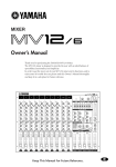
1
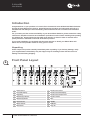
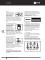
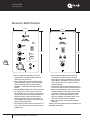
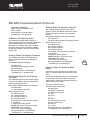
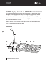
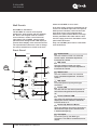
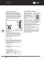
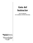
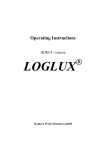
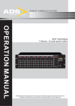
Commercial Series Q-Matrix 88 Matrix Switcher User Manual ZONE 1 ZONE 2 ZONE 3 ZONE 4 ZONE 5 ZONE 6 ZONE 7 ZONE 8 MONITOR Q-Matrix 88 MATRIX SWITCHER MIC 1 MIC 1 MIC 1 MIC MIC 11 MIC 1 MIC MIC 11 MIC 1 MIC 1 MUSIC MUSIC MUSIC MUSIC MUSIC MUSIC MUSIC MUSIC MUSIC MUSIC MASTER MASTER MASTER MASTER MASTER MASTER MASTER MASTER MASTER MASTER POWER ON OFF WARNING THIS APPLIANCE MUST BE EARTHED General Installation DO NOT run microphone cables near mains, data, telephone or 70V line cables. DO NOT run 100V line cable near data, telephone or other low voltage cables. DO NOT exceed 90% of the amplifiers output power when using 70V line (speech only). DO NOT exceed 70% of the amplifiers output power when using 70V line (high level background music). IMPORTANT The wires in the mains lead are coloured in accordance with the following code: Green and Yellow: Earth (E) Blue: Neutral (N) Brown: Live (L) If the colours of the wires in the mains lead of this device may not correspond with the coloured markings identifying the terminals in your plug, proceed as follows: If a 13 Amp (B.S.1363) plug or any other type of plug is used, a 5 Amp fuse must be fitted either into the plug or at the distribution board. DO NOT use re-entrant horn loudspeakers for background music unless the loudspeaker has been specifically designed for this purpose. AVOID jointing the microphone cable, when this is unavoidable make sure a good screened connector is used, e.g. Phono. ALWAYS use an unbalanced or floating low impedance microphone that terminates into an unbalanced input on long microphone cable runs. ALWAYS use a balanced source with a low impedance microphone that terminates into a balanced input for long line level mic/line cable runs. ALWAYS use a mains grade double insulated cable for loudspeaker cable runs. ENSURE that all loudspeakers are in-phase. ENSURE that there are no short circuits on the loudspeaker line before connecting it to the amplifier. Contents Introduction. . . . . . . . . . . . . . . . . . . . . . . . . . . . . . . . . . 4 Front Panel Layout. . . . . . . . . . . . . . . . . . . . . . . . . . . . . 4 Rear Panel Layout. . . . . . . . . . . . . . . . . . . . . . . . . . . . . 7 Remote Wall Panels. . . . . . . . . . . . . . . . . . . . . . . . . . . . 12 RS 485 Communication Protocol. . . . . . . . . . . . . . . . . . 13 Specifications . . . . . . . . . . . . . . . . . . . . . . . . . . . . . . . . 14 Connection Diagram . . . . . . . . . . . . . . . . . . . . . . . . . . . 15 QTRPS Paging Console & QTEPS Extension Panels . . . 16 QTVCS Remote Source Select/Volume Control . . . . . . 23 Q-Matrix 88 User Manual WARNING When Installing the Unit 2 User Manual • Do not expose the unit to rain or an environment where it may be exposed to water or other liquids as doing so may result in fire or electric shock. • Use the unit only with the voltage specified on the unit. Using a voltage higher than that which is specified may result in fire or electric shock. • Do not cut, kink, otherwise damage or modify the power supply cord. In addition, avoid using the power cord in close proximity to heaters, and never place heavy objects -- including the unit itself -on the power cord as doing so may result in fire or electric shock. • Be sure to replace the unit’s terminal cover once the unit has been configured. Because high voltage is applied to the speaker terminals, never touch these terminals to avoid electric shock. • Be sure to ground the unit to the safety ground (earth) terminal to avoid electric shock. Never ground the unit to a gas pipe as a catastrophic disaster may result. • Avoid installing or mounting the unit in unstable locations, such as on a rickety table or a slanted surface. Doing so may result in the unit falling, causing personal injury and/or property damage. Q-Tech Commercial Series Q-Matrix 88 When the Unit is in Use • Should the following irregularity be found during use, immediately switch off the power, disconnect the power supply plug from the AC outlet and contact your nearest Quest dealer. Make no further attempt to operate the unit in this condition as this may cause fire or electric shock. Conditions where use should immediately cease include the following: • If you detect smoke or a strong smell coming from the unit • If water or any metallic object gets into the unit • If the unit falls, or the unit case breaks • If the power supply cord is damaged (exposure of the core, disconnection, etc.) • If it is malfunctioning (no tone sounds.) • To prevent a fire or electric shock, never open or remove the unit case as there are high voltage components inside the unit. Refer all servicing to your nearest Quest dealer. • Do not place cups, bowls, or other containers of liquid or metallic objects on top of the unit. If they accidentally spill into the unit, this may cause a fire or electric shock. • Do not insert/drop metallic objects or flammable materials into the ventilation slots of the unit’s cover as this may result in fire or electric shock. Q-Matrix 88 User Manual CAUTION When Installing the Unit • Never plug in or remove the power supply plug with wet hands, as doing so may cause electric shock. • When unplugging the power supply cord, be sure to grasp the power supply plug; never pull on the cord itself. Operating the unit with a damaged power supply cord may cause a fire or electric shock. • When moving the unit, be sure to remove its power supply cord from the wall outlet. Moving the unit with the power cord connected to the outlet may cause damage to the power cord, resulting in fire or electric shock. When removing the power cord, be sure to hold its plug to pull. • Do not block the ventilation slots in the unit’s cover. Doing so may cause heat to build up inside the unit and result in fire. • Avoid installing the unit in humid or dusty locations, in locations exposed to direct sunlight, near heaters, or in locations generating sooty smoke or steam as doing otherwise may result in fire or electric shock. When the Unit is in Use • Do not place heavy objects on the unit as this may cause a fall or break the unit and\ or additional objects which may result in personal injury and\or property damage. • Make sure that the volume control is set to the minimum position before power is switched on. Loud noise produced at high volume when power is switched on can impair hearing. • Do not operate the unit for extended periods of time with the sound distorting. This is an indication of a malfunction, which in turn can cause heat to generate and result in a fire. • Contact your dealer in regards to how to correctly clean the unit. If dust is allowed to accumulate in the unit over a long period of time, a fire or damage to the unit may result. • If dust accumulates on the power supply plug or in the wall AC outlet, a fire may result. The power supply plug cleaned periodically with a dry cloth. Also ensure that the power supply plug is always securely inserted into the wall. • Switch off the power, and unplug the power supply plug from the AC outlet for safety purposes when cleaning or leaving the unit unused for 10 days or more. Doing otherwise may cause a fire or electric shock. Q-Tech Commercial Series Q-Matrix 88 3 User Manual Q-Matrix 88 User Manual Introduction Congratulations on your purchase of a new Q-Tech Commercial series Q Matrix 88 Matrix Switcher. As with all Quest Engineering devices, Quest Engineering products are engineered and built to a standard that will satisfy the most demanding users and environments of commercial installation audio. For your safety and the continued reliability of your Quest Matrix Switcher, please read all the safety instructions, amplifiers functions and installation procedures section before installing and operating the Q Matrix 88. Quest Engineering has paid great attention to detail in order to maintain strict quality assurance standards of all it’s Q-Tech Series products. If your audio installation is completed with the same attention to detail, your Matrix Mixer will deliver the its best possible results for many years to come. Unpacking Please inspect the product carefully immediately after unpacking. If you find any damage, notify your supplier/dealer immediately. Only the shipper may file a damage claim with the carrier for damage incurred during shipping. 4 Front Panel Layout 2 1 4 3 ZONE 1 ZONE 2 ZONE 3 6 5 ZONE 4 7 ZONE 5 8 ZONE 6 10 9 ZONE 7 ZONE 8 11 MONITOR Q-Matrix 88 MATRIX SWITCHER MIC 1 MIC 1 MIC 1 MIC MIC 11 MIC 1 MIC MIC 11 MIC 1 MIC 1 MUSIC MUSIC MUSIC MUSIC MUSIC MUSIC MUSIC MUSIC MUSIC MUSIC MASTER MASTER MASTER MASTER MASTER MASTER MASTER MASTER MASTER MASTER POWER ON OFF 14 13 12 15 16 User Manual 1 Select Source 9 Monitor Zone Select 2 Zone LED Display 10 Monitor Zone LED Display 3 Page Busy 11 Monitor Zone Output Level 4 MIC Priority Indicator 12 Monitor Volume 5 MIC Priority Button 13 ESC 6 Music Volume 14 ENTER 7 Master Volume 15 BGM ALL 8 MIC Volume 16 Page All Q-Tech Commercial Series Q-Matrix 88 Q-Matrix 88 User Manual 1. Source Select 4. MIC1 Priority Indicator The source select button (1) is used to select the source for the zone. Each zone has a separate source selection button. There are 9 selectable sources: Line sources 1 through 8 and a local Microphone source. The MIC1 Priority Indicator LED (4) will illuminate blue indicating the Zone MIC1 priority paging function is enabled. A different local source (remote in wall mixer or source select/volume control) can be connected to each zone. A zone cannot select the local source connected to another zone. The MIC1 Priority button (5) will enable/ disable the MIC1 priority paging function. When enabled, MIC1 will override zones 1-8 and all local inputs, if a signal is present on the MIC1 input. When disabled, MIC1 will mix with lines 1-8 and local inputs if required. Pressing the source select button will cycle through all zones in sequence: 1, 2, 3, 4, 5, 6, 7, 8, L, and OF. To select a required source, press the source select button (1). Once the display shows the desired source, press the ENTER (14) button to confirm and the change to the selected source. Note: The source will only change after the ENTER (14) button is pressed. If the ENTER (14) button is not pressed, the source selection will return to previous setting after 10 seconds. When the system is used in conjunction with remote control panels, the zone source select button will be disabled when a remote control panel is connected to a zone. In this instance, the source selection can only be controlled via the remote control panel (QT VCS or QT 1WML) In the event power is lost, the last source selection settings are automatically saved and the unit will return to its previously configured source selections when powered back on. 2. Zone LED Display The Single Digit Zone LED Display will display the selected source number: lines 1-8 and local input shown as L. 5. MIC1 Priority Button This Microphone input has been designed to give global priority over all other inputs if enabled via the front panel. The MIC1 priority setting is not saved when the Q Matrix 88 is switched off, and will return to its default state on powered back on. The default state of the MIC1 Priority is disabled. 6. Music Volume The Music Volume control knob (6) controls the selected source (zones 1-8 and local input) input level. If the system is used with Remote Control Panels, the Music Volume knob will be disabled for zones where a remote control panel is connected. Source Music Volume level will be controlled at the remote control panel only. 5 7. Master Volume The Master Volume control knob (7) will control the combined MIC1 and Source Output Volume Level, if the MIC1 input has been enabled for a zone. The Master Volume control knob will not control the Paging Console Public Address Volume Level, or the Line 8 Source Input Volume Level when the Line 8 Source Input Priority Function is enabled. This function has been designed as a global BGM input if required. 3. Page Busy The Zone Page Busy indicator LED (3) will illuminate amber to indicate a paging microphone is paging to this zone. 8. MIC1 Volume The MIC1 Volume control knob (8) will control the MIC1 input level if this global mic has been configured to operate within the zone. Q-Tech Commercial Series Q-Matrix 88 User Manual Q-Matrix 88 User Manual 9. Monitor ZONE SELECT 12. Monitor Volume The ZONE SELECT button (9) is used to select one of the 8 zones to be monitored. Pressing the zone select button will cycle through all zones in sequence as follows: 1, 2, 3, 4, 5, 6, 7, 8, and OFF. The Monitor Volume control knob (12) will control the in-built Monitor Speaker volume level. A zone can be selected pressing the ZONE SELECT button. Once the display shows the desired zone, press the ENTER button to confirm and change to the selected zone. The ESC button (13) is used to cancel the selection of source select, monitor zone select and BGM function buttons. Note: The zone will only change after the ENTER button is pressed, otherwise the source selection will be returned to its previous setting after 10 seconds. The monitor zone function enables the audio output from a zone to be monitored through a small speaker on the front panel. This is particularly useful when controlling the audio in a remote zone or testing the system. 10. Monitor Zone LED Display 6 14. ENTER The ENTER button (14) is used to confirm selection of source select, monitor zone select and BGM function buttons. 15. BGM ALL The BGM ALL button (15) is used to select the same source for all 8 zones simultaneously. To confirm the BGM ALL selection, press ENTER. The Single Digit Monitor Zone LED Display (10) will display the selected zone numbers, 1-8. Note: The BGM ALL selection will only be confirmed after the ENTER button is pressed, otherwise the source selection will be return to previous setting after 10 seconds. 11. Monitor Zone Output Level In the event power is lost, the BGM ALL selection settings will be saved and the unit will return to the previous BGM ALL setting when powered back on. The 5 LED Monitor Zone Output Level Meter (11) will provide visual indication of the audio signal level for a selected zone. User Manual 13. ESC Q-Tech Commercial Series Q-Matrix 88 Q-Matrix 88 User Manual Rear Panel Layout Quest Engineering have designed the Q Matrix 88 to provide maximum flexibility in terms of supporting several types of inputs which may be required in an installation. The Q Matrix 88 features a bank of 8 line level inputs, a mixture of 4 phono inputs and four additional inputs which are configurable as either mic or line with phantom power available. 1 2 3 4 5 7 6 8 9 10 11 12 14 13 24 15 16 17 18 19 20 1 Dip Switches 9 LF Bass 17 Line Inputs 2 EVAC / Fire System Interface 10 Output 18 Paging Console Inputs 3 Tone Output 11 Gain 19 Paging MIC Gain 4 EMC Input 12 HF 20 MIC 1 Input 5 Extension Link 13 Enable/Disable Switch 21 MIC 1 Gain 6 Remote Source 14 Remote Source Gain 22 MIC 1 Bass 7 Remote Control Input 15 Fire Alarm 23 MIC 1 HF 8 Page 16 Line Gain 1. Dip Switches Dip switches set the Matrix system address. If the system is to be expanded, each Q Matrix unit must be defined as Master, Slave 1, 2 or 3. If you are expanding the system, only line inputs 1-8, MIC1 and 2 x Remote Paging Consoles of the Master Matrix are enabled. All Slave Matrix units connected to the Master will use the Master Matrix inputs. For the avoidance of doubt, if a Matrix unit is configured as a slave, the slave Matrix Inputs 1 – 8, MIC1 and remote paging consoles inputs will be disabled. However, the optional wall plates (QTVCS and QT1WML) can be used to operate these additional zones. 21 22 7 Dip switch settings are as follows for configuring the Q Matrix 88 as a Master or Slave: Master Matrix Extension Matrix 1 Extension Matrix 2 Extension Matrix 3 Q-Tech Commercial Series Q-Matrix 88 User Manual Q-Matrix 88 User Manual PIN 1 - [+24V DC 24V] Power supply input. (Battery Back Up or UPS) PIN 2 - [GROUND DC 24V] Power supply input. (Battery Back Up or UPS) The Matrix can be linked with a DB37 Cable. This will enable the Line 1 – 8 Sources, MIC1 Input, Paging Consoles 1 & 2, and Communication Data of the master unit to be shared with any Slave Matrix Units connected to the system. PIN3 - [COMMON], Which is Common for ALERT & EVAC PIN 4 - [ALERT DRY CONTACT] The built-in alert voice message will be broadcast to all 8 zones after triggered by dry contact between ALERT and COMMON. 8 PIN 6 - [EMC IN] An optional external voice alarm message may be broadcasted to all 8 zones of the system, when an alarm signal is detected from an external voice message generator. Fire alarm, alert, EVAC and EMC in are of equivalent priority 3. Tone Output The Tone Output Volume Control will adjust the output level of the FIRE ALARM, ALERT, EVAC voice messaging. 4. EMC Input The EMC INPUT Volume control will adjust the output level of the EMC voice messaging. Fire alarm, ALERT, EVAC and EMC in are of equivalent priority 5. Extension Link (DB37 Connector) The extension link connectors enable 8 zone Matrix units to be connected together to form a larger system. Up to four 8 Zone Matrix units can be connected to make a 32 zone system. DB37 PIN 5 - [EVAC DRY CONTACT] The built-in EVAC voice message will be broadcasted to all 8 zones after being triggered by dry contact between EVAC and COMMON. 1 2 3 4 5 6 7 8 9 10 11 12 13 14 15 16 17 18 19 20 21 22 23 24 25 26 27 28 29 30 31 32 33 34 35 36 37 38 LINE 1+ LINE 1LINE 2+ LINE 2LINE 3+ LINE 3LINE 4+ LINE 4LINE 5+ LINE 5LINE 6+ LINE 6LINE 7+ LINE 7LINE 8+ LINE 8MIC + MIC PAGE 1+ PAGE 1PAGE 2+ PAGE 2PAGE 3+ PAGE 3PAGE 4+ PAGE 4GND B A GND 1 2 3 4 5 6 7 8 9 10 11 12 13 14 15 16 17 18 19 20 21 22 23 24 25 26 27 28 29 30 31 32 33 34 35 36 37 38 6. Remote Source Each zone can have a remote line level source connected. The remote source input connector is shown here. This has been designed to be used if you don’t wish to use a local in wall mixer. This could be for example, a Radio MIC. On selecting this input via the front panel controls, select “L”. Please note that this input cannot be distributed to other zones. User Manual Q-Tech Commercial Series Q-Matrix 88 DB37 2. EVAC / Fire System Interface (7 Way Pheonix Connector) Q-Matrix 88 User Manual Local zone source level has three adjustments, namely: a. Gain control for the local source Input on the rear of the Matrix b. A Music level control on the Matrix front panel or the remote wall control c. A Master level control on the Matrix front panel. Please Note: The input signal is set at 300mV-1.1v/10K Ohm 7. Remote Control Panel Input Each of the eight zones can have a remote control panel connected. The Remote control Panel will enable the source and volume to be controlled from a remote location. Each zone has its own RJ45 input connector allowing for a Remote Control Panel to be connected for control over each zone. Local Source Connections are as follows: 1. A remote wall panel can be connected to the Matrix, with only one remote wall controller able to be connected per zone. 2. The remote wall panel will be selectable on the system. Therefore, selectable sources will be L (local) as well as source line1 to 8. The RJ45 pin assignment is as follows: 8. Page The Zone Page Output Volume Control will adjust the output paging level for the Zone. Every Zone has a Page Output Volume Control which enables the paging level of each zone to be set independently of other zones. 9. LF Bass The Zone LF Bass of the Zone Output can be controlled by adjusting the LF Bass Level Control. This Level Control will provide adjustment of the 100Hz Audio Frequency by ±10dB. Every Zone has a LF Bass Level Control which enables the LF Bass Level of each zone to be set independently of other zones. 10. Output Every Zone has an AUDIO OUTPUT connector; this should be connected to the Audio Amplifier for the designated Audio Zone. 9 Zone Audio Output Connections are as labeled. 1. RS485 B 11. Gain 2. RS485 A The Zone Gain control will set the maximum Source Output Volume Level for the Zone. 3. GND 4. 24V (OUT) 5. GND This will ensure the user cannot adjust the Audio Level too high using the Master, MIC1 and Music Level Control Knobs on the Front Panel. Gain will set the Maximum Output Volume of Line Source and MIC1. It will have no control over the Paging Level. 6. + 24V (OUT) 7. SPARE 8. SPAR 1 2 3 4 5 6 7 8 Q-Tech Commercial Series Q-Matrix 88 User Manual Q-Matrix 88 User Manual 12. HF The Zone HF Treble of the Zone Output can be controlled by adjusting the HF Treble Level Control. This Level Control will provide adjustment of the 100Hz Audio Frequency by ±10dB. Every Zone has a HF Treble Level Control which enables the HF Treble Level of each zone to be set independently of other zones. 13. Enable/Disable Switch 10 If a Zone Remote Wall Control Panel is to be used with the System, The RJ45 Remote Control Panel Input needs to be enabled. The RJ45 Remote Control Panel Input is enabled / disabled by pressing the Enable / Disable Switch. Every Zone has an RJ45 Remote Control Panel Input Enable / Disable Switch. Fire alarm, alert, EVAC and EMC in are of equivalent priority. 16. Line Gain The System Line Source Input Signal Levels can be adjusted from 190mV to 200mV using the Line Source Input Gain control. This will enable the signal level of all sources to be equalized thereby ensuring Output Volume Level remains constant when switching from one source to another source. All system source inputs L(lines 1-8) have a separate Gain Control. 17. Line Inputs NOTE: Only Enable when a Zone Remote Wall Control Panel is connected. The system has 4 Line Inputs, as well as 4 inputs selectable as mic or line with phantom power available. 14. Remote Source Gain Every Line Source Input has a dual RCA Phono Connector, which will enable a Stereo Source Signal to be connected. Note, however, this is a Mono system and a Stereo Input will be combined to give a Mono Output. The Zone Local Source Input Signal Level can be adjusted from 190mV to 200mV using the Remote Source Gain control. This will enable the signal level of all sources to be equalized thereby ensuring Output Volume Level remains constant when switching from one source to another source. Every Zone Remote Source Input has a Gain Control. 15. Fire Alarm There are Fire Alarm dry contacts for zones 1-8. When Dry Contact is detected the EMC Input will be open and take priority over all other inputs. User Manual The EMC Input will only take priority and broadcast to zones where there is a Zone Fire Alarm Dry Contact Closure. Each zone has a separate Fire Alarm Dry Contact. Q-Tech Commercial Series Q-Matrix 88 Q-Matrix 88 User Manual The Line Inputs have an impedance of 47k ohms. 1. Line 1-8 source inputs will be selectable using the Source Select control on the front of the Matrix. 2) 2. The selected source input number will be indicated on the Matrix zone display. 3. Any extension Matrix unit connected to the system will use sources line 1-8 from the master Matrix. 4. Only one set of input sources for lines 1 -8 can will be connected per system. The balanced MIC1 input XLR type has an impedance of 600ohms. Each zone has a MIC1 Priority Button. Each zone has a MIC1 priority button. When the MIC1 priority button is not enabled, MIC1 will be mixed with the line inputs on each zone (1-8 or L). When the MIC1 priority button is enabled, MIC1 will take priority over all line inputs (1 - 8 or L) as well the wall control panel for that zone. MIC1 will have priority only on Zones where the MIC1 Priority Switch is enabled on the front panel. Zones where the MIC1 priority switch is not enabled, MIC1 will mix with the Source Selected for the Zone. 18. Paging Console Inputs Up to two paging consoles can be connected to the system simultaneously via the two paging console RJ45 input ports. The MIC1 level will be controlled by the MIC1 Level Adjustment Knob and the Master Level Adjustment Knob. The MIC1 signal will be sent to any extension Matrix connected to the system. The paging consoles will have equal priority and will operate on a first come first served basis. The RJ45 pin assignment order is as below: 1. RS485 B 2. RS485 A 3. GND 4. + 24V (OUT) 5. GND 6. + 24V (OUT) 7. MIC IN + 8. MIC IN – 20. MIC1 Input 11 1 2 3 4 5 6 7 8 21. MIC1 Gain The MIC1 Gain controls the MIC1 range from 5mV to 300mV. 19. Paging MIC Gain The Paging MIC Gain control will adjust the Paging MIC Input Signal Level. Each Paging MIC will have its own gain control. Thereby each Paging MIC can be set independently of the other Paging MICs. 22. MIC1 Bass The MIC1 Bass controls the MIC1 gain at 100hz (±10dB). Q-Tech Commercial Series Q-Matrix 88 User Manual Q-Matrix 88 User Manual Remote Wall Panels 86mm 86mm 146mm 146mm 12 • Up to 8 x Remote wall panels can be connected to a single Q Matrix 88 unit (with only one per zone). • There are 2 types of remote wall control panel available: QTVCS - which includes source select/Volume Control and the QTIWML - which has both MIC and Line inputs. • The QT1WML enables the source selection for a zone, zone source level control of the Q Matrix 88, connection of a local line source, connection of a local microphone and the mixing of the local line source with the local mic source. The output of the QT1WML connects to the Zone Local Input of the Q Matrix 88. • The QTVCS enables source selection for a zone, and zone source level control of the Q Matrix 88. User Manual Q-Tech Commercial Series Q-Matrix 88 • When a Remote Wall Control Panel is connected to a Zone Remote Control Input and the input is enabled on the rear of the Matrix, the Matrix zone front panel music level and source select functions will be disabled. • The Remote Wall Control Panel will have control over source select and music level. • MIC1 level and Master level controls will remain enabled on the Matrix Front Panel at all times. When a remote wall control panel is connected but disabled on the rear of the Matrix, the Matrix music level and source select will be enabled. • MIC1 and master volume will be always effective . Please note that optional black wall plates are available if required. Q-Matrix 88 User Manual RS 485 Communication Protocol Baud Rate: 57600bps/S Parity Check: Odd parity check Data: 16 bytes Accumulation = 2nd data byte + 3rd data byte + 4th data byte Q Matrix 88 Inquiry Data The Q Matrix 88 sends inquiry data to 2 remote paging consoles, 8 remote wall panels and extension Matrix. The new data will feedback to the Matrix when any new data has been checked. Any extension Q Matrix 88 will only enquire to its own 8 remote wall panels only. Inquiry Data To Paging Console The Q Matrix 88 sends the inquiry data to remote paging consoles in the following format: AA 10 00 00 AM (accumulation) AA: data head 10: inquiry to the paging console 00: meaningless AM: (accumulation = 2nd data byte + 3rd data byte + 4th data byte) Feedback Data From Paging Console The feedback data from the remote paging console to the Matrix after got inquiry and ready for paging format as: AA 11 Matrix address code zone data AM AA: data head 11: zone paging command Matrix address code: 01 : master matrix, 02 : extension matrix 1 03 : extension matrix 2 04 : extension matrix 3 zone data: the zone data is in 8 bytes 0 : no paging 1 : paging, ie: binary system 00000011B : zone1 and zone 2 paging 00000100B : zone 3 paging 11111111B : all 8 zone paging AM: (accumulation = 2nd data byte + 3rd data byte + 4th data byte) Status Data To Paging Console After getting paging data from the remote paging console, the Matrix sends zone status data to the paging console in the following format: AA 1E Matrix address code zone data AM AA: data head 1E: Zone status feedback to paging console Matrix address code: 01: master matrix 02: extension matrix 1 03: extension matrix 2 04: extension matrix 3 zone data: the zone data is in 8 bytes, 0: no paging 1:paging, ie: binary system 00000011B:zone1 and zone 2 busy 0000100B: zone 3 busy, 11111111B: all 8 zone busy AM: (accumulation = 2nd data byte + 3rd data byte + 4th data byte) 13 Inquiry Data To Remote Wall Plate If the zone is not controlled by a remote wall plate, the inquiry data will not be sent to this zone. The inquiry command which is from the Matrix to the remote wall plate is both inquiry and status data to update the wall plate status, ie: source input, zone volume. The inquiry data format is: AA 20 line input volume AM AA: data head 20: inquiry to wall plate line input: source input 01 : line 1 02 : line 2 .......... 08 : line 8 09 : remote sources input volume: volume level 00 : 0 level 01 : 1 level AM: (accumulation = 2nd data byte + 3rd data byte + 4th data byte) Q-Tech Commercial Series Q-Matrix 88 User Manual Q-Matrix 88 User Manual Feedback Data From The Wall Plate Inquiry Data To Extension Matrix The feedback data from the wall plate to the Matrix delivered in the following format: The Matrix inquiry data to the extension Matrix format as: AA 21 line input volume AM AA 30 00 00 AM AA: data head 21: feedback data from wall plate to Matrix line input: source input 01 : line 1 02 : line 2 .......... 08 : line 8 09 : remote sources input volume: volume level 00 : 0 level 01 : 1 level AM: (accumulation= 2nd data byte + 3rd data byte + 4th data byte) 14 Specifications Deviation AC Power Supply Conditions Voltage selector between 115V & 230V DC Power Supply Line Input Sensitivity +24V Clockwise rotation gain to increase Line Input Impedance Local Input Sensitivity 500mV ±8dB Clockwise rotation gain to increase 600Ω MIC1 Impedance MIC Level Control Input 100Hz sine wave signal Paging Console Sensitivity Input 1KHz sine wave signal & output 0.775V 500mV Paging Console Gain Control Zone Output ±8dB ±8dB Balanced output Zone Gain Control 0.775V ±8dB Zone Output Level Control Input 100Hz sine wave signal ±10dB S/N Ratio Non-weighting <60dB Isolation Degree >40dB Channel Crosstalk User Manual 195mV-2.0V 47KΩ Balanced input Local Gain MIC1 Sensitivity Parameters >50dB Gain Deviation 20Hz-20KHz <2dB T.H.D 20Hz-20KHz <0.07% Channel Phase Position 20Hz-20KHz Same phase Frequency Response Line1-8 inputs and remote source input, 20Hz-20KHz +1/-3dB Frequency Response MIC1 input, 80Hz-18KHz +1/-3dB Q-Tech Commercial Series Q-Matrix 88 Deviation AC 115V/AC 230V; 50Hz/60Hz 10% ±4V Q-Matrix 88 User Manual Connection Diagram MIC Input 1 8 Remote Control Panels Line 1-8 Inputs ZONE 1 ZONE 2 ZONE 3 ZONE 4 ZONE 5 ZONE 6 ZONE 7 ZONE 8 1-8 Zone Speaker Outputs MONITOR Q-Matrix 88 MATRIX SWITCHER MIC 1 MIC 1 MIC 1 MIC MIC 11 MIC 1 MIC MIC 11 MIC 1 MIC 1 MUSIC MUSIC MUSIC MUSIC MUSIC MUSIC MUSIC MUSIC MUSIC MUSIC MASTER MASTER MASTER MASTER MASTER MASTER MASTER MASTER MASTER MASTER POWER ON OFF Master Matrix Link 8 Remote Control Panels Paging MIC 1 ZONE 1 ZONE 2 ZONE 3 ZONE 4 ZONE 5 ZONE 6 ZONE 7 ZONE 8 9-16 Zone Speaker Outputs MONITOR Q-Matrix 88 MATRIX SWITCHER MIC 1 MIC 1 MIC 1 MIC MIC 11 MIC 1 MIC MIC 11 MIC 1 MIC 1 MUSIC MUSIC MUSIC MUSIC MUSIC MUSIC MUSIC MUSIC MUSIC MUSIC 15 POWER ON OFF MASTER MASTER MASTER MASTER MASTER MASTER MASTER MASTER MASTER MASTER Extension Matrix 1 Link Paging MIC 2 8 Remote Control Panels ZONE 1 ZONE 2 ZONE 3 ZONE 4 ZONE 5 ZONE 6 ZONE 7 ZONE 8 17-24 Zone Speaker Outputs MONITOR Q-Matrix 88 MATRIX SWITCHER MIC 1 MIC 1 MIC 1 MIC MIC 11 MIC 1 MIC MIC 11 MIC 1 MIC 1 MUSIC MUSIC MUSIC MUSIC MUSIC MUSIC MUSIC MUSIC MUSIC MUSIC MASTER MASTER MASTER MASTER MASTER MASTER MASTER MASTER MASTER MASTER POWER ON OFF Link Extension Matrix 2 8 Remote Control Panels ZONE 1 ZONE 2 ZONE 3 ZONE 4 ZONE 5 ZONE 6 ZONE 7 ZONE 8 25-32 Zone Speaker Outputs MONITOR Q-Matrix 88 MATRIX SWITCHER MIC 1 MIC 1 MIC 1 MIC MIC 11 MIC 1 MIC MIC 11 MIC 1 MIC 1 MUSIC MUSIC MUSIC MUSIC MUSIC MUSIC MUSIC MUSIC MUSIC MUSIC MASTER MASTER MASTER MASTER MASTER MASTER MASTER MASTER MASTER MASTER POWER ON OFF Extension Matrix 3 Q-Tech Commercial Series Q-Matrix 88 User Manual Q-Matrix 88 User Manual QTRPS Paging Console & QTEPS Extension Panels The remote paging console can work together with the Matrix to set up a 32 zone paging system. Each Matrix can accommodate 2 remote paging consoles which may be identified by dipswitch settings. Each remote paging console is designed for an eight zone paging capacity, while an extension keypad may be added where more than 8 zones (and up to 32 zones of paging) is required. A maximum of 3 extension keypads may also be added. The communication between the Matrix 88 and the remote paging console is achieved via industry standard CAT5 cable which is also used to provide the DC24V power to the paging console when the communication distance is < 50 meters. For distances of more than 50 meters, communication requires the addition of a DC24V power supply to the paging console through the power input on the rear of the remote paging console. 2 or 4 tone selectable pre-announce chimes are built-in for use before announcements. A no chime option is also available by turning the option OFF. Front Panel 16 5 1 6 7 8 9 User Manual 10 11 12 13 Q-Tech Commercial Series Q-Matrix 88 14 2 3 4 Q-Matrix 88 User Manual 1 Master Remote Paging Console 10 2 Extension Keypad 1 3 Extension Keypad 2 4 Extension Keypad 3 5 Gooseneck Microphone 6 Power Indicator The All Call Button can be selected when all zones are to be selected. If more than one console is being used, priority operates on this is on a “first in first served” basis. The All Call indicator will be turned off when the All Call button is pushed and the other paging consoles are in use. The busy indicator will turn amber and flash if the other console is paging into any particular zone. In this case, it may be possible to page zones that are not showing up as busy. The LED indicator light will appear blue when the power switch is in the on position. The light will turn off when the power switch is placed at off position. 7 Output Level Meter A 5 position LED output level meter displays the output level status, (green, green, green, amber, red) 8 Talk Indicator The LED will turn blue when the talk button is pushed, and will turn off when talk button is released. 9 Talk Button After selecting a zone, an announcement can be made when the talk button is pressed and the indicator is illuminated. Without zone selection, an announcement cannot be made, even when the talk button is pushed. In this instance, the indicator light will flash and turn off. 11 All Call Button All Call Indicator The LED will be show blue when the All Call button is pushed, which will turn off when the All Call button is released. 12 Zone Label 13 Zone Indicator Dual colour indicator LEDs are used to display the zone status. The indicator will be blue under paging status and amber under busy status. 14 Zone Select Button Push the zone select button to page a zone. After the button is selected, the zone indicator will slowly flash if the com ports are busy and change to amber. Communication is only available if the blue LED shows Q-Tech Commercial Series Q-Matrix 88 17 User Manual Q-Matrix 88 User Manual Rear Panel POWER 24VDC CCM 15 15 2TOME OFF 4TOME 16 Power Switch The paging console is powered from the Matrix through CAT5 cable as long as the communication distance is < 50 meters 16 18 DC 24V Power Input An additional DC24V power supply is required if the distance from the paging console and Matrix is greater than 50m 17 Communication Port The communication port is an RJ45 Socket to the Matrix which uses standard Cat 5 cable User Manual Q-Tech Commercial Series Q-Matrix 88 CHIME SELECT MIC VOL CHIME VOL on off 17 18 18 19 20 MIC Volume Control This control is used to adjust the microphone output volume. Clockwise adjustment increases the level. 19 Chime Volume Control This is used to adjust the chime volume. Clockwise adjustment increases the level 20 Chime Selector This selector has three options for the pre-announce chime: 2 tone, 4 tones and OFF Q-Matrix 88 User Manual Connection and Setting Power Supply The remote paging console is powered by the Matrix through the RJ45 communication port when the communication distance is < 50 meters. An extra DC 24V power input is equipped on the back part of the paging console to supply power when the communication distance is longer than 50 meters. Connection Between Remote Paging Console & Extension Keypad The IDE communication cable is used to provide connection between the remote paging console and the extension keypad as well as between two extension keypads. Connection Through 10P IDE Cable Extension Keypad Remote Paging Console 19 Extension Keypad Dip Switch Setting 1 2 3 4 1 2 3 4 1 2 3 4 Extension Keypad 1 Extension Keypad 3 Extension Keypad 2 There are 4 address codes on both remote the paging console and the extension keypad which are used to identify these. Please Note: Only one address code switch of each dip switch can be placed in the downward position. If any of the dip switches are set at different addresses to those shown above, the console will not operate. Extension keypad Remote paging Console Connection is made through the supplied 10P IDE cable. Once either two or three QTEP extension panels are connected, the operation of paging announcements is the same as described previously for individual zone paging or all call actions. Q-Tech Commercial Series Q-Matrix 88 User Manual Q-Matrix 88 User Manual Wall Panels where the QT1WML is to be used. A ten step volume control is provided over all sources. A dual RCA input and a microphone XLR input are included, each with their own input level control. The communication between the panel and the Matrix is through industry standard CAT5 cable which is also used to supply power from the Matrix to this panel within 50 meters. QT1WML In-wall Mixer The QT1WML is a remote control panel designed to work together with the Q Matrix 88. This in turn may be used as a remote source selector, volume control and local input panel. The QT1WML remote control panel has been designed with LED display to provide direct display of the selected sources. The up and down buttons are used to change the source material to be routed to the zone Only one QT1WML panel can be used within each Audio Zone. Front Panel 1 86mm Source Level Ten level volume control over selected source output. Clockwise adjustment increases the volume 2 20 5 1 6 3 4 7 3 8 MIC Input Local microphone input by XLR type connector 5 4 Music Level Ten level volume control over local line input. Clockwise adjustment increases volume 146mm 2 MIC Level Ten level volume control over local microphone input. Clockwise adjustment increases the volume Power LED The LED will turn blue when powered on and will be extinguished when powered off 6 Source Channel LED The white LED with blue background will display the source channel 1-8 with the local line level as ‘L’ 7 Source Up & Source Down These two buttons are used to increase or decrease the input source channel from 1-8 and local input (L) 8 Line Input Local line input by dual RCA type connector. This will be summed as mono output User Manual Q-Tech Commercial Series Q-Matrix 88 Q-Matrix 88 User Manual Connection & Wiring Power Supply 9 10 13 11 The RJ45 port is used to communicate between the remote control panel and the Matrix, it also will be used to supply power to the panel within 50 meters. A spare DC24V input is provided for extra power supply to the remote control for communication distances longer than 50 meters. The communication cable preferred is industry standard CAT5 cable. Local Source Input 12 14 The local source input through the dual RCA aux input connector. Microphone Input The 3 pins of the mic input at the rear side are sent to the PCB board through the microphone signal input. Spare AUX Output To AMP 10 Spare 24V DC Input Extra DC 24V will be needed to power supply the remote control 11 RJ45 Communication Port The RJ45 port is used to communicate between the remote Control panel and the Matrix. I also supplies power to remote panels within 50 meters 12 MIC Connector 13 JTAG Connector It is used to burn program 14 MIC Signal Input 21 Aux Output Aux output is included in the RJ45 communication port. A spare aux output is also provided. Spare AUX Output & Spare 24V DC Input When the communication distance is longer than 50 meters, this connection can be used for additional power. A second run of Cat 5 may be used. +24V2 GND GND Audio Audio + GND 1 2 3 4 5 6 9 Connector to input microphone signal to the PCB board Q-Tech Commercial Series Q-Matrix 88 User Manual Q-Matrix 88 User Manual Operation Power Supply The remote control panel will have active power via CAT 5 cable from the Q Matrix 88, over distances <50 meters or an external 24v supply if the distance is over 50 meters. The power indicator will turn blue, which will be as a status indicator to display the active communication between the wall panel and the Q Matrix 88. Source Selection A total of 9 sources including lines 1-8 and local input (L) can be selected on the panel using the SOURCE UP and SOURCE DOWN buttons. The selected source will be displayed on the LED. Volume Control 22 A ten step volume control is provided for each input which includes source, local line and local microphone. Specifications Communication Speed 5/500bps Communication Distance <_1km MIC Input 335MV AUX Input 775MV S/N Ratio MIC: 255 dB BGM: 2/5dB TFD User Manual Power Supply DC 24V Weight 153g Dimensions W x D x H 55mm x 14mm x 33mm Q-Tech Commercial Series Q-Matrix 88 Q-Matrix 88 User Manual QTVCS Remote Source Select/Volume Control The QTVCS is a remote control panel designed to work together with Q Matrix 88. The QTVCS is suitable for use as a remote source selector and a volume controller for signals fed into the zone via the Q Matrix 88. The remote control panel is designed with an LED to provide direct display of the selected sources, with up and down buttons to be used for changing source material from the Q Matrix 88. A ten level volume control is provided for control over the selected source. Communication between the panel and the Matrix is achieved via industry standard CAT5 cable which also is used to supply power from the Matrix to this panel when the distance is < 50 meters. A total of 8 remote control panels can be used with each Matrix unit. Front and Rear Panels 86mm 1 Source Channel LED The white LED with a blue background displays the source channel 1 to 8 and local input as ‘L’. 2 Source Level Ten level volume control over selected source output. Clockwise adjustment increases the volume 23 1 146mm 2 3 JTAG Connector Is used to burn program information. 3 4 Spare 24V DC Input An extra DC 24V is provided to power the remote control panel if the communication distance is longer than 50 meters. 4 5 5 RJ45 Communication Port The RJ45 port is used to communicate between the remote control panel and the Matrix. It also will be used to power supply. It also supplies power to the panel within 50 meters. Q-Tech Commercial Series Q-Matrix 88 User Manual Q-Matrix 88 User Manual Connection & Wiring 1 2 The RJ45 port is used to communicate between the remote control panel and the Matrix, it also will be used to supply power to the panel within 50 meters. A spare DC24V input is provided for extra power supply to the remote control for communication distances longer than 50 meters. The communication cable preferred is industry standard CAT5 cable. 485 - B 485 - A RE D GND 24V1 24V1 NC NC Spare 24v input RJ45 Com port GND 24 +24V2 1 2 3 4 5 6 7 8 Operation The remote control panel is powered from the Q Matrix 88 if the distance is < 50 meters or less. The power indicator will turn blue which acts as a status indicator to display. Remote Control Panel and the Matrix are communicating. Source Selection A Total of 9 sources are available (inputs 1-8 and local input (L)) that can be selected on the panel using the SOURCE UP and SOURCE DOWN buttons. The selected source will be displayed on the LED. Volume Control A ten step volume control is provided for the local zone input. Specifications Communication Speed User Manual 57600bps Communication Distance <_1km Power Supply DC 24V Weight 73g Q-Tech Commercial Series Q-Matrix 88 Installation Notes If there are any problems with the gain structure, and feel there is too much hiss coming from the speakers within the zone/s adjustments of the GAIN, HF and LF controls may be required. For each zone where they may be an issue, check that the HF and LF adjustments on the rear panel are at unity. There are separate controls for Paging, Gain as well as HF and LF. As a point of reference, adjust both the HF and LF so that the symbol ‘EDS’ is at the 9.00 position as shown here. From this point, it is a simple matter of adjusting both the HF and LF to gain the best balance of signal to noise. The level controls on the Q Matrix 88 operate in 2db steps. It is advisable to make volume adjustments slowly in order to avoid large jumps in audio signal. www.questaudio.net Quest Engineering Pty Ltd 86 Derby St. Pascoe Vale VIC 3055 Ph 613 9354 9133 | Fax 613 9354 9233