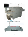
1
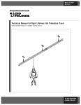
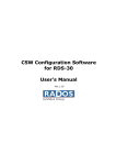
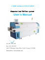
OMXIE-SMTmax CORPORATION
Computer
omputerized
ized Reflow system
User’s Manual
Tel: (951) 543-4543
Fax: (951) 582-9422
Add: 125 Business Center Drive, Unit G, Corona, CA 92880
Email address: [email protected]
Disclaimer
SMTmax/Omxie Corp. shall not be liable in contact, tort, or otherwise, for any loss or
damage suffered by the purchaser(s) whatsoever or whosoever arising out of, or in
connection with, the use of this equipment, other then, at the option of SMTmax/Omxie
Corp., to refund the purchaser money in respect of the equipment if purchaser(s) returns
equipment in unused, resalable condition, after having obtained written approval to do
so from SMTmax/Omxie Corp.
Any use of the oven not explicitly described in this manual is strongly advised against
and will void purchaser’s warranty.
Equipment is not suitable for heating food, liquids or tissue.
Equipment must not be used in the vicinity of children, animals or unqualified people.
CONTENT
1. Equipment general knowledge
2. Equipment setting
3. Equipment operating instruction
4. Lead-free techniques recommend
5. Specification and Heat Zone mount
6. Equipment Maintenance
1. Equipment general knowledge
1.1 Heating principles:
1.1.1 Heater modality:
modality The two types of heating elements are
general heating-rays (convection) and infrared-rays.
The main structure of the heater is loading the
1
nickel-chrome alloy heater line into metal pipe and loading
into silicate, makes the heat transfer out of the metal pipe
into the air.
Another note, the infrared ray structure is loading the
nickel-chrome alloy heater line into ceramic pipe then
loading into silicate and smearing special chemical on the
surface, it brings the infrared ray a wavelength that is
4.5um.
1.1.2 Heat up principium:
principium:
The hot air source comes through the ceramic heater,
that heats onto the PCB surface and to various SMC, SMD and
Solder Paste, Please assure the temperature distribution is
counterpoise into equipment and working area. Also, a few
infrared rays have a wavelength of 4.5um with air molecule
\PCB\SMC engender part quantity of heat.
The infrared ray that wavelength is 4.5um is best
wavelength for heating purpose.
1.1.3 Characteristic of heat transfer
transfer
1.1.3.1 The hot air comes
comes through IR heater:
·The IR heater shadows the SMD grotesque in shape at first
hand;
· It prevents partial place heat excess;
· It keeps diversified SMC\SMD\PCB heating temperature
distributing equilibrium;
·It keeps SMC\SMD\PCB lying in different places heating
temperature distributing equilibrium;
· It can also solder PCB board that are made from
multifarious material.
1.1.3.2 A few infraredinfrared-rays
rays
·IR heater will directly heat onto the PCB board, reduces
air flux;
·It reduces oxidation of the solder;
·It makes the equipment overall power sufficient;
·It makes the temperature rise at a swiftly rate;
· IR ray keep the environment clean, it can decompose
2
colophony in the solder.
1.1.4 Heat structure
1.1.4.1 Structure of Heat zone
Equipment
type
AE-R330A
AE-RF430-CF
AE-RF530-C
AE-RF530-CF
AE-RF630-C
AE-RF630-CF
AE-RF830-CF
AE-RF630-CEF
AE-RF830-CEF
Heat zone
quantity
Top heater
quantity
5
4
5
5
6
6
8
6
8
5 group
3 group
3 group
3 group
4 group
4 group
4 group
3 group
4 group
lower
heater
quantity
0 group
1 group
2 group
2 group
2 group
2 group
4 group
3 group
4 group
Startup
power
Work
power
6kw
6kw
7kw
7kw
8kw
8kw
10kw
8kw
10kw
2.5kw
2.5kw
2.5kw
2.5kw
3kw
3kw
3kw
2.5kw
3kw
1 . 1 . 4 . 2 Temperature test dot
Every last heat zone peg has a standard thermocouple test dot;
this dot is a static-state test dot which test temperature of the
heat zone. (This dot has been tested before shipment, currently
cannot shift placement if it has not been approved by the
manufacture.)
1 . 1 . 4 . 3 Temperature controller
Every last heating zone is controlled by a Temperature
controller which is buildup by hardware and software. Temperature
controller test static-state temperature dot, it has PID operation
function and SSR drive function.
2.2 The Temperature Profile
AE serials equipment is used of thawing the Soldering Paste
3
and soldering PCB and SMC\SMD component. Heating through the PCB
surface and SMC\SMD, Obtain the Temperature Profile as been
prescribed.
Our Suggested Temperature Profile by IPC as follows.
Suggested Temperature Profile
Temp.
(℃)
250
210℃
~230℃
200
A-Line
150
120℃
~150℃
100
C-Line
B-Line
50
0
30
60
90
120
ti
Line A:Is
used generally for Soldering Paste. The temperature of
A
PCB rise to 120-150℃ from room temperature in 60S, and the heat
rate under 3℃/s. The heat temperature of the PCB keeps about 150℃
in 60S~150S. Then the Soldering Paste melting point occurred, PCB board
temperature becomes balance.
4
PCB soldering: The temperature of PCB keeping 210℃-230℃
in 30S. Here Soldering Paste has been reflow sufficient.
Line B: It can be used for soldering micro-miniature distance SMD
for instance QFP and BGA.Through control temperature rise rate at
Preheating zone, delay Flux intenerated time in Soldering Paste,
It controls the micro stannum-ball heat flowing all together and
forming stannum-ball.
Line C: It is used for SMT Glue water solidifies.
The temperature of PCB keep basic constant temperature time
about 150℃ in 90S~300S.
In order to get high output at high automatic SMT line, U must
set the Temperature Profile carefully before starting your
application .And supervise must settled down to study in earnest
for the examination.
2.4
2.4 Heat zone function described
described
2.4
2.4.1 Preheating
Preheating zone
Also be named as temperature rising swift zone, is used for
preheating the PCB and vaporizing impregnate.
2.4
2.4.2 Impetuous Zone (heat
(heat preservation Zone)
The time must be set correctly for your PCB board through this
zone, Must be a constant temperature environment ,PCB and Soldering
5
Paste occur physically and chemically transformation, prepare for
soldering PCB and Soldering Paste reflowing.
2.4
2.4.3 Reflow zone
The reflow heating solder zone, hot air or infrared heater
offer abundant quantity of heat. The temperature in the reflow zone
for the top heater would be higher than bottom in order to engender
reflow on PCB top surface.
2.5
2.5 Heat zone setting
2.5.1 Set initialization of heat zone and conveyance rate
2.5.2 Preheating time (warm up) is almost 20Min-30 Min for cold
oven.
2.5.3 PCB is moved through oven as temperature has arrived a
balance,in this status Soldering Paste arrive reflow critical
temperature.
2.5.4 If reflow has not occurred, it should reduce transport rate
of stainless steel belt 5 to 10%.
Another method is to increase the setting temperature when
transport rate is invariableness. Commonly it should raise 5℃
at a time, you should pay attention to the temperature setting
of oven, and it must not exceed PCB support.
2.5.5 Temperature Profile may be adjusted basing on complexity of
PCB.
6
3. Equipment setting
3.1 Equipment setting surroundings
3.1.1 Please run equipment in clean surroundings;
3.1.2 Please avoid using equipment in high temperature or dank
environments.
3.1.3 Don’t set equipment by fountain of electromagnetism
disturbing.
3.1.4 Don’t make the reflow oven import and export toward fans or
windows which is used to ventilate room.
3.2 Notice proceeding of safety
3.2.1 Don’t put things except for work pieces into equipment.
3.2.2 Please notice high temperature, avoid to be scalded.
3.2.3 It should make the most of run equipment in normal temperature
when examine and repair equipment.
3.3 The series equipment operation surroundings
3.3.1 Environment temperature: 5-40℃ whether or not equipment is
working.
3.3.2 Relative humidity: 20%-95%.
3.3.2 Transportation and storage
The equipment may be transported and preserved in the
temperature range of -25-55℃. It can endure high temperature less
than 65℃ in a 24H period. Please try to avoid aquosity, high
7
temperature, libration, pressure, strike when it is transported
to conveyor.
3.4 Power supply Option’s
Option s
3.4.1 220V/ three Phase
3.4.2 220V/Single Phase 50/60 Hz
3.4.3 220V/ three Phase 50/60 Hz
3.5 Adjust equipment highness
highness
Adjust the equipment convection highness and level in rise
equipment feet. Adjusting method include using gradienter.
3.6 Preceding that the User would notice
3.6.1 The reflow oven must work around clean surroundings.
3.6.2 Don’t use or conserve equipment in bad surroundings for
example high temperature.
3.6.3 Don’t set equipment near fountain of electricity or
magnetism.
3.6.4 Please turn off power supply first before you try examining
or repairing oven.
3.6.5 Oven should set without incline and must keep conveyor chain
in level and prevent PCB displacement when it is carried.
3.6.6 Please prevent high temperature as working.
3.6.7 Don’t transmit work piece too large in the oven for fear
attaint net conveyor and will affect temperature stabilization。
8
4. Equipment operating:
4.1 Provision before operating
4.1.1 Check power supply.
4.1.2 Check main circuit in electricity box to be flexible.
4.1.3 Check equipment to be the grounded credibility.
4.1.4 Check eye winker whether to be in electricity box.
4.1.5 Check conveyor chain is locked by eye winker.
4.1.6 Check lubricate of axletree.
4.1.7 Check chain is lubed which can work in high temperature.
4.1.8 Check convulsions piping exterior is free.
4.1.9 Check blow motor is working in gear.
4.1.10 Check prolong-line of transducer is flexible.
4.2 Control Software Operate Method
4.2.1 Electrical source is on;
4.2.2 Equipment switch is on;
4.2.3 Start button is on;
4.2.4 Computer start-up automatic and enter the Main-interface as
following.
9
4.2.4 Press “On”, “Blower”; “Conveyor”, “Heat”, and stove
begin heat according to enactment. If Blower and Conveyor have not
communicated, stove can not work.
4.2.5 Intercalate temperature value
Press “Temp Set” button on the Main-interface, then press
SV at next interface, import temperature value and press “Save”.
10
4.2.6 Function parameter intercalate
Press “Operate”-“Sys Parameter” on Main-interface and
come out function parameter interface. The function parameter
include conveyance rate, blowers inverter, velocity of flow, value
of over temperature, temperature demarcate, delay time setting.
11
4.2.7 Temperature Profile testing
12
4.2.7.1 Prepare testing PCB, connect it and the
temperature-measuring wire and measuring connector, insert
measuring connector into the measuring receptacle.
4.2.7.2 Hold the testing PCB into oven center; make it move thru
the conveyor chain of equipment.
4.2.7.3 Press “profile” to enter the “Profiling Recipe” interface,
Press “test” to measuring the Temperature Profile.
4.2.7.3
The
Temperature
Profile
transferred.
13
can
be
saved,
printed,
5. Lead-free
techniques
recommend
LeadLead-free solder:
Alloy type
melting point
intension
ductility
ductility
SN-3.5AG-0.7CU
217-220
39
31
SN-3.1AG-1.3CU
217
50
32
SN-0.3AG-0.7CU
216-227
25
40
SN-3.0AG-0.5CU
217-221
37
33
SN-0.7CU
227
28
34
SN-3.5AG
221
43
45
SN-37PB
183
49
44
Soldering Paste
Setting Temperature Profile is based on producer of Soldering
Paste supplying.
Specification and Heat Zone set
6.1 AE series computer Reflow system ilk
6.1.1 AE-R330A
Five heat zones hot-air- infrared all on top.
6.1.2 AE-RF430-CF four heat zone hot-air
6.1.3 AE-RF530-C
five heat zone hot-air- infrared
6.1.4 AE-RF530-CF five heat zone hot-air
6.1.5 AE-RF630-C
six heat zone hot-air- infrared
14
6.1.6 AE-RF630-CF six heat zone hot-air
6.1.7 AE-RF830-CF eight heat zone hot-air
6.1.8 AE-RF830-C
eight heat zone hot-air-infrared
6.2 Five heat zone hothot-airair-infrared reflow system
AEAE-RF530RF530-C
6.2.1 Equipment type parameter depict
This type of equipment is a reflow solder system combination
of convection and infrared. It has five heat controlling zones,
include two preheating zone, two reflow solder zone, one drying
zone.
Top preheating zone and top reflow solder zone is heated by
infrared.
6.2.2 Equipment outline
Outline size: L-2000 * W-612 * H-1220
Heat zone length: 1000mm
Equipment weight: 180kg
Maximum Power: 7 kW
Working Power: 2.5 kW
Import Power supply:
AC 2ф220V single phase 50/60Hz +N+G in USA or Japan
6.2.3 Conveyor system
15
Belt width: 300MM
Conveyor height: 880±20mm
PCB size: 280×280 mm
Time of crossing stove: 3.5--5.5 Min
6.2.4 Heat zone function describes:
Heat zone NO.1: Top preheating zone, 2kw
Heat zone NO.4: Lower preheating zone, 1kw
Heat zone NO.2: Drying zone, 1kw
Heat zone NO.3: Top reflow zone, 2kw
Heat zone NO.5: Lower reflow zone, 2kw
6.3 Eight heat zone hothot-air reflow system
6.3.1 Equipment type parameter depict
This type of equipment is a reflow solder system combination
of hot air and infrared. It has five heat controlling zones, include
two preheating zones, two reflow solder zones, four drying zones.
6.3.2 Equipment outline
Outline size: L-2600 * W-612 * H-1220
Heat zone length: 1400mm
Equipment weight: 250kg
Maximum Power: 10 kW
Working Power: 3 kW
Import Power supply:
16
AC 3ф380V 50Hz +N+G in China or Argentina
AC 1ф220V single phase 50Hz +N+G in USA or Mexico
AC 2ф220V three phase 50/60Hz +N+G in USA or Japan
6.3.3 Conveyor system
Belt width: 300MM
Conveyor height: 880±20mm
PCB size: 280×280 mm
Time of crossing stove: 3.5--5.5 Min
Conveyor rate: 200--800mm/Min
6.3.4 Heat zone function describes:
Heat zone NO.1: Top preheating zone, 2kw
Heat zone NO.5: Lower preheating zone, 1kw
Heat zone NO.2: Drying zone, 1kw
Heat zone NO.3: Drying zone, 1kw
Heat zone NO.6: Drying zone, 1kw
Heat zone NO.7: Drying zone, 1kw
Heat zone NO.4: Top reflow zone, 2kw
Heat zone NO.8: Lower reflow zone, 2kw
17
Service and malfunction eliminate
7.1 Proceeding needing notice
It must be grounded on-vehicle.
Knowledgeable man must operate this equipment.
Add lube in conveyor chain once a week.
Stop work if the red light is on (warning light).
Don’t place any equipment that is combustible or explosive near
the reflow oven.
Don’t put hand or body into equipment.
Don’t
adjust
parameter
of
transducer
or
temperature
controller at random.
Add lubricate grease at least three times per month.
7.2 Maintain dayday-toto-day
7.2.1 Keep clean in electric wire.
7.2.2 Check blower whether run agile.
7.2.3 Check deviant sound from blower or motor.
7.2.4 Check conveyor system become flexible.
Before start-up, must check voltage whether it is safe and
stabilization. At the same time, check setting parameter. Don’t
stop conveyor when stove is very hot. Please clean surface of the
equipment before on duty or off duty.
7.2.5 Adding lube into axes of motor four times a within a 30 day
18
period.
7.3 Daily malfunction
7.3.1 The red lamp shines
7.3.1.1 If buzzer rings endless, check time relay before working.
7.3.1.2 Check wire of thermocouple to be cut.
7.3.1.3 Check SSR in main wire to be attainted.
7.3.2 Equipment can’t start-up
7.3.2.1 Check power supply.
7.3.2.2 Check Emergency Stop button.
7.3.3 Transport system can’t run
7.3.3.1 Check transducer power supply.
7.3.3.2 Check transducer communication.
7.3.3.3 Check transport motor.
7.3.3.3 Check transport belt to be blocked.
7.3.4 Can’t heat
7.3.4.1 Check “Off/On”, “Blower”, “Conveyor” button to be
pressed.
7.3.4.2 Check “Heat” button to be turned on.
7.3.4.3 Check if the switch which control SSR has been closed.
7.3.4.4 The SSR is not to be mangled.
19
AE-R530C Five Zone Reflow Oven. (Computer is optional)
AE-R330A Desktop Five Zone Reflow Oven.
20