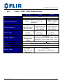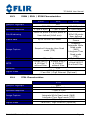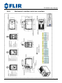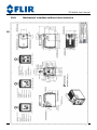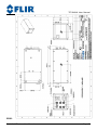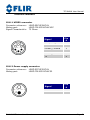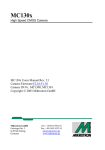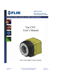
1
FLIR Systems Advanced Thermal Solutions DC019U-F TITANIUM User Manual TITANIUM User Manual TITANIUM User Manual PAGE LEFT INTENTIONNALY BLANK DCO19U-F Titanium User Manual Page 2 TITANIUM User Manual 1. Contents 1. 2. 3. 4. Contents ..............................................................................................3 For your safety.....................................................................................4 Precautions ..........................................................................................5 General Overview.................................................................................6 5. Starting with the camera .....................................................................9 6. Using your camera .............................................................................13 7. Maintenance ......................................................................................19 8. Accessories ........................................................................................20 9. Diagnostics ........................................................................................21 4.1. Product Overview ............................................................................................ 6 4.2. Packing Contents ............................................................................................ 6 Camera description ................................................................................................. 8 5.1. 5.2. 5.3. 5.4. 5.5. 5.6. 5.7. 5.8. Mounting the camera ..................................................................................... 10 Installation of the software on the computer ..................................................... 10 Connecting the camera .................................................................................. 10 Powering the camera ..................................................................................... 10 Pointing and focusing..................................................................................... 11 Camera Power Off ......................................................................................... 11 Precautions .................................................................................................. 11 Training ....................................................................................................... 12 6.1. Changing the lens ......................................................................................... 13 6.2. Removing the lens interface ........................................................................... 14 6.3. Filter wheel .................................................................................................. 15 6.3.1. Inserting / removing a filter on the optional filter wheel ............................. 16 6.4. Lockin connection (Optional) .......................................................................... 18 7.1. Cleaning optical surfaces ................................................................................ 19 7.2. Storing ........................................................................................................ 19 8.1. 8.2. 8.3. 8.4. 8.5. Additional lenses ........................................................................................... 20 Long cables .................................................................................................. 20 Interconnection / transformation cases ............................................................ 20 Tripods / pan & tilt ........................................................................................ 20 Filters .......................................................................................................... 20 9.1. Diagnostic table ............................................................................................ 21 9.2. How to contact after sales service? .................................................................. 23 10. Technical data ....................................................................................24 10.1. Common Characteristics ................................................................................ 24 10.2. 520M / 550M / 560M Characteristics................................................................ 25 10.3. 530M / 530L / 570M Characteristics ................................................................ 26 10.4. 570L Characteristics ...................................................................................... 26 10.5. Mechanical interface with lens interface ........................................................... 27 10.6. Mechanical interface without lens interface ....................................................... 28 10.7. Electrical interface ......................................................................................... 30 10.7.1. VIDEO connector ................................................................................... 30 10.7.2. Power supply connector ......................................................................... 30 10.7.3. Trigger connector .................................................................................. 31 10.7.4. Lockin connector ................................................................................... 31 10.7.5. Cam LINK connector .............................................................................. 32 DCO19U-F Titanium User Manual Page 3 TITANIUM User Manual 2. For your safety To ensure no damage to your FLIR Systems equipment, you or other people, carefully read the following recommendations before using your equipment. Then keep these instructions in a place easily accessible to all those which will have to use this camera The importance of the consequences due to the non-observance of these instructions is highlighted in the following way: This icon announces the instructions which MUST be read before using your FLIR Systems equipment to avoid possible physical risks. In the event of dysfunction of your equipment, stop it immediately If you notice smoke or an unusual odor releasing itself from your camera or the adapter sector, disconnect the adapter sector immediately, taking care not to burn yourself. To continue using the equipment in this case can be dangerous. Immediately contact FLIR Systems to check. Do not use your equipment in a flammable gas environment Do not use electronic material in the presence of flammable gas because that is likely to cause an explosion or a fire. Do not dismount your material Touching internal parts of the camera can be extremely dangerous. If your camera does not properly work, it must be DCO19U-F Titanium User Manual urgently repaired by a qualified technician. If your camera opens due to a fall or any other accident, unplug the power adaptor and immediately contact FLIR Systems. Use appropriate cables. Only use dedicated cable delivered by FLIR Systems to maintain conformity with your camera specifications. CD-ROM CD containing software and manuals must not be placed in audio CD players. Reading it can cause audition loss or damage the equipment. Camera temperature Depending on climatic conditions, the camera surfaces can be hot. Take care when holding the camera. Page 4 TITANIUM User Manual 3. Precautions To maximize the lifetime and get the best use of your FLIR Systems equipment, observe the following instructions when storing or using it. Keep it dry This device will be damaged if immerged in water or exposed to high temperatures. Do not exceed the specified environmental conditions. Your equipment may not function correctly after being subjected to extreme environmental conditions Handle with great care the lenses and all moving parts. Handle the objective gently, as well as connectors. These parts are particularly fragile. DCO19U-F Titanium User Manual Avoid abrupt changes of temperature Abrupt changes of temperature, for example, if you enter a heated place in cold weather conditions, can cause condensation inside the device. Do not drop your camera The camera may not function correctly after being subjected to violent shocks or strong vibrations. Do not expose the camera’s detector to direct visible light without lens. The camera performance may be temporarily degraded. Page 5 TITANIUM User Manual 4. General Overview 4.1. Product Overview The TITANIUM camera is especially designed for the most demanding users of infrared technology, carrying out thermal and radiometric measurements with the greatest sensitivity, precision and speed. The detector with the format 320x256 or 640x512 offers the greatest sensitivity, while keeping an extraordinary dynamic range as well as a perfect linearity. The image frequency is programmable and the sub-windowing modes are simple and flexible. The integration time is adjustable by increments of 1µs. External triggering allows the synchronization of the image with the most fleeting of events. 4.2. Packing Contents The camera is delivered in a robust transport case. 1 TITANIUM Camera 1 Power Cable 1 USB Cable 1 Waterproof case Optical cleaning tissue DCO19U-F Titanium User Manual Page 6 TITANIUM User Manual 1 CD ROM containing software and camera files 1 Camera User Manual 1 Camera Characterization file Optional : 1 Camera LINK Frame Grabber (Optional) 1 Computer for camera command and image acquisition. (Optional) 1 or more additional lenses (Optional) 1 lenses interface for Janos lenses (Optional) 1 filter wheel with 4x1 inch filter holder (Optional) 1 Tripod (Optional) Splitter box for harsh environments (Optional) DCO19U-F Titanium User Manual Page 7 TITANIUM User Manual Camera description Handle with accessories interface (optional) Internal Filter wheel Standard M80 Lens interface Temperature sensor connector for temperature compensated lenses Focus motor control for motorized lens GigaEthernet connector (Optional) ON/OFF button Lockin connector (Optional) Vidéo output External Trigger Power supply connector Camera LINK connector Thread for fixing on a plate Tripod Thread DCO19U-F Titanium User Manual Page 8 TITANIUM User Manual NB: When the camera configured for harsh environments (optional). The following module comes with the camera: ON / OFF button RS232 command Analog Video Connection to Camera Trigger OUT connector IRIG-B connector Power IN connector Trigger IN connector Trigger/Genlock selector Genlock IN connector DCO19U-F Titanium User Manual Page 9 TITANIUM User Manual 5. Starting with the camera This part explains in detail all steps to be followed before using your camera for the first time. 5.1. Mounting the camera Ensure you that the camera is posed on a stable surface or correctly screwed on the tripod. 5.2. Installation of the software on the computer Software is pre installed on the computer See software manual for installation instruction Install frame grabber drivers, VirCAM acquisition drivers, Camera Command software CIRRUS & Altair software. 5.3. Connecting the camera Connect the power cable on connector with the red reference mark. Connect numerical cable USB or cam LINK, according to your use, between the camera and the computer. If required connect the camera to a video monitor in order to control the image. Use a cable BNC 75 ohms or S-video which you will connect to the camera by using the video adapter provided with the camera (blue reference mark) 5.4. Powering the camera The camera is turned on by pressing the ON/OFF button for 2 seconds. The camera will then start automatically. After a few seconds, 10s typically, the system displays a pattern on the video output. Figure 1 : Pattern DCO19U-F Titanium User Manual Page 10 TITANIUM User Manual It is necessary to wait some minutes (approximately 7 minutes) so that the camera is ready to take infrared images. The pattern is displayed during all this time. 5.5. Pointing and focusing Before taking a measurement, ensure that the object is located at the center of the image and that focusing is optimized. TITANIUM Cameras could control optional motorized lenses, and focusing is carried out by using the control buttons in the software. The installation of a filter in the optical path modifies the focusing distance. Refocus after positioning a filter. 5.6. Camera Power Off The camera is turned off by pressing the ON/OFF button for 2 seconds. Repeated Power on operations may reduce the lifetime of the equipment. It is better to leave the camera operating during intervals of use of less than 2 hours 5.7. Precautions Do not exceed specified environmental conditions. Your equipment risks malfunction after being exposed to extreme environmental conditions. Handle with great care the lens and all moving parts Handle gently any additional lenses, as well as the connectors. These parts are particularly fragile. Connection of cables The connection and disconnection of the cables can be carried out at any time, camera on or off, computer on or off. DCO19U-F Titanium User Manual Page 11 TITANIUM User Manual 5.8. Training This equipment and its use require knowledge of the field of infrared thermography in order to make best use of the camera and the processing of acquisitions. FLIR Systems offers training schemes allowing you to use this equipment to its full potential. You can contact FLIR Systems in order to establish your training requirements. DCO19U-F Titanium User Manual Page 12 TITANIUM User Manual 6. Using your camera 6.1. Changing the lens Lenses are fragile elements. Take the greatest care at the time of their handling, particularly on the level of the lenses. Lenses can be heavy. Some lenses weight several hundred grams. Be careful not to be surprised by its weight. Lenses are mounted with a M80 thread. Turn gently the optic counter-clockwise while placing a hand below. It may be necessary to do some turns. Place caps on the lens and store it. Never force on lens. Check that optics is clean before assembling it in the camera. See section 7.1 for the maintenance of optics Remove the caps of the lenses that you wish to use and place it gently into the thread. Gently insert the lens and turn it clockwise. DCO19U-F Titanium User Manual Page 13 TITANIUM User Manual 6.2. Removing the lens interface Lenses are fragile elements. Take the greatest care at the time of their handling, particularly on the level of the lenses. Lenses can be heavy. Some lenses weight several hundred grams. Be careful not to be surprised by its weight. The lens interface of the camera, which also holds the filter wheel mechanism, can be removed so a custom lens interface can be installed. Turn gently the optic counter-clockwise while placing a hand below. It may be necessary to do some turns. Place caps on the lens and store it. Never force on lens. Check that optics is clean before assembling it in the camera. See section 7.1 for the maintenance of optics Unscrew the four screws located around the M80 thread using the appropriate 2.5mm BTR. DCO19U-F Titanium User Manual Page 14 TITANIUM User Manual 6.3. Filter wheel Your TITANIUM camera comes with a 4-slots filter wheel. This wheel can be fitted with several filters at the factory. You may also want to upgrade the wheel yourself by fitting some additional filters. For this you’ll need our optional 4-slots “filter removable” wheel. DCO19U-F Titanium User Manual Page 15 TITANIUM User Manual 6.3.1. Inserting / removing a filter on the optional filter wheel Filters are fragile elements. Handle them with the greatest care. Pay attention not to touch a filter’s surface with uncovered fingers – optical quality would be degraded by any grease or contaminant deposited on the surface. Inserting or removing an IR filter requires a proper clean environment (e.g. clean room). Use finger cots or gloves for any operation involving a filter. 1. Remove the stops and the slot ring (holding the filter) with a 2.0 flat head screwdriver, 2. An IR filter has different coatings on each side (usually a metallic reflective layer and a colored or opaque layer): the metallic layer side needs to be placed towards the radiation source. Place the filter as recommended in the slot and secure it with the safety ring, 3. Place the slot ring carefully and tighten it gently. Titanium optional filter wheel One filter configuration Filter Spacer ring Slot ring Stops DCO19U-F Titanium User Manual Page 16 TITANIUM User Manual Note: there is enough thickness for two filters in one slot (when needed). In this case, a different spacer ring is inserted between the two filters. Titanium optional filter wheel Two filter configuration Filter #1 Spacer ring Filter #2 Slot ring Stop DCO19U-F Titanium User Manual Page 17 TITANIUM User Manual 6.4. Lockin connection (Optional) To use lockin option, you need an X0502 cable linked to the Titanium lockin connector. Lockin Input Range 10V peak to peak (AC only). Rand 1 Input Range -5/+5V (AC + DC). Rand 2 Input Range -5/+5V (AC + DC). Connect the signal to Lockin for stress measurement and motion compensation, Use Rand1 and Rand2 for Random analysis. NB: These signals can be displayed in Altaïr’s TimingGraph, thus allowing correlation of the thermal scene to external events. DCO19U-F Titanium User Manual Page 18 TITANIUM User Manual 7. Maintenance 7.1. Cleaning optical surfaces The cleaning of all optical elements, in particular when coated, risks deterioration of it surface Minimize cleaning by storing the optical elements in their case, or covering the element and its support by a protective cover when not used. Dust cleaning procedure: Blow dust using a clean and dry gas (ultra jet 2000 gas duster). If dust remains, take a lens tissue (ref. Melles GRIOT: 18LAB020) and wipe surface gently in only one direction while making movements in the figure eight. Repeat the operation. If dust persists, fold a paper for lens using a grip, soak in propanol-2 RECTAPUR 20 (ref. PROLABO: 839.322) and wipe gently surface in only one direction while making movements in the figure eight. Repeat the operation. Start again previous step with acetone RECTAPUR (ref. PROLABO: 20065293). Water, finger marks, oil or water spot cleaning: Finger marks, oil or water spots must be cleaned immediately. Blow dust using a clean and dry gas (ultra jet 2000 gas duster). Using lens tissue saturated with propanol-2 RECTAPUR 20 and folded with one grip, gently wipe surface with the same movements in the form of eight (and in one direction). Repeat the operation. Repeat the previous step with acetone RECTAPUR to eliminate the scratches. 7.2. Storing Put caps on lenses as soon as you finish using the camera. Put the camera in its case and store it in a dry cool place, away from dust. Do not expose the case and its contents to temperatures lower than -40°C (-40°F) or higher than 70°C (158 °F). DCO19U-F Titanium User Manual Page 19 TITANIUM User Manual 8. Accessories At the time of the writing of this handbook, the following optional accessories were available for this camera. Ask your retailer or FLIR Systems representative to obtain further details. 8.1. Additional lenses FLIR Systems offers a range of additional radiometric lenses for the Titanium camera. These lenses are accompanied by a data sheet. They are assembled in addition to the lens integrated into the camera. Note: you can use Janos lenses with our optional Janos lens interface (cf. p.7) 8.2. Long cables Several lengths of cable are available, up to 50m. FLIR Systems also offers optical fiber repeaters or Ethernet Gigabit repeaters allowing operation at several hundred meters. 8.3. Interconnection / transformation cases Several types of interconnection are available, allowing a transmission of the commands and digital video through optical fiber, Ethernet Gigabit or Camera Link. 8.4. Tripods / pan & tilt FLIR Systems proposes a selection of tripods and motorized turrets for various uses. 8.5. Filters We offer a vast range of infrared filters allowing spectral selection and/or attenuation of radiometric flux. DCO19U-F Titanium User Manual Page 20 TITANIUM User Manual 9. Diagnostics If your camera does not function exactly as it should, check the following table before consulting FLIR Systems after-sales service or your FLIR Systems representative. 9.1. Diagnostic table Problem Action Surface treatment of lens is scaled Performances of optics will be degraded. Metrological measurements are not guaranteed any more (Altaïr - image in °C) Contact FLIR Systems After Sale Service First of all, check that the camera is properly connected and powered. Connections are correct? No remake connections Yes Contact FLIR Systems After Sale Service It always turns to full power. Check through CIRRUS software the temperature of the detector after 10 min of powering. It is close to temperature specified in the data sheet (+/- 2 K)? Yes The temperature control is done correctly, but may be overworking the Stirling engine. Stay alert to any change that may require a preventive intervention. No Contact FLIR Systems After Sales Service Pins are twisted? No Engage the connector gently. Yes Envisage the replacement of the cable. Contact FLIR Systems After Sales Service Have you deactivated all process Plugin (Filter, threshold...)? No Deactivate them. Is the image still inconsistant ? Yes Check the cable and the connectors. No The problem is solved. The cooler does not make any more noise The Stirling engine does not seem to reach its specified point Difficulty connector installing a Inconsistency of the IR image in Altaïr DCO19U-F Titanium User Manual Page 21 TITANIUM User Manual Problem No image (black screen) but the cooler functions and the digital image is coherent No Live image on Altair No image in external trigger mode Altair Image lot of noise presents DCO19U-F Titanium User Manual Action To check that the boot loader is displayed at starting on the analog video. Are connections correct? No The monitor (or its connector) is at fault Yes Activate the AGC under CIRRUS. Check the AGC parameters (Withdraw all the limitations in gain, offset and ROI). Does video monitor remain black? No The problem is solved. Yes Contact FLIR Systems After Sales Service Is the camera correctly connected and powered? No remake connections Yes Does Cirrus communicate with the camera? No Contact FLIR Systems After Sales Service Yes Check that external trigger is deactivated. Is the problem solved? No Contact FLIR Systems After Sales Service Check that synchro signal connected to the camera is LVTTL (0 – 3.3V) under 50 Ohms. No Adjust the input signal Yes Is the frequency of the signal in the range of the camera (from 3Hz to MAX frequency proposed by CIRRUS) No Adjust the frequency of the signal Yes Replace the external signal by a signal given by a function generator setup to square signal from 0 to 3.3V under 50Ohms and 25Hz. Do you get an image ? No Contact FLIR Systems After Sales Service Yes Check more precisely your synchronization signal. Eg. : 50 HZ noise, low voltage under 50 Ohms, Rising time to long, etc. Is your scene adapted to the temperature range in use? (eg. : wall at 20°C with a range of 100 350°C) No Adjust the temperature range. Yes Is the optical path clean ? (lens, filter, elements between the scene and the camera) No Be careful that your measurement will not be coherent. Yes Contact FLIR Systems After Sales Service Page 22 TITANIUM User Manual Problem Defect of image (mosaic) in corners Strongly image concentric The image shows bubbles or honey comb structure Action Bad quality of NUC or search criteria of Bad pixels too severe. Remake NUC and BPR. The problem is solved? No Contact FLIR Systems After Sales Service Do a 1 point NUC to eliminate the Narcissus effect due to the filter. The problem is solved? Yes The emissivity of the filmed object is too low (< 0,75). To give angle with the object with respect to the camera to remove a Narcissus effect (the detector is seen by reflection on the object) And/or paint the object filmed with a coat of very good emissivity paint The detector had been exposed to strong visible light. Store the camera in its case with the lens cover until the pattern disappear. It can take from a couple of hour to up to few days, depending on the exposition. The problem is solved? No Contact FLIR Systems After Sales Service 9.2. How to contact after sales service? Before contacting the after sales service or your representative, note the serial number located on the camera. A FLIR Systems engineer will discuss the procedure with you. FLIR Systems after sales service is reachable at the address: [email protected] DCO19U-F Titanium User Manual Page 23 TITANIUM User Manual 10. Technical data 10.1. Common Characteristics Cooling Type Cooling Time Camera External Trigger Frame rate resolution Integration Time Power Supply Power consumption Analog Video Remote Control Overall dim, (mm) Weight (W/O lens) Water & humidity Operational temperature range Motorized filter wheel DCO19U-F Titanium User Manual Integral Stirling cooler < 7mn @ 25°C ambient LVTTL (<300ns Jitter) 0.1Hz step 3µs to 20000 µs programmable, 1µs Step 12 VDC / 5A 50W in cool down mode, 30W in steady state mode PAL (50Hz) or NTSC (60Hz) GigE / Camera LINK 253x130x168 (w/o lens) 4.950 kg IP54 -20°C +55°C 4 slots Page 24 TITANIUM User Manual 10.2. 520M / 550M / 560M Characteristics Detector Materials Detector Materials Number or Pixels Spectral Response Sub Windowing Frame Rate Image Capture Pitch NETD Aperture Digital Video DCO19U-F Titanium User Manual 520M 550M InSb 320x256 pixels 560M 640x512 pixels 3.6µm – 5.1µm 3.6µm – 5.1µm (1.5-5.1µm (1.5-5.1µm optional) optional) 160x128 pixels 320x256 pixels 160x128 pixels 64x128 pixels 160x128 pixels 64x120 pixels 64x4 pixels 16x4 pixels 64x8 pixels User defined User defined up to 175Hz Full up to 383Hz Full up to 100Hz Full Frame Frame – Frame – 11kHz@64x8 20kHz@64x4 4980Hz@16x4 Snapshot Snapshot Integrate then Integrate While Read mode (IWR) Read mode Integrate Then Read mode (ITR) (ITR) 30µm x 30µm 15µm x 15µm <25mK @ 25°C (20mK Typical) F/3 USB2 / CamLINK / CamLINK / GigE Ethernet GigE Ethernet (Optional) (Optional) Page 25 TITANIUM User Manual 10.3. 530M / 530L / 570M Characteristics Detector Materials Detector Materials Number or Pixels Spectral Response 530L MCT 320x256 pixels 3.7µm-4.8µm 7.7µm-9.3µm Sub Windowing 160x128 pixels & 80x64 pixels & User defined (64x2 min) Frame Rate up to 250Hz Full Frame Snapshot Integrate then Read mode (ITR) Image Capture Pitch 570M 640x512 pixels 3.7µm-4.8µm 320x256 pixels 160x128 pixels User defined up to 117Hz Full Frame Snapshot Integrate While Read mode (IWR) Integrate Then Read mode (ITR) 15µmx15µm 30µmx30µm <20mK @25°C <25mK @25°C <18mK @25°C & 1300µs IT & 350µs IT & without filter without filter without filter F/2 USB (for commands) / CamLINK / GigE Ethernet (Optional) NETD Aperture Digital Video 10.4. 530M 570L Characteristics Detector Materials Detector Materials Number or Pixels Spectral Response Image Capture Pitch Digital Video DCO19U-F Titanium User Manual 570L QWIP 640x512 pixels 7.5µm–9.1µm Snapshot Integrate While Read mode (IWR) Integrate Then Read mode (ITR) 20µmx20µm CamLINK / GigE Ethernet (Optional) Page 26 TITANIUM User Manual 10.5. Mechanical interface with lens interface DCO19U-F Titanium User Manual Page 27 TITANIUM User Manual 10.6. Mechanical interface without lens interface 10.7. DCO19U-F Titanium User Manual Page 28 TITANIUM User Manual 10.8. DCO19U-F Titanium User Manual Page 29 TITANIUM User Manual Electrical interface 10.8.1. VIDEO connector Connector reference: Mating part: Signal Characteristic: LEMO ERP1S306CLN LEMO FFA1S306CLAC42Z 75 Ohms Signal Composite_Video GND SVideo_Chroma GND SVideo_Lumi TX Pin # 1 2 3 4 5 6 10.8.2. Power supply connector Connector reference: Mating part: LEMO ECP1S302CLN LEMO FFA1S302CLAC52 Signal GND +12V DCO19U-F Titanium User Manual Pin # 1 2 Page 30 TITANIUM User Manual 10.8.3. Trigger connector Connector reference: Mating part: Signal Characteristic: LEMO ECP0S304CLN LEMO FFA0S304CLAC42Z 50 Ohms Pin # 1 2 3 4 Signal Trigger OUT GND Trigger IN GND characteristic LVTTL – 3.3V LVTTL – 3.3V 10.8.4. Lockin connector Connector reference: Mating part: Signal Characteristic: LEMO ECP1S305CLN LEMO FFA1S305CLAC42Z 10 MOhms Signal Lockin GND Random1 GND Random2 DCO19U-F Titanium User Manual Pin # 1 2 3 4 5 characteristic 0/+10V AC only -5/+5V DC + AC -5/+5V DC + AC Page 31 TITANIUM User Manual 10.8.5. Cam LINK connector Connector reference: Mating cable: 3M MDR26 Signal Inner Shield X0X1X2XclkX3SerTC+ SerTFGCC1CC2CC3CC4Inner shield DCO19U-F Titanium User Manual Pin # 1 2 3 4 5 6 7 8 9 10 11 12 13 Signal Inner Shield X0+ X1+ X2+ Xclk+ X3+ SerTCSerTFG+ CC1+ CC2+ CC3+ CC4+ Inner shield Pin # 14 15 16 17 18 19 20 21 22 23 24 25 26 Page 32