1
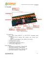
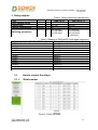
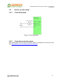
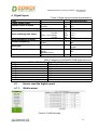
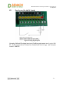
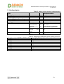
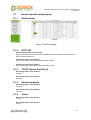
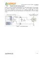
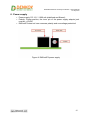
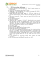
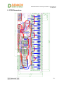
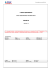
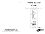
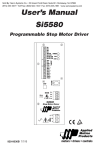
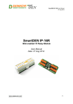
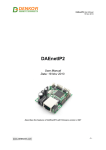
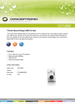
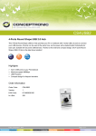
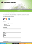
DAEnetIP3 Ethernet 12 Relay I/O Module - User's Manual
27 Sep 2013
DAEnetIP3 Ethernet 12 Relay I/O
Module
User's Manual
Date: 19 July 2014
-1-
DAEnetIP3 Ethernet 12 Relay I/O Module - User's Manual
27 Sep 2013
Content
1.
2.
3.
4.
5.
6.
7.
8.
About this document.........................................................................................3
Overview..........................................................................................................4
Relay outputs....................................................................................................5
Digital Inputs....................................................................................................9
Analog Inputs.................................................................................................12
Power supply..................................................................................................15
Installation instructions..................................................................................16
PCB Dimensions............................................................................................19
-2-
DAEnetIP3 Ethernet 12 Relay I/O Module - User's Manual
27 Sep 2013
1. About this document
This document describes the device DAEnetIP3 Ethernet TCP/IP Data Acquisition
I/O Module respectively DAEnetIP3 Wi-Fi 802.11 b/g Data Acquisition I/O Module .
This consist of DAEnetIP3-Ex or DAEnetIP3-Wx controller but the extension I/O relay
board is the main object of this document. For full description of the all features, you
can refer to DAEnetIP3 user's manual.
-3-
DAEnetIP3 Ethernet 12 Relay I/O Module - User's Manual
27 Sep 2013
2. Overview
Figure 1. Module overview
The module has:
• 12 x SPDT relays RAS-12-15 or JQC-3FC/T73 (selectable during
purchase):
o JQC-3FC/T73 (7A / 250VAC, 10A / 125VAC, 12A / 120VAC, 10A /
28VDC)
o RAS-12-15 (10A / 250VAC, 15A / 120VAC, 15A / 24VDC)
• 8 x digital inputs (0-12VDC)
• 8 x analog inputs (0-10VDC)
• Leds for: relays, digital inputs, power on
• 12VDC sensor supply output
MPN reference:
• DAE-PB-RO12-JQC/DI8/AI8 + DAEnetIP3-EB
• DAE-PB-RO12/DI8/AI8 + DAEnetIP3-EB
• DAE-PB-RO12-JQC/DI8/AI8 + DAEnetIP3-WB
• DAE-PB-RO12/DI8/AI8 + DAEnetIP3-WB
-4-
DAEnetIP3 Ethernet 12 Relay I/O Module - User's Manual
27 Sep 2013
3. Relay outputs
Type
Relay outputs count
Contact type
Current consumption
Switching parameters
Table 1. Relays electrical characteristics
RAS-12-15
JQC-3FC/T73
12 VDC
mA
A
A
A
A
12
NO, NC
30
15 (24 VDC)
15 (120 VAC)
10 (250 VAC)
12
NO, NC
30
10 (28 VDC)
12 (120 VAC)
10 (125 VAC)
7 (250 VAC)
Table 2. Mapping to DAEnetIP3 PortA digital output port
Digital output pin # (DAEnetIP3 PortA)
Relay # (from peripheral board)
PortA.0
Relay 1
PortA.1
Relay 2
PortA.2
Relay 3
PortA.3
Relay 4
PortA.4
Relay 5
PortA.5
Relay 6
PortA.6
Relay 7
PortA.7
Relay 8
PortA.8
Relay 9
PortA.9
Relay 10
PortA.10
Relay 11
PortA.11
Relay 12
3.1.
How to control the relays
3.1.1.
Web browser
Figure 2. PortA web page
-5-
DAEnetIP3 Ethernet 12 Relay I/O Module - User's Manual
27 Sep 2013
3.1.2.
HTTP API
Get all relays states
http://your.ip.address/command.html?P=admin&ASG=?&
Set all relays ON at a time
http://your.ip.address/command.html?P=admin&ASG=FFFF&
Get Relay 1 State
http://your.ip.address/command.html?P=admin&AS0=?&
Get Relay 9 State
http://your.ip.address/command.html?P=admin&AS8=?&
Set Relay 2 OFF
http://your.ip.address/command.html?P=admin&AS1=0&
Set Relay 12 OFF
http://your.ip.address/command.html?P=admin&ASB=0&
3.1.3.
TCP/IP (Virtual Serial Port)
Get all relays states
00ASG=?;
Set all relays ON at a time
00ASG=FFFF;
Get Relay 1 State
00AS0=?;
Get Relay 9 State
00AS8=?;
Set Relay 2 OFF
00AS1=0;
Set Relay 12 OFF
00ASB=0;
3.1.4.
Serial commands
Get all relays states
00ASG=?;
Set all relays ON at a time
00ASG=FFFF;
Get Relay 1 State
00AS0=?;
Get Relay 9 State
00AS8=?;
-6-
DAEnetIP3 Ethernet 12 Relay I/O Module - User's Manual
27 Sep 2013
Set Relay 2 OFF
00AS1=0;
Set Relay 12 OFF
00ASB=0;
3.1.5.
Telnet
Get all relays states
ASG=?;
Set all relays ON at a time
ASG=FFFF;
Get Relay 1 State
AS0=?;
Get Relay 9 State
AS8=?;
Set Relay 2 OFF
AS1=0;
Set Relay 12 OFF
ASB=0;
-7-
DAEnetIP3 Ethernet 12 Relay I/O Module - User's Manual
27 Sep 2013
3.2.
How to use the relays
3.2.1.
Controlling lamp
Figure 3. Controlling lamp
3.2.2.
Controlling inductive loads
More information how to control inductive loads it is possible to be found on this
link: http://denkovi.com/controlling-inductive-devices
-8-
DAEnetIP3 Ethernet 12 Relay I/O Module - User's Manual
27 Sep 2013
4. Digital Inputs
Table 3. Digital inputs electrical characteristics
Peripheral board
Type
Digital inputs count
Voltage
Current
Nominal value of inputs
Max non desctructive voltage
Input switching limit values
From 0 to 1 Voltage
Current
From 1 to 0 Voltage
Current
Input impedance at state 1
Sensor compability
2-wire
3-wire
Input type
Between supply and
inputs
Between inputs
Against reverse polarity
Isolation
Protection
VDC
mA
VDC
VDC
mA
VDC
mA
kΩ
8
12
5.2
24.0
>7.6
>3.2
<4.5
<1.8
2.2
Yes PNP
No
Resistive with Schmitt
trigger
No
No
Yes
Table 4. Mapping to DAEnetIP3 PortB digital input port
Digital input pin # (DAEnetIP3 PortB) Digital Input # (peripheral board)
PortB.0
Din1
PortB.1
Din2
PortB.2
Din3
PortB.3
Din4
PortB.4
Din5
PortB.5
Din6
PortB.6
Din7
PortB.7
Din8
4.1.
How to read the digital inputs
4.1.1.
Web browser
Figure 4. PortB web page
-9-
DAEnetIP3 Ethernet 12 Relay I/O Module - User's Manual
27 Sep 2013
4.1.2.
HTTP API
Get all digital inputs levels at a time
http://your.ip.address/command.html?P=admin&BVG=?&
Get digital input 1 level (PortB.0)
http://your.ip.address/command.html?P=admin&BV0=?&
Get analog input 8 level (PortB.7)
http://your.ip.address/command.html?P=admin&BV7=?&
4.1.3.
TCP/IP (Virtual Serial Port)
Get digital input 1 level (PortC.0)
00BV0=?;
Get digital input 8 level (PortC.7)
00BV7=?;
4.1.4.
Serial commands
Get digital input 1 level (PortC.0)
00BV0=?;
Get digital input 8 level (PortC.7)
00BV7=?;
4.1.5.
Telnet
Get digital input 1 level (PortC.0)
BV0=?;
Get digital input 8 level (PortC.7)
BV7=?;
-10-
DAEnetIP3 Ethernet 12 Relay I/O Module - User's Manual
27 Sep 2013
4.2.
How to use the digital inputs
Figure 5.Using digital inputs
Generally DAEnetIP3's digital input port (PortB) accepts levels from 0 up to 3.3V
DC. On the current device, this port is extended with Schmitt trigger and it accepts
levels 0 - 12V DC.
-11-
DAEnetIP3 Ethernet 12 Relay I/O Module - User's Manual
27 Sep 2013
5. Analog Inputs
Type
Analog inputs count
Input range
Input impedance
Max non desctructive voltage
Value of LSB
Input type
Conversion
Isoation
Protection
Table 5. Analog inputs electrical characteristics
Peripheral board
VDC
KΩ
V
mV
Resolution
Conversion time
Precision
Repeat accuracy
Beteen
analog
channel
and
supply
Against reverse
polarity
V
Sec
V
mA
8
0...10
330
24
10
Common mode
10 bits at maximum voltage
0.8...79.2
determinated by parameter
determinated by parameter
No
Yes
Table 6. Mapping to DAEnetIP3 PortC analog input port
Analg input pin # (DAEnetIP3 PortC)
Analog Input # (peripheral board)
PortC.0
Ain1
PortC.1
Ain2
PortC.2
Ain3
PortC.3
Ain4
PortC.4
Ain5
PortC.5
Ain6
PortC.6
Ain7
PortC.7
Ain8
-12-
DAEnetIP3 Ethernet 12 Relay I/O Module - User's Manual
27 Sep 2013
5.1.
How to read the analog inputs
5.1.1.
Web browser
Figure 6. PortC web page
5.1.2.
HTTP API
Get all analog inputs levels at a time
http://your.ip.address/command.html?P=admin&CV0=?&CV1=?&CV2=?&CV3=?&CV4=?
&CV5=?&CV6=?&CV7=?&
Get analog input 1 level (PortC.0)
http://your.ip.address/command.html?P=admin&CV0=?&
Get analog input 8 level (PortC.7)
http://your.ip.address/command.html?P=admin&CV7=?&
5.1.3.
TCP/IP (Virtual Serial Port)
Get analog input 1 level (PortC.0)
00CV0=?;
Get analog input 8 level (PortC.7)
00CV7=?;
5.1.4.
Serial commands
Get analog input 1 level (PortC.0)
00CV0=?;
Get analog input 8 level (PortC.7)
00CV7=?;
5.1.5.
Telnet
Get analog input 1 level (PortC.0)
CV0=?;
Get analog input 8 level (PortC.7)
CV7=?;
-13-
DAEnetIP3 Ethernet 12 Relay I/O Module - User's Manual
27 Sep 2013
5.2.
How to use the analog inputs
Bellow is shown schematic diagram how to use the analog inputs of the module
to measure temperature from LM35DZ sensor. As it is shown on the image
bellow the DAEnetIP3's analog inputs are extended to 0-10V DC via resistor
divisor (R1 and R2). So they can accept any level within this 0-10V DC voltage
range.
Figure 7. Using analog inputs
-14-
DAEnetIP3 Ethernet 12 Relay I/O Module - User's Manual
27 Sep 2013
6. Power supply
o Power supply: DC 12 V / 1000 mA (stabilized and filtered);
o Polarity: Center positive, the inner pin of the power supply adaptor jack
must be +12VDC;
o DAEnetIP3 does not have reverese polarity and overvoltage protection!
Figure 8. DAEnetIP3 power supply
-15-
DAEnetIP3 Ethernet 12 Relay I/O Module - User's Manual
27 Sep 2013
7. Installation instructions
7.1.
UTP cable connection with PC for first time
1. Connect the module RJ45 port with UTP (doesn’t matter crossover or
straight) cable.
2. Connect the PC with the other side of the UTP cable.
3. Change the IP of the PC. It may be for example 192.168.0.1. (DAEnetIP3
is shipped with 192.168.0.100)
4. Supply DAEnetIP3 with power supply 12 VDC (the middle pin of
DAEnetIP3 power jack is +12VDC). The power led (with red color) must be
on.
5. Open your browser (IE, Firefox, Opera) and type 192.168.0.100 in the
address bar.
6. Use admin for password.
7.2.
UTP cable connection with router
1. Connect DAEnetIP3 RJ45 port with UTP (doesn’t matter crossover or
straight) cable.
2. Connect PC with the other side of the UTP cable.
3. Remember or write down the IP of the PC (for example we accept it is
192.168.1.2).
4. Change the IP of the PC. It may be for example 192.168.0.1. (DAEnetIP3
is shipped with 192.168.0.100).
5. Supply DAEnetIP3 with power supply 12 VDC (the middle pin of
DAEnetIP3 power jack is +12VDC). The power led (with red color) must be
on.
6. Open your browser (IE, Firefox, Opera) and type 192.168.0.100 in the
address bar.
7. Use admin for password.
8. Open admin settings.
9. Change the Eth IP address of DAEnetIP3. Make it to be in one network
with your router and PC. For example if your router is with IP 192.168.1.1
and PC with 192.168.1.2, make DAEnetIP3 with 192.168.1.100. Eth mask
must be 255.255.255.0 and Eth gateway 192.168.1.1 (router IP)
10. Unplug the power supply.
11. Disconnect the UTP cable from PC and connect it to the router.
12. Supply again the DAEnetIP3
13. Give back the old IP of the PC (192.168.1.2)
14. Open browser and type 192.168.1.100.
15. Now you may access the DAEnetIP3 controller with router via router from
PC.
-16-
DAEnetIP3 Ethernet 12 Relay I/O Module - User's Manual
27 Sep 2013
7.3.
Wi-Fi connection with PC for first time
1. Create ad-hoc Wi-Fi network with your PC. Your OS must support this. For
example Microsoft Windows 7 supports this function. We accept the name
of Ad-Hoc (SSID) is Network, the encryption type is WEP – 64 and the
password is admin.
2. Make the IP of this wireless interface of your PC for example 192.168.1.1
and mask 255.255.255.0
3. Connect DAEnetIP3 RJ45 port with UTP (doesn’t matter crossover or
straight) cable.
4. Connect PC with the other side of the UTP cable.
5. Change the IP of LAN card of the PC. It may be for example 192.168.0.1.
(DAEnetIP3 is with 192.168.0.100).
6. Supply DAEnetIP3 with power supply 12 VDC (the middle pin of
DAEnetIP3 power jack is +12VDC). The power led (with red color) must be
on.
7. Open your browser (IE, Firefox, Opera) and type 192.168.0.100 in the
address bar.
8. Use admin for password.
9. Open Wi-Fi settings.
10. Change the Wln IP address of DAEnetIP3. Make it to be in one network
with your PC Ad-Hoc network. We accepted the IP of the PC Ad-Hoc is
192.168.1.1. So the Wln IP of the DAEnetIP3 Wi-Fi interface may be
192.168.1.2. Wln Mask = 255.255.255.0 and Wln gateway is 192.168.1.1.
11. Click “Save” button.
12. Unplug the power supply.
13. Remove the UTP cable from the PC and controller.
14. Supply again the DAEnetIP3.
15. The orange Wi-Fi status led of DAEnetIP3 must blink initially and then must
be on constantly. This means the controller is connected to the Wireless
network. If the led is off then DAEnetIP3 is not connected to the Wireless
network because some settings are not correct. If so you need to check out
the settings again.
16. If the DAEnetIP3 is connected properly, open browser and type
192.168.1.2.
17. Now you may access the DAEnetIP3 controller over Wi-Fi.
-17-
DAEnetIP3 Ethernet 12 Relay I/O Module - User's Manual
27 Sep 2013
7.4.
Wi-Fi connection with router
1. Connect DAEnetIP3 RJ45 port with UTP (doesn’t matter crossover or
straight) cable.
2. Connect PC with the other side of the UTP cable.
3. Change the IP of LAN card of the PC. It may be for example 192.168.0.1.
(DAEnetIP3 is with 192.168.0.100).
4. Supply DAEnetIP3 with power supply 12 VDC (the middle pin of
DAEnetIP3 power jack is +12VDC). The power led (with red color) must be
on.
5. Open your browser (IE, Firefox, Opera) and type 192.168.0.100 in the
address bar.
6. Use admin for password.
7. Open Wi-Fi settings.
8. Change the Wln IP address of DAEnetIP3. Make it to be in one network
with your Wi-Fi network. We accepted the IP of the Wi-Fi network is
192.168.1.X. So the Wln IP of the DAEnetIP3 Wi-Fi interface may be
192.168.1.2. Wln Mask = 255.255.255.0 and Wln gateway is 192.168.1.1
(The IP of your router). Set the SSID and WEP password.
9. Click “Save” button.
10. Unplug the power supply.
11. Remove the UTP cable from the PC and controller.
12. Supply again the DAEnetIP3 with 12VDC.
13. The orange Wi-Fi status led of DAEnetIP3 must blink initially and then
must be on constantly. This means the controller is connected to the
Wireless network. If the led is off then DAEnetIP3 is not connected to the
Wireless network because some settings are not correct. If so you need to
check out the settings again. Also you may restart your router (just in
case).
14. If the DAEnetIP3 is connected properly, open browser and type
192.168.1.2.
15. Now you may access the DAEnetIP3 controller over Wi-Fi.
-18-
DAEnetIP3 Ethernet 12 Relay I/O Module - User's Manual
27 Sep 2013
8. PCB Dimensions
-19-