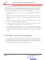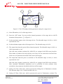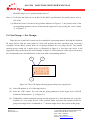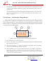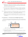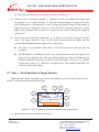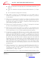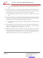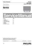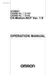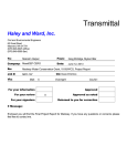
1
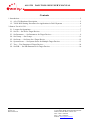
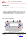
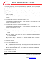
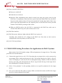
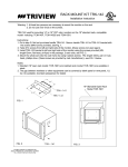
APAC Opto Electronics Inc. AO-1330 DALI TOOL BOX USER’S MANUAL V1.0 AO-1330 DALI TOOL BOX USER’S MANUAL Contents 1. Introduction....................................................................................................................................... 2 1.1. AO-1330 Hardware Description............................................................................................... 2 1.2. TOOL BOX Setting Procedures for Applications in DALI Systems .......................................4 2. Start to Use AO-1330........................................................................................................................ 7 2.1. Lessons for Operations ............................................................................................................. 7 2.2. Set ID --- Set ID for Target Devices ......................................................................................... 7 2.3. Set Parameter --- Set Parameters for Target Devices................................................................ 9 2.4. Set Group --- Set Groups ........................................................................................................ 11 2.5. Set Scene --- Set Scene for a Target Device ...........................................................................12 2.6. System Scene --- Set System Scene for Multiple Target Devices .......................................... 13 2.7. Test --- Test Functions of Target Devices ............................................................................... 14 2.8. Set PIR --- Set PIR Parameters for Target Devices ................................................................ 16 Page 1 of 2 Version 2.3 Date:2012/12/03 APAC Opto Electronics Inc. 3 Tzu Chiang Road, Hsinchu Industrial Park Hukow, Hsinchu Hsien, Taiwan 303 TEL: +886-3-5986799 FAX: +886-3-5986655 Website: www.apacoe.com.tw AO-1330 DALI TOOL BOX USER’S MANUAL 1. Introduction DALI (Digital Addressable Lighting Interface), which was originally a European standard, was ratified the international standard of lighting control for new generation, IEC-62386, by IEC in 2009. The word “DALI” referred to in this manual represents the IEC-62386 standard. In a DALI system, up to 64 (0~63) controllable devices (we call these devices target devices in this manual) can be accommodated in a loop. Therefore, every target device used in the DALI system must have a unique ID before it is installed. However, most of the DALI target devices such as electronic ballasts do not have IDs when they are manufactured. In order to resolve this problem, we have developed a helpful tool, the APACOE DALI TOOL BOX (AO-1330). By using this product, not only any DALI device can be assigned a unique ID before it is installed to the DALI system, various functions of target devices can also be set. Note that the target devices described in this manual may include LED drivers, curtain controllers, load controllers or other specific components. 1.1. AO-1330 Hardware Description 11 10 8 9 5 13 3 1 4 2 12 6 7 Figure 1.1: AO-1330 hardware description The functions of the patterns indicated/pointed by the circled numbers shown in Figure 1.1 Page 2 of 3 Version 2.3 Date:2012/12/03 APAC Opto Electronics Inc. 3 Tzu Chiang Road, Hsinchu Industrial Park Hukow, Hsinchu Hsien, Taiwan 303 TEL: +886-3-5986799 FAX: +886-3-5986655 Website: www.apacoe.com.tw AO-1330 DALI TOOL BOX USER’S MANUAL are described below by the items with the same number. For instance, the function of the pattern pointed by ⑤ is described in item 5. Note that most of these functions will be used in the later part of this manual. (1) LCD display which shows the status and functional operations of the tool. (2) Four buttons, each can be used to control one directional movement, i.e., up, down, left, and right, of the cursor. Note that throughout this manual, these buttons should be used if movement of the cursor is required. (3) The value of the cursor will be increased by 10 or plus (+) by 1. Note that in the operation described later on, we use this button to increase the value of the position at which the cursor is located. (4) The value of the cursor will be decreased by 10 or minus (-) by 1. Note that in the operation described later on, we use this button to decrease the value of the position at which the cursor is located. (5) OK/Test Button. If the cursor is located at “=”, we can read the data in the target device by pressing this button. In most situations, we can acquire output data of the target device, such as illumination, by pressing this button. In the whole context of this manual, this is the button when the phrase “pressing OK” button is mentioned. (6) Back to the first page. (7) Write data into the target device. To avoid disastrous effects resulting from improper operation, some functions can be written into the target device only when the cursor is located at “=”. In the whole context of this manual, this is the button when “write button” is mentioned. (8) Power switch of AO-1330. (9) 6V - 12V DC power input. Page 3 of 4 Version 2.3 Date:2012/12/03 APAC Opto Electronics Inc. 3 Tzu Chiang Road, Hsinchu Industrial Park Hukow, Hsinchu Hsien, Taiwan 303 TEL: +886-3-5986799 FAX: +886-3-5986655 Website: www.apacoe.com.tw AO-1330 DALI TOOL BOX USER’S MANUAL (10) Power switch for DALI bus. Pop-up to switch off. Push-down to switch on. Based on DALI stipulations, there must be exactly one (only one) power source for the DALI bus. Consequently, if there has been a power unit in the linked DALI bus, the DALI bus power (this switch) of AO-1330 must be switched off. On the other hand, if there is no power unit in the linked DALI bus, the required power of the DALI bus can be provided form the TOOL BOX by turning on this switch. When an ADCM, such as the AO-1202, is connected to the DALI bus, make sure to switch off the DALI bus power (this switch) of AO-1330. (11) DALI bus interface. (12) DALI bus power indicator, lights when the DALI bus is powered. Normally, there should be 16V voltages in the DALI bus. Note that we don’t need to distinguish the electrical polarity for the DALI bus. (13) AO-1330 busy indicator. 1.2. TOOL BOX Setting Procedures for Applications in DALI Systems Major tasks of AO-1330 include setting of IDs and parameters for target devices. The setting procedures are described below. (1) Connect the target device to AO-1330. Note that only one target device can be processed at one moment. Then, switch on the power of AO-1330 and the target device. Select “1.Set id” in the LCD display to set the device ID. To distinguish among a number of IDs for different devices, users may write down the device ID on a tag and stick the tag on the target device after finishing the ID setting of this device. (2) Select “2.Set parameter” in the operating window to set specific parameters for the target device. (3) Use a pen to draw the floor plan on a paper. Make sure that the location and ID of the target device are clearly indicated in the figure. Page 4 of 5 Version 2.3 Date:2012/12/03 APAC Opto Electronics Inc. 3 Tzu Chiang Road, Hsinchu Industrial Park Hukow, Hsinchu Hsien, Taiwan 303 TEL: +886-3-5986799 FAX: +886-3-5986655 Website: www.apacoe.com.tw AO-1330 DALI TOOL BOX USER’S MANUAL (4) Proceed to on-site construction by referring to the ID information in Step 1. Install all target devices at appropriate locations based on the floor plan. Then, link the DALI power line. Note that the connector for DALI bus must be reserved for the connection of AO-1330. (5) Set up a table, called the group table, and list all target devices in this table, as shown below. Each entry in this table indicates the group to which the target device belongs. The system can support 16 groups, numbered from 0 to 15. Group 0 1 2 3 4 5 6 7 8 9 10 11 12 13 14 15 ID ID0 Y Y ID1 Y Y ID2 Y Y Y … Y IDn Y Y (6) Connect AO-1330 to the DALI bus. Select “3.Set groups” in the LCD display of AO-1330. Carry out group setting of target devices by referring to the data established in Step 5. Note that every device can be assigned to any group. The purpose of group setting is to guarantee that when a lighting control command is executed, simultaneous operating activities can be performed by all devices in the same group. (7) Set up a table, called the scene table, and list all target devices in this table, as shown below. Each entry in this table indicates the value of a device when it is associated with the corresponding group. If the value is “- -“, then the device is not associated with the scene (not under control of the scene). There are 16 (numbered from 0-15) kinds of scenes accommodated in the system. After completing the scene setting, users can use the scene command to preset the illumination of lights in the same scene. This allows controlling of the illumination for each light in the same scene. Page 5 of 6 Version 2.3 Date:2012/12/03 APAC Opto Electronics Inc. 3 Tzu Chiang Road, Hsinchu Industrial Park Hukow, Hsinchu Hsien, Taiwan 303 TEL: +886-3-5986799 FAX: +886-3-5986655 Website: www.apacoe.com.tw AO-1330 DALI TOOL BOX USER’S MANUAL 0 1 2 3 4 ID0 100 100 0 -- 0 ID1 100 70 100 -- 0 ID2 100 70 30 -- 0 … -- -- IDn -- -- Scene 5 6 7 8 9 10 11 12 13 14 15 ID 0 -- 70 0 PS: The symbol “--” means that the scene command will not alter illumination of this light (8) Select “4.Set scene” in the LCD display of AO-1330. Carry out scene setting of target devices by referring to the data established in Step 7. Note that there are 16 scene options for every device. (9) The system scene can be set either through “4.Set scene” or “5.System scene”. Detailed procedures to set system scene (for multiple devices) will be described later on. (10) Select “6.Test” in the LCD display of AO-1330. Users can carry out control and test for the previous settings, such as group setting and scene setting. This can validate whether the realization is consistent with the initial plan. Page 6 of 7 Version 2.3 Date:2012/12/03 APAC Opto Electronics Inc. 3 Tzu Chiang Road, Hsinchu Industrial Park Hukow, Hsinchu Hsien, Taiwan 303 TEL: +886-3-5986799 FAX: +886-3-5986655 Website: www.apacoe.com.tw AO-1330 DALI TOOL BOX USER’S MANUAL 2. Start to Use AO-1330 2.1. Lessons for Operations When AO-1330 is switched on, the LCD display will show the six options as illustrated in the following figure. Move the cursor to the objective function item by using the up, down, left, and right button shown in Figure 1.1. Then, push the “OK” button to proceed with the operation. 1.set id-------------------set ID for target devices 2.set parameter --------set parameters for target devices 3.set group -------------set groups 4.set scene -------------set scenes for a target device 5.system scene ------- set system scenes for multiple target devices 6.test --------------------test functions of target devices 2.2. Set ID --- Set ID for Target Devices All DALI devices must have unique and different IDs before they are installed in the system. To perform ID setting for a target device, please connect the device directly to the DALI bus of AO-1330. At this time, make sure that no other devices are connected to this DALI bus. Otherwise, this ID number will be assigned to all connected devices. This will violate the DALI specification, which states that all devices in a loop of the DALI bus must have unique and different IDs, as mentioned above. Supply power source to the target device. Referring to Figure 2.1 and carrying out the following steps, we can proceed with the ID setting of target devices. Note that the items described in the specific number of the step are related to the objects indicated by the corresponding circled number in Figure 2.1. For instance, the DALI bus power source described in Step 2 is the object indicated by ② in Figure 2.1. This association also applies to the description in the later context. (1) Use two wires to link the DALI bus connector of AO-1330 and the target device. (2) Supply the DALI bus power by pressing the switch. Page 7 of 8 Version 2.3 Date:2012/12/03 APAC Opto Electronics Inc. 3 Tzu Chiang Road, Hsinchu Industrial Park Hukow, Hsinchu Hsien, Taiwan 303 TEL: +886-3-5986799 FAX: +886-3-5986655 Website: www.apacoe.com.tw AO-1330 DALI TOOL BOX USER’S MANUAL (3) Switch on the power source of AO-1330. (4) The DALI bus power indicator will light. (5) Move the cursor in ⑤ of Figure 2.1 to the item “1.Set ID”, and press the “OK” button ⑤ in Figure 1.1. Then, you will be in the window to set ID for the target device. AC Power Target device Such as DDL-32-40CB 1 2 3 4 5 Figure 2.1: Procedures of ID setting for a target device 2 1 Set all ballaster to 3 ID= 00 Program: Go Erase Test: On Off 99% 4 5 Figure 2.2: The LCD display showing ID setting for a target device The window that shows ID setting for a target device will display messages as shown in Figure 2.2. Move the cursor to the appropriate object arrowed by the circled number in Figure 2.2 Page 8 of 9 Version 2.3 Date:2012/12/03 APAC Opto Electronics Inc. 3 Tzu Chiang Road, Hsinchu Industrial Park Hukow, Hsinchu Hsien, Taiwan 303 TEL: +886-3-5986799 FAX: +886-3-5986655 Website: www.apacoe.com.tw AO-1330 DALI TOOL BOX USER’S MANUAL by using the buttons indicated by ② in Figure 1.1. The functions of the objects arrowed by the circled numbers are described in the following. Note that as mentioned previously, the function of the object arrowed by the circled number is related to the description of the item with the same number, e.g., statements described in item 1 are related to objects indicated by ① in the figure. (1) Select an ID number (0~63). You can use the ③ and ④ buttons in Figure 1.1 to change the value of ID. (2) Press the “OK” button to search the existent DALI devices in the loop. Starting from 0, the search will terminate if any device is found. Note that only one ID can be shown in the LED display. (3) Press the “write” button ⑦ in Figure 1.1. Then, the IDs of all target devices in the DALI bus will be set to the value shown in ① of Figure 2.2. (4) If you want to erase the ID of any target device, just press the “write” button ⑦ in Figure 1.1. This operation is irrelevant to the value ① shown in Figure 2.2. (5) For the target device with ID indicated in ①, you can emit command to switch on, switch off, or adjust the illumination of the target device by moving the cursor to the appropriate position. The range of illumination adjustment is 0-99% or “mx”, in which “mx” corresponds to 100%. 2.3. Set Parameter --- Set Parameters for Target Devices Every target device has some internal parameters that can be set. When in this stage, the LCD display will appear as shown in Figure 2.3. Move the cursor to the appropriate object arrowed by the circled number in Figure 2.3. The functions of the objects arrowed by the circled numbers are described below in the items with corresponding numbers. Page 9 of 10 Version 2.3 Date:2012/12/03 APAC Opto Electronics Inc. 3 Tzu Chiang Road, Hsinchu Industrial Park Hukow, Hsinchu Hsien, Taiwan 303 TEL: +886-3-5986799 FAX: +886-3-5986655 Website: www.apacoe.com.tw AO-1330 DALI TOOL BOX USER’S MANUAL 2 1 3 5 ID=01 Set level Max: mx Min: 20 Fail: 99 Pon: 80 F-Time: 3 F-Rate: 3 7 4 6 8 Figure 2.3: The LCD display showing parameter setting for a target device (1) Select ID number (0~63) of the target device. (2) Press the “OK” button. You can read the internal parameters of the target device with ID determined from position ① in Figure 2.3. (3) Set the maximum output value of the target device. The allowable range is 0-99%, or 100% represented as “mx”. (4) Set the minimum output value of the target device. The allowable range is 0-99%. (5) The output data when the system fails to function properly. The allowable range is 0-99%, or 100% represented as “mx”. Note that some products produced by APACOE are equipped with PIR sensor interface. These kinds of products can work properly even if they are not connected to the DALI bus. In this case, the parameters described in this item will not apply. (6) The output data when the power is switched on. The allowable range is 0-99%, or 100% represented as “mx”. Note that some products produced by APACOE are equipped with PIR sensor interface. Since automatic illumination adjustment can be performed for these products when switched-on, the parameters described in this item will not apply. (7) Setting of F-Time (Fade time), which represents the fading time of illumination variation. The allowable range is 0-15, and the default value is 0. (8) Setting of F-Rate (Fade rate), which represents the speed of illumination variation. The Page 10 of 11 Version 2.3 Date:2012/12/03 APAC Opto Electronics Inc. 3 Tzu Chiang Road, Hsinchu Industrial Park Hukow, Hsinchu Hsien, Taiwan 303 TEL: +886-3-5986799 FAX: +886-3-5986655 Website: www.apacoe.com.tw AO-1330 DALI TOOL BOX USER’S MANUAL allowable range is 0-15, and the default value is 7. Note: (i) Fade time and Fade rate are defined in the DALI specifications. For details, please refer to IEC-6386. (ii) When the cursor is located at any position indicated in Figure 2.3, the present value of the corresponding parameter can be written into the target device by pressing the “write” button ⑦ in Figure 1.1. 2.4. Set Group --- Set Groups Target devices in the DALI system can be controlled in a grouping manner. By using this function, all target devices with the same group in a loop will perform the same operation upon receiving a command. For the DALI system, there are 16 groups available for every target device. The window showing group setting for a target device is illustrated in Figure 2.4. Just move the cursor to the appropriate object arrowed by the circled number in Figure 2.4. The functions of the objects arrowed by the circled numbers are described below in the items with corresponding numbers. 2 1 ID= 01 in Groups 0 1 2 3 4 5 6 7 8 - 10 11 12 13 14 15 3 Figure 2.4: The LCD display showing group setting for a target device (1) Select ID number (0~63) of the target device. (2) Press the “OK” button. You can read the group parameters of the target device with ID determined from position ① in Figure 2.4. (3) Establish the relation among the groups and the target devices. Note that there are 16 groups available for every target device. If the position which represents the relation between a group and a target device is indicated as “-”, then the target device does not lie in this group. Page 11 of 12 Version 2.3 Date:2012/12/03 APAC Opto Electronics Inc. 3 Tzu Chiang Road, Hsinchu Industrial Park Hukow, Hsinchu Hsien, Taiwan 303 TEL: +886-3-5986799 FAX: +886-3-5986655 Website: www.apacoe.com.tw AO-1330 DALI TOOL BOX USER’S MANUAL The data shown in Figure 2.4 describes the case that target device with ID number 01 will execute the group command emitted by 14 groups, with group number from 0-8 and 0-15, except group 9. Note that when the cursor is located at any position indicated in Figure 2.4, the present value of the corresponding parameter can be written into the target device by pressing the “write” button ⑦ in Figure 1.1. 2.5. Set Scene --- Set Scene for a Target Device Every target device in the DALI system can be set for a specific scene. For the DALI system, there are 16 scenes (0~15) available for every target device. The window showing scene setting for a target device is illustrated in Figure 2.5. Just move the cursor to the appropriate object arrowed by the circled number in Figure 2.5. The functions of the objects arrowed by the circled numbers are described below in the items with corresponding numbers. 2 5 1 ID=01 set scene 10 20 30 40 60 70 80 90 -- -- -- -- 3 00 50 mx 99 4 6 Figure 2.5: The LCD display showing scene setting for a target device (1) Select ID number (0~63) of the target device. (2) Press the “OK” button. You can read the illumination of the target device with ID determined from position ① in Figure 2.5. (3) The location arrowed by ③ in Figure 2.5 represents scene 0, whose value ”00” indicates that present illumination of the target device is 0 (off). (4) The five numbers (10, 20, 30, 40, 50) in the row arrowed by ④ in Figure 2.5 represent five scenes. They are scene 1~5 starting from the left position to the right. Thus, the figure shows that the illuminations set for the scenes are: 10% for scene 1, 20% for scene 2, 30% for scene 3, 40% for scene 4, and 50% for scene 5. Page 12 of 13 Version 2.3 Date:2012/12/03 APAC Opto Electronics Inc. 3 Tzu Chiang Road, Hsinchu Industrial Park Hukow, Hsinchu Hsien, Taiwan 303 TEL: +886-3-5986799 FAX: +886-3-5986655 Website: www.apacoe.com.tw AO-1330 DALI TOOL BOX USER’S MANUAL (5) Similarly, the five numbers in the row arrowed by ⑤ in Figure 2.5 represent five scenes. They are scene 6~10 starting from the left position to the right. Thus, the figure shows that the illuminations set for the scenes are: 60% for scene 6, 70% for scene 7, 80% for scene 8, 90% for scene 9, and “mx” (100%) for scene 10. (6) In the same way, the five numbers in the row arrowed by ⑥ in Figure 2.5 represent five scenes. They are scene 11~15 starting from the left position to the right. The figure shows that the target device does not belong to scene 11~14, and the illumination for scene 15 is 99%. Note: (i) All values of scenes arrowed by ③④⑤⑥ shown in Figure 2.5 can be set by users. The allowable range is 0-99%, “mx” or “--”. When the setting is completed, users can test the illumination of the scene at which the cursor is located by pressing “OK” button. (ii) When the cursor is located at any position indicated in Figure 2.5, the present value of the corresponding parameter can be written into the target device by pressing the “write” button ⑦ in Figure 1.1. 2.6. System Scene --- Set System Scene for Multiple Target Devices The function of system scene provides another method to change or set the scene. For this function, only one scene can be established for each setting. Please refer to Figure 2.6 and follow the steps described below. 2 1 3 4 S= | 01 02 03 04 05 06 00 | mx 90 -- -- 50 -P0 | 07 12 00 ?? ?? ?? | -- -- -- -- -- -- Figure 2.6: The window showing system scene setting for multiple target devices (1) Select the number of the current scene for editing. (2) Pressing the “OK” button, users can read values of the scenes for all target devices connected in the DALU loop of AO-1330. Note that to avoid disastrous effects resulting from improper operation, present settings can Page 13 of 14 Version 2.3 Date:2012/12/03 APAC Opto Electronics Inc. 3 Tzu Chiang Road, Hsinchu Industrial Park Hukow, Hsinchu Hsien, Taiwan 303 TEL: +886-3-5986799 FAX: +886-3-5986655 Website: www.apacoe.com.tw AO-1330 DALI TOOL BOX USER’S MANUAL be written into the target device only when the cursor is located at “=”. (3) When the cursor is located at position ③ in Figure 2.6, users can change the viewing page by using the (+) or (-) button in Figure 1.1. Since the maximum number of target devices that can be displayed in a viewing page is 12, the viewing page must be changed if the number of target devices to be considered is greater 12. The AO-1330 is designed so that five viewing pages can be changed. That is, values of 60 target devices can be edited in the setting of system scene. (4) Each of the red-colored block indicated by ④ in Figure 2.6 represents setting of an target device. The upper and lower value of each block represents the ID number and the corresponding illumination of the target device, respectively. The value “??” means that no ID number is set for the target device. Thus, the data can be ignored. The ID numbers are arranged in such a way: starting from the left to the right for the upper row, then from the left to the right for the second row, and so on. If ID setting is performed manually, make sure to locate the ID with number “00” at the “01” position of upper left corner in ①. Otherwise, all target devices with numbers behind ID “00” won’t be written in the system. 2.7. Test --- Test Functions of Target Devices When the DALI system is installed, users can use this function to test the system. Please refer to Figure 2.7 and follow the steps described below. 1 2 4 8 3 7 Test: Single ID=01 Action:On Off 99% ? Scene : 12 PIR=Off Self Master 5 6 Figure 2.7: The LCD display showing test functions for target devices (1) There are three options available for selection. Page 14 of 15 Version 2.3 Date:2012/12/03 APAC Opto Electronics Inc. 3 Tzu Chiang Road, Hsinchu Industrial Park Hukow, Hsinchu Hsien, Taiwan 303 TEL: +886-3-5986799 FAX: +886-3-5986655 Website: www.apacoe.com.tw AO-1330 DALI TOOL BOX USER’S MANUAL Single: Give instructions to the single target device with ID number indicated by ② in Figure 2.7. Group: Give instructions to the group with group number indicated by ② in Figure 2.7.。 All: Give instructions to all target devices in the loop. (2) When “Single” is selected in ①, the operating range of ② is 0-63; When “Group” is selected in ①, the operating range of ② is 0-15; When “All” is selected in ①, the value of ② can be ignored. (3) When the cursor is located at the “On” position of ③ in Figure 2.7, instruction to switch on the target device will be emitted by pressing the “OK” button. Similarly, when the cursor is located at the “Off” position of ③ in Figure 2.7, instruction to switch off the target device will be emitted by pressing the “OK” button. (4) When the cursor is located at the position of ④ in Figure 2.7, the target device will output the value of selected illumination by pressing the “OK” button. (5) When the cursor is located at the position of ⑤ in Figure 2.7, scene instructions can be given to the target devices by pressing the “OK” button. The allowable range for scene is 0-15. The values shown in ① and ② will be considered for the scene instruction. (6) If a target device is equipped with a PIR sensor, users can enable or disable automatic control function of the PIR through the position ⑥ in Figure 2.7. A target device can work in the following there modes when PIR sensor is equipped. (i) The PIR disable mode in which the PIR is inactive. This mode can be achieved by moving cursor to the off position and pressing the “OK” button. (ii) The PIR self mode in which the target device will control the illumination by itself. In this mode, however, any DALI dimming command received can change to PIR disable mode. (iii) The PIR master mode in which illumination of the same group of DALI device will be enhanced when PIR sensor is active. Note that this working mode will not change when a DALI dimming command is received. This is different from the PIR self mode. (7) When the cursor stay on ⑦ at “=” sign, users can obtain PIR working mode for ID ② by pressing the “OK” button. After the PIR working mode is selected, the cursor will jump to corresponding location “Off”, “Self” or “Master”. Note that this function is only workable when the position ① “Single” is selected. (8) When the cursor stays on ⑧ at “?” sign, users can obtain the actual level shown in ④ by Page 15 of 16 Version 2.3 Date:2012/12/03 APAC Opto Electronics Inc. 3 Tzu Chiang Road, Hsinchu Industrial Park Hukow, Hsinchu Hsien, Taiwan 303 TEL: +886-3-5986799 FAX: +886-3-5986655 Website: www.apacoe.com.tw AO-1330 DALI TOOL BOX USER’S MANUAL pressing the “OK” button. However, it is noted that if the ID selected in ① is “Group” or “All”, incorrect value will result if there are multiple target devices in a DALI loop. 2.8. Set PIR --- Set PIR Parameters for Target Devices When the PIR sensor is equipped, user can define PIR parameter for power-on state. Please refer to Figure 2.8 and follow the steps described below. 2 3 4 1 5 ID=00 Lv : 0 1 Mode: Max:mx mx MG#: 00 Min:10 0 PIR up:00s dn:01min 6 7 8 Figure 2.8: The LCD display showing PIR parameters of target devices (1) Select ID number (0~63) of the target device. (2) Press the “OK” button. You can read the PIR power-on parameter of the target device with ID determined from position ① in Figure 2.8. (3) The location arrowed by ③ in Figure 2.8 represents the PIR working mode at power on. Mode “-” represents the PIR disable mode. Mode “S” represents the PIR Self mode. Mode “M”represents the PIR Master mode. (4) The location arrowed by ④ in Figure 2.8 represents the Master Mode Group Number, which means that when PIR sensor is active, illumination of all DALI devices in group ④ will be enhanced. This setting affects only when ③ is defined as “M” (Master) mode. “00”~“15” indicates the group number. To setup corresponding group, please refer to group setting in section 2.4. “ALL” indicates that illumination of all DALI devices will be enhanced when PIR sensor is active. Page 16 of 17 Version 2.3 Date:2012/12/03 APAC Opto Electronics Inc. 3 Tzu Chiang Road, Hsinchu Industrial Park Hukow, Hsinchu Hsien, Taiwan 303 TEL: +886-3-5986799 FAX: +886-3-5986655 Website: www.apacoe.com.tw AO-1330 DALI TOOL BOX USER’S MANUAL “--” indicates that illumination of no DALI device will be enhanced when PIR sensor is active. (5) The location arrowed by ⑤ in Figure 2.8 represents dimming range of the target device. By using this setting, the maximum and minimal illumination range will be can be defined. Note that, if the minimal level is not zero, the lamp can not be turned off completely. This dimming range applied at power on, when PIR ③ is defined as self or master mode. (6) The location arrowed by ⑥ in Figure 2.8 represents dimming range of target device. By using this setting, the maximum and minimal illumination range can be defined. Note that if the minimal level is not zero, the lamp can not be turned off completely. This dimming range usually is disabled. To enable this, must have DALI control host (AO-1402S). (7) When the target device operates on PIR self or master mode, human is continually not be detected, the illumination will decease gradually to the minimal level within the minutes defines in ⑦. The minimal level is select from ⑤ or ⑥ field. (8) When the target device operates on PIR self or master mode, human be detected, the illumination will be enhanced to the maximum level. The time to enable the PIR is defined in ⑧. The maximum level is selected from ⑤ or ⑥ field. For better dimming effect, try to change Fade-time parameter in Section 2.3.7. The suggested value is 2 or 3. Page 17 of 18 Version 2.3 Date:2012/12/03 APAC Opto Electronics Inc. 3 Tzu Chiang Road, Hsinchu Industrial Park Hukow, Hsinchu Hsien, Taiwan 303 TEL: +886-3-5986799 FAX: +886-3-5986655 Website: www.apacoe.com.tw