1
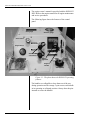
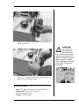
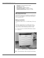
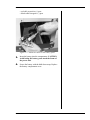
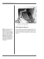
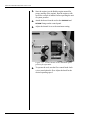
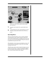
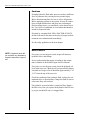
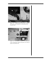
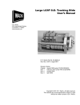
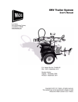
HCM-D23 Hydraulic Power Unit
User’s Manual
E.H. Wachs
600 Knightsbridge Parkway
Lincolnshire, IL 60069
www.ehwachs.com
E.H. Wachs Part No. 14-MAN-33
Revision 1, April 2015
IMPORTANT: Read this manual carefully
before starting and operating the power unit.
Copyright © 2015 E.H. Wachs. All rights reserved.
This manual may not be reproduced in whole or in part
without the written consent of E.H. Wachs.
Table of Contents
Table of Contents
Chapter 1: About the HCM-D23 Hydraulic Power Unit . . . . . . . . . . . . . . . . . . . . . . . . . . . . . 1
Features . . . . . . . . . . . . . . . . . . . . . . . . . . . . . . . . . . . . . . . . . . . . . . . . . . . . . . . . . . . . . . . . . . . . . 1
Specifications . . . . . . . . . . . . . . . . . . . . . . . . . . . . . . . . . . . . . . . . . . . . . . . . . . . . . . . . . . . . . . . . . 3
Set-Up Instructions . . . . . . . . . . . . . . . . . . . . . . . . . . . . . . . . . . . . . . . . . . . . . . . . . . . . . . . . . . . . 4
Battery Installation . . . . . . . . . . . . . . . . . . . . . . . . . . . . . . . . . . . . . . . . . . . . . . . . . . . . . . . . . . 4
Fill the Hydraulic Reservoir . . . . . . . . . . . . . . . . . . . . . . . . . . . . . . . . . . . . . . . . . . . . . . . . . . . 6
Fill the Fuel Tank . . . . . . . . . . . . . . . . . . . . . . . . . . . . . . . . . . . . . . . . . . . . . . . . . . . . . . . . . . . 7
Operating Instructions . . . . . . . . . . . . . . . . . . . . . . . . . . . . . . . . . . . . . . . . . . . . . . . . . . . . . . . . . . 9
Operating Notes . . . . . . . . . . . . . . . . . . . . . . . . . . . . . . . . . . . . . . . . . . . . . . . . . . . . . . . . . . . 11
Cautions . . . . . . . . . . . . . . . . . . . . . . . . . . . . . . . . . . . . . . . . . . . . . . . . . . . . . . . . . . . . . . . . . 12
Maintenance . . . . . . . . . . . . . . . . . . . . . . . . . . . . . . . . . . . . . . . . . . . . . . . . . . . . . . . . . . . . . . . . . 12
Chapter 2: Safety . . . . . . . . . . . . . . . . . . . . . . . . . . . . . . . . . . . . . . . . . . . . . . . . . . . . . . . . . . . . 15
Operator Safety . . . . . . . . . . . . . . . . . . . . . . . . . . . . . . . . . . . . . . . . . . . . . . . . . . . . . . . . . . . . . . 15
Safety Symbols . . . . . . . . . . . . . . . . . . . . . . . . . . . . . . . . . . . . . . . . . . . . . . . . . . . . . . . . . . . 16
Protective Equipment Requirements . . . . . . . . . . . . . . . . . . . . . . . . . . . . . . . . . . . . . . . . . . . 17
Safety Procedures . . . . . . . . . . . . . . . . . . . . . . . . . . . . . . . . . . . . . . . . . . . . . . . . . . . . . . . . . . 17
Safety Labels . . . . . . . . . . . . . . . . . . . . . . . . . . . . . . . . . . . . . . . . . . . . . . . . . . . . . . . . . . . . . . . . 19
Chapter 3: Ordering Information . . . . . . . . . . . . . . . . . . . . . . . . . . . . . . . . . . . . . . . . . . . . . . 21
Ordering Replacement Parts . . . . . . . . . . . . . . . . . . . . . . . . . . . . . . . . . . . . . . . . . . . . . . . . . . . . 21
Repair Information . . . . . . . . . . . . . . . . . . . . . . . . . . . . . . . . . . . . . . . . . . . . . . . . . . . . . . . . . . . . 21
Warranty Information . . . . . . . . . . . . . . . . . . . . . . . . . . . . . . . . . . . . . . . . . . . . . . . . . . . . . . . . . 22
Return Goods Address . . . . . . . . . . . . . . . . . . . . . . . . . . . . . . . . . . . . . . . . . . . . . . . . . . . . . . . . . 22
E.H. Wachs
Part No. 14-MAN-33, Rev. 1-0415
1
About the HCM-D23 Hydraulic Power Unit
2
Part No. 14-MAN-33, Rev. 1-0415
E.H. Wachs
Chapter 1
About the HCM-D23
Hydraulic Power Unit
The Wachs HCM-D23 hydraulic power unit provides 15
gpm hydraulic flow at a maximum pressure of 1800 psi (57
l/min at 124 bar). The unit is powered by a 23 HP diesel
engine.
The HCM-D23 is designed to operate Type 1, Type 2, or
Type 3 open-center tools.
Before operating the unit, read and understand the instructions in this manual, and in the manufacturer’s manual provided for the diesel engine.
FEATURES
The HCM-D23 hydraulic power unit includes the following
standard features:
•
•
•
•
•
•
•
•
•
Liquid cooled, 23 HP diesel engine (tier 4 compliant).
Large capacity hydraulic oil cooler.
Replaceable 10-micron hydraulic oil filter.
HTMA flat faced couplers.
Fuel level gauge and hour meter.
Auto shutdown for low engine oil pressure or high temperature.
Solid rubber tires.
Collapsible handles.
Heavy-duty single point lift ring.
E.H. Wachs
Part No. 14-MAN-33, Rev. 1-0415
1
About the HCM-D23 Hydraulic Power Unit
The engine owner’s manual is provided with the HCM-D23
HPU. Refer to the engine manual for all engine maintenance
and service procedures.
The following figure shows the features of the control
panel.
Flow gauge
Pressure gauge
Flow control
Engine hours
Hose
connections
Engine
keyswitch
Engine
throttle
Fuel tank cap
Hydraulic reservoir cap
Figure 1-1. The photo shows the HCM-D23 operating
features.
The handles are collapsible to keep them out of the way
during operation and for storage. A pin secures each handle
in its operating or collapsed position. Always have the pins
inserted to secure the handles.
2
Part No. 14-MAN-33, Rev. 1-0415
E.H. Wachs
Figure 1-2. The photo shows the pin inserted with the
handle collapsed.
CAUTION
Do not put your
hands between
the handles and
frame of the power unit when
collapsing the handles. The
handle could drop and injure
hands or fingers. A “Pinch
Point” safety label on the side
of the power unit warns of
this hazard.
Figure 1-3. The photo shows the pin inserted with the
handle in the operating position.
SPECIFICATIONS
•
•
•
Flow: 0-15 gpm @ 1800 psi (0-57 l/min @ 124 bar)
Dimensions: 39” l x 36.5” h x 28.8” w
(99 cm x 93 cm x 73 cm)
Weight: 520 lb (236 kg)
E.H. Wachs
Part No. 14-MAN-33, Rev. 1-0415
3
About the HCM-D23 Hydraulic Power Unit
•
•
•
•
•
Filtration: 10 micron return line canister
Oil Cooler: Air to oil
Fuel Capacity: 5 gallons (19 liters)
Hydraulic Oil Capacity: 4 gallons (15 liters)
Hydraulic Relief Pressure: 1800 psi (124 bar)
SET-UP INSTRUCTIONS
The HCM-D23 power unit is completely assembled before
delivery. For safe shipping, it is delivered without battery,
fuel, or hydraulic fluid.
Battery Installation
The HCM-D23 HPU uses a 12 V, 26RC battery, 540 cca @
0° F.
The battery compartment cover is held in place with 4
screws. The following figures show the battery compartment, the battery cables, and battery hold-down strap.
1. Remove the screws and take off the battery compartment cover.
Figure 1-4. Remove the battery compartment cover.
2. Connect the battery cables to the posts on the battery:
4
Part No. 14-MAN-33, Rev. 1-0415
E.H. Wachs
• red cable to positive (+) post
• black cable to negative (-) post.
Figure 1-5. Attach the cables to the battery posts.
3. Insert the battery into the compartment. CAUTION:
Avoid letting the battery posts touch the frame of
the power unit.
4. Secure the battery with the hold-down strap. Replace
the battery compartment cover.
E.H. Wachs
Part No. 14-MAN-33, Rev. 1-0415
5
About the HCM-D23 Hydraulic Power Unit
Figure 1-6. A hold-down strap is provided to secure
the battery in the compartment.
Fill the Hydraulic Reservoir
NOTE: It is extremely important that the pump is not
started until oil is in the system. Power units are shipped
without oil. Operating a pump
without oil, even for a short
time, will result in damage.
NOTE: When filling the reservoir initially, elevate the front
of the power unit slightly so
that the air can purge out of
the reservoir.
Use a premium-quality hydraulic oil (approximately 4 gallons [15 l]). The reservoir must be filled before power unit
is started. Oil should have anti-wear characteristics, excellent rust protection, and contain additives to protect against
foaming.
6
Part No. 14-MAN-33, Rev. 1-0415
E.H. Wachs
Hydraulic reservoir cap
Figure 1-7. Remove the hydraulic reservoir cap and
fill the reservoir with hydraulic oil (approximate
capacity 4 gallons [15 l]).
Wipe up any spilled oil and replace the cap tightly. Do not
operate the power unit without the cap securely in place.
Recommended oil: U.S. Oil Corporation hydraulic oil with
the following characteristics. Viscosity Index 101 Grade 32
(viscosity of 156 at 100 F; viscosity of 43.7 at 210 F).
Equivalent oils: Gulf Harmony 32A; Mobile D.T.E. 24;
Shell Tellus 32; Texaco Rando H.D. 32.
Fill the Fuel Tank
Remove the fuel cap and fill the tank with diesel fuel
(approximately 5 gallons [19 l]). The cap has a fuel level
gauge in it.
E.H. Wachs
Part No. 14-MAN-33, Rev. 1-0415
7
About the HCM-D23 Hydraulic Power Unit
Fuel tank cap
Figure 1-8. Remove the fuel tank cap and fill the tank
with diesel fuel (approximate capacity 5 gallons [19
l]).
Wipe up any spilled fuel and replace the cap tightly. Do not
operate the power unit without the cap securely in place.
NOTE: The power unit is capable of operating at 1800 psi
(124 bar). It is extremely important that the hoses used with
this unit are rated for 3000 psi (186 bar) or higher pressure.
1. Connect the pressure supply port (male coupler)
located on the right front side on the oil reservoir (item
#8 in ).
2. Connect the return hose from the remote valve or
device to the return line coupler (female coupler)
located on the left front side of the unit (item #4 in ).
3. Before starting the unit, make sure the adjustable flow
control valve (item #2 in ) is set at 0 (handle rotated
completely clockwise). Setting the valve in the "on"
position it would put enough load on the engine to prevent it from starting.
Note: Never connect or disconnect quick couplers when the
flow control valve is "on". Never connect or disconnect
quick couplers when the circuit is under pressure.
8
Part No. 14-MAN-33, Rev. 1-0415
E.H. Wachs
OPERATING INSTRUCTIONS
1. Turn the flow control knob to the OFF position (all the
way counter-clockwise).
Flow control
knob
NOTE: The adjustable flow
control valve must always be
set to 0 (completely clockwise) when there is not a
pressure hose connected to
the pressure port. When the
flow control is "on" and the
unit is allowed to "deadhead",
it will dump all the flow over
the relief valve and cause an
extreme amount of heat.
Figure 1-9. Turn the flow control all the way OFF
before starting the power unit or connecting hoses.
2. Push the throttle lever all the way down. Using the
keyswitch, jog the engine without starting it several
times to prime the pump.
Keyswitch
Figure 1-10. Turn the keyswitch briefly with the throttle at the lowest setting to jog the engine without starting it.
E.H. Wachs
Part No. 14-MAN-33, Rev. 1-0415
9
About the HCM-D23 Hydraulic Power Unit
3. Start the engine (see the Kohler engine manual for
proper starting of the engine). Run the engine at idle
speed for a couple of minutes before operating the unit
at system pressure.
4. Attach the hoses from the tool to the PRESSURE and
RETURN fittings on the control panel.
5. Adjust the throttle lever to the maximum setting.
Figure 1-11. Set the throttle to the maximum speed
position for operation.
6. To operate the tool, turn the flow control knob clockwise to start hydraulic flow. Adjust the knob for the
desired operating speed.
10
Part No. 14-MAN-33, Rev. 1-0415
E.H. Wachs
Flow control
knob
Figure 1-12. Turn the flow control in the ON direction
to operate the tool. (Control panel shown without
hoses attached.)
7. To stop the tool, turn the flow control knob back to
OFF.
8. To turn off the power unit, set the throttle lever to the
minimum speed position and then turn off the keyswitch.
Operating Notes
Make sure that the hydraulic circuit is properly plumbed
and appropriate for the available amount of oil from the
unit. A circuit with long hoses or a high-capacity tool could
lower the reservoir level considerably. The power unit must
be plumbed to an open center valve.
If the hydraulic circuit is improperly plumbed, pressure will
build immediately and dump over the relief valve setting,
causing excessive heat.
Allow the power unit to run for at least 10 minutes at a time
to make sure the battery is charged. Starting and stopping
the unit frequently, and operating for only short periods of
time, will not keep the battery fully charged.
E.H. Wachs
Part No. 14-MAN-33, Rev. 1-0415
11
About the HCM-D23 Hydraulic Power Unit
Cautions
Escaping hydraulic fluid under pressure can have sufficient
force to penetrate skin, causing serious personal injury.
Before disconnecting lines, be sure to relieve all pressure.
Before applying pressure to the system, be sure all connections are tight and that lines and hoses are not damaged.
Fluid escaping from a very small hole can be almost invisible. Use a piece of cardboard or wood rather than hands to
search for suspected leaks.
If injured by escaping fluid, SEE A DOCTOR AT ONCE.
Serious infection or reaction can develop if proper medical
treatment is not administered immediately.
See the safety guidelines in the next chapter.
MAINTENANCE
NOTE: A hydraulic hose failure could be very hazardous;
frequent inspection is important.
Every time you use the power unit, inspect all fasteners,
hydraulic hoses, and fittings.
Service and maintain the engine according to the maintenance schedule in the Kohler Engine Owner's Manual.
Every time you use the power unit, check the hydraulic oil
level in the reservoir. Check the oil level periodically during
extended use. Proper oil level should be approximately 1" to
1-1/2" from the top of the reservoir.
Check the condition of the hydraulic fluid, looking for contaminants, dirt, or discoloration. Change the fluid as soon as
it becomes dirty or discolored.
The hydraulic system includes a return line filter. Replace
the filter every time you replace the hydraulic fluid. Do not
try to get extended life out of a clogged filter.
12
Part No. 14-MAN-33, Rev. 1-0415
E.H. Wachs
Figure 1-13. A label on the side of the HPU indicates
the location of the hydraulic oil drain plug (underneath the unit).
Figure 1-14. The hydraulic oil filter is at the top of the
engine compartment. Replace the filter every time you
replace the hydraulic oil.
E.H. Wachs
Part No. 14-MAN-33, Rev. 1-0415
13
About the HCM-D23 Hydraulic Power Unit
14
Part No. 14-MAN-33, Rev. 1-0415
E.H. Wachs
Chapter 2, Safety
Chapter 2
Safety
E.H. Wachs takes great pride in designing and manufacturing safe, high-quality products. We make user safety a top
priority in the design of all our products.
In This Chapter
OPERATOR SAFETY
Read this chapter carefully before operating the hydraulic
power unit. It contains important safety instructions and
recommendations.
OPERATOR SAFETY
Follow these guidelines for safe operation of the equipment.
•
•
•
•
READ THE OPERATING MANUAL. Make sure
you understand all setup and operating instructions
before you begin.
INSPECT MACHINE AND ACCESSORIES.
Before starting the machine, look for loose bolts or
nuts, leaking lubricant, rusted components, and any
other physical conditions that may affect operation.
Properly maintaining the machine can greatly decrease
the chances for injury.
ALWAYS READ PLACARDS AND LABELS. Make
sure all placards, labels, and stickers are clearly legible
and in good condition. You can purchase replacement
labels from E.H. Wachs Company.
KEEP CLEAR OF MOVING PARTS. Keep hands,
arms, and fingers clear of all rotating or moving parts.
E.H. Wachs
Part No. 14-MAN-33, Rev. 1-0415
Look for this symbol throughout the
manual. It indicates
a personal injury
hazard.
15
About the HCM-D23 Hydraulic Power Unit
•
•
Always turn machine off before doing any adjustments
or service.
SECURE LOOSE CLOTHING AND JEWELRY.
Secure or remove loose-fitting clothing and jewelry, and
securely bind long hair, to prevent them from getting
caught in moving parts of the machine.
KEEP WORK AREA CLEAR. Keep all clutter and
nonessential materials out of the work area. Only people
directly involved with the work being performed should
have access to the area.
Safety Symbols
This icon is displayed with any safety alert that indicates a
personal injury hazard.
WARNING
This safety alert indicates a potentially hazardous situation
that, if not avoided, could result in death or serious injury.
CAUTION
This safety alert, with the personal injury hazard symbol,
indicates a potentially hazardous situation that, if not
avoided, could result in minor or moderate injury.
NOTICE
This alert indicates a situation that, if not avoided, will
result in damage to the equipment.
16
Part No. 14-MAN-33, Rev. 1-0415
E.H. Wachs
Chapter 2, Safety: Operator Safety
IMPORTANT
This alert indicates a situation that, if not avoided, may
result in damage to the equipment.
Protective Equipment Requirements
WARNING
Always wear impact resistant eye protection while operating or working near
this equipment.
For additional information on eye and face protection, refer
to Federal OSHA regulations, 29 Code of Federal Regulations, Section 1910.133., Eye and Face Protection and
American National Standards Institute, ANSI Z87.1, Occupational and Educational Eye and Face Protection. Z87.1 is
available from the American National Standards Institute,
Inc., 1430 Broadway, New York, NY 10018.
CAUTION
Personal hearing protection is recommended when operating or working near
this equipment.
Hearing protectors are required in high noise areas, 85 dBA
or greater. The operation of other tools and equipment in the
area, reflective surfaces, process noises, and resonant structures can increase the noise level in the area. For additional
information on hearing protection, refer to Federal OSHA
regulations, 29 Code of Federal Regulations, Section
1910.95, Occupational Noise Exposure and ANSI S12.6
Hearing Protectors.
Safety Procedures
All safety requirements listed below are those generally
applicable to hydraulically-powered machinery but are not
intended to be an all-inclusive list. They are intended as
guidelines only and will assist in avoiding risk of injury
when followed by qualified, experienced personnel. These
E.H. Wachs
Part No. 14-MAN-33, Rev. 1-0415
17
About the HCM-D23 Hydraulic Power Unit
precautions should be included in the comprehensive safety
program for the particular machinery, equipment, plant or
process and overseen by personnel capable of analyzing any
hazards associated with operating and maintaining the
equipment.
WARNING
Many types of
machinery have
parts that may
start moving as soon as the
hydraulic circuit is filled and
pressurized. This could result
in injury to personnel or damage to machinery.
1. Return all movable parts of the machinery being operated to their normal startup condition, if possible,
before starting unit.
2. Be sure all personnel, product, etc. are clear of
machinery before starting hydraulic unit.
3. Check to make sure any hydraulic connections which
may have been removed, replaced or disconnected
during shut down have been reconnected securely
before starting hydraulic unit.
4. Before starting the unit, perform all equipment checks
described at the beginning of the operating instructions.
5. If there are tools or machinery being operated by the
HPU that may move when hydraulic flow or pressure
are turned off or turned on, block or lock these parts in
position before shutting down the hydraulic unit.
WARNING
Make sure all personnel are clear
from the machinery being operated before
shutting down the HPU.
6. Shut down the hydraulic unit and relieve pressure
from all pressurized accumulators, actuators and lines
before removing, tearing down or performing maintenance on any remotely-located actuators, hoses, filters, valves, piping, etc.
7. Any personnel observing or working on or adjacent to
hydraulically-powered equipment must never place
themselves in a location or position that could produce
an injury in the event of:
•
•
•
•
18
a hydraulic line failure either with the unit running or
shut down;
pump or motor failure or;
pin-hole leaks in hoses or fittings;
movement of machine components during normal operation or resulting from a component malfunction or failure.
Part No. 14-MAN-33, Rev. 1-0415
E.H. Wachs
Chapter 2, Safety: Safety Labels
8. Do not inspect hoses and fittings for leaks using your
bare hands. A pin-hole leak can inject hydraulic fluid
through the skin, with the potential for serious injury.
9. Avoid locating equipment in any environment for
which it was not designed and which may create a
dangerous operating condition such as an explosive
atmosphere (e.g., gas, dust), high heat (e.g., molten
metal, furnace), chemicals, extreme moisture, etc.
WARNING
The injection of
hydraulic fluid
under the skin can
cause serious injury and
even result in death. If an
injection injury occurs, seek
medical treatment immediately.
10. Avoid bodily contact with hydraulic fluids. Some
hydraulic fluids may irritate or injure the eyes and
skin. Check with your fluid suppliers to obtain this
information.
11. Use only E.H. Wachs parts and materials when servicing the equipment. Substitute parts or materials could
produce a hazardous operating condition.
12. When piping your equipment, use only materials of
adequate size and strength to suit the flows and pressures of the system. Consider all safety factors when
selecting the strength of materials to allow for shock
and over-pressure conditions which could occur.
SAFETY LABELS
There is a safety label on each side of the unit indicating the
location of the engine fan. Keep hands away from the
engine compartment while the unit is running.
Figure 2-1. Labels on each side of the unit indicate
the location of the engine fan.
E.H. Wachs
Part No. 14-MAN-33, Rev. 1-0415
19
About the HCM-D23 Hydraulic Power Unit
A safety label warns that the engine muffler can get very
hot. Do not touch the muffler during or after operating the
power unit.
Figure 2-2. A Hot Surface label is located near the
engine muffler.
A safety label on each side of the unit warns of a pinchpoint hazard between the enclosure and the collapsible handles. Keep hands clear when lower the handles from the
operating (extended) position.
Figure 2-3. The Pinch Point label is located on both
sides of the unit by the collapsible handles.
20
Part No. 14-MAN-33, Rev. 1-0415
E.H. Wachs
Chapter 3, Ordering Information
Chapter 3
Ordering Information
In This Chapter
To place an order, request service, or get more detailed
information on any E.H. Wachs products, call us at one of
the following numbers:
ORDERING REPLACEMENT
PARTS
U.S.
800-323-8185
International: 847-537-8800
WARRANTY INFORMATION
REPAIR INFORMATION
RETURN GOODS ADDRESS
You can also visit our Web site at:
www.ehwachs.com
ORDERING REPLACEMENT PARTS
When ordering parts, refer to the drawings and parts lists in
Chapter 8. Please provide the part description and part
number for all parts you are ordering.
REPAIR INFORMATION
Please call us for an authorization number before returning
any equipment for repair or factory service. We will advise
you of shipping and handling. When you send the equipment, please include the following information:
• Your name/company name
• Your address
• Your phone number
• A description of the problem or the work to be done.
E.H. Wachs
Part No. 14-MAN-33, Rev. 1-0415
21
About the HCM-D23 Hydraulic Power Unit
Before we perform any repair, we will estimate the work
and inform you of the cost and the time to complete it.
WARRANTY INFORMATION
Enclosed with the manual is a warranty card. Please fill out
the registration card and return to E.H. Wachs. Retain the
owner’s registration record and warranty card for your
information.
RETURN GOODS ADDRESS
Return equipment for repair to the following address.
E.H. Wachs
600 Knightsbridge Parkway
Lincolnshire, Illinois 60069 USA
22
Part No. 14-MAN-33, Rev. 1-0415
E.H. Wachs