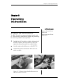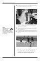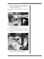
1
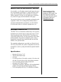
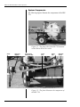
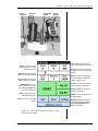
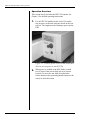
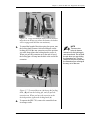
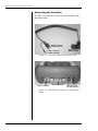
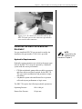
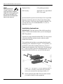
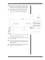
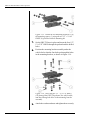
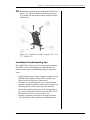
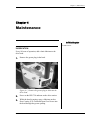
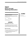
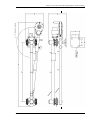
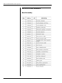
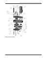
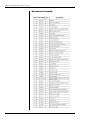
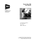
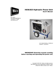
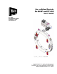
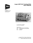
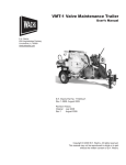
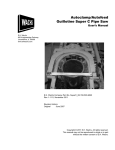
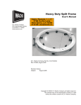
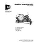
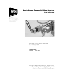
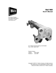
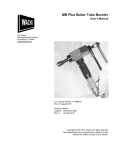
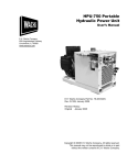
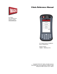
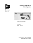
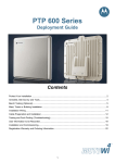
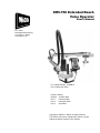
ERV-750 Extended Reach
Valve Operator
User’s Manual
E.H. Wachs
600 Knightsbridge Parkway
Lincolnshire, IL 60069
www.ehwachs.com
E.H. Wachs Part No. 79-MAN-01
Rev. 3-0409, April 2009
Revision History:
Original January 2008
Rev. 1
February 2008
Rev. 2
December 2008
Rev. 3
April 2009
Copyright © 2009 E.H. Wachs. All rights reserved.
This manual may not be reproduced in whole or in part
without the written consent of E.H. Wachs.
ERV-750 Extended Reach Valve Operator
Part No. 79-MAN-01, Rev. 3-0409
E.H. Wachs
Table of Contents
Table of Contents
Chapter 1: About the ERV-750 . . . . . . . . . . . . . . . . . . . . . . . . . . . . . . . . . . . . . . . . . . . . . . . . . 1
Purpose of This Manual . . . . . . . . . . . . . . . . . . . . . . . . . . . . . . . . . . . . . . . . . . . . . . . . . . . . . . . . . 1
How to Use The Manual . . . . . . . . . . . . . . . . . . . . . . . . . . . . . . . . . . . . . . . . . . . . . . . . . . . . . . . . 1
Symbols and Warnings . . . . . . . . . . . . . . . . . . . . . . . . . . . . . . . . . . . . . . . . . . . . . . . . . . . . . . . . . 1
Manual Updates and Revision Tracking . . . . . . . . . . . . . . . . . . . . . . . . . . . . . . . . . . . . . . . . . . . . 3
Equipment Description . . . . . . . . . . . . . . . . . . . . . . . . . . . . . . . . . . . . . . . . . . . . . . . . . . . . . . . . . 3
Specifications . . . . . . . . . . . . . . . . . . . . . . . . . . . . . . . . . . . . . . . . . . . . . . . . . . . . . . . . . . . . . . 3
System Components . . . . . . . . . . . . . . . . . . . . . . . . . . . . . . . . . . . . . . . . . . . . . . . . . . . . . . . . 4
Operation Overview . . . . . . . . . . . . . . . . . . . . . . . . . . . . . . . . . . . . . . . . . . . . . . . . . . . . . . . . . 6
Connecting the Controller . . . . . . . . . . . . . . . . . . . . . . . . . . . . . . . . . . . . . . . . . . . . . . . . . . . . 8
Installing the ERV-750 on Existing Equipment . . . . . . . . . . . . . . . . . . . . . . . . . . . . . . . . . . . . . . 9
Hydraulic Requirements . . . . . . . . . . . . . . . . . . . . . . . . . . . . . . . . . . . . . . . . . . . . . . . . . . . . . 9
Installation Instructions . . . . . . . . . . . . . . . . . . . . . . . . . . . . . . . . . . . . . . . . . . . . . . . . . . . . . 10
Installation Troubleshooting Tips . . . . . . . . . . . . . . . . . . . . . . . . . . . . . . . . . . . . . . . . . . . . . 13
Chapter 2: Safety . . . . . . . . . . . . . . . . . . . . . . . . . . . . . . . . . . . . . . . . . . . . . . . . . . . . . . . . . . . . 15
Operator Safety . . . . . . . . . . . . . . . . . . . . . . . . . . . . . . . . . . . . . . . . . . . . . . . . . . . . . . . . . . . . . . 15
Safety Symbols . . . . . . . . . . . . . . . . . . . . . . . . . . . . . . . . . . . . . . . . . . . . . . . . . . . . . . . . . . . 16
Protective Equipment Requirements . . . . . . . . . . . . . . . . . . . . . . . . . . . . . . . . . . . . . . . . . . . 17
Chapter 3: Operating Instructions . . . . . . . . . . . . . . . . . . . . . . . . . . . . . . . . . . . . . . . . . . . . . . 19
Setting Up the Valve Operator . . . . . . . . . . . . . . . . . . . . . . . . . . . . . . . . . . . . . . . . . . . . . . . . . . . 19
Performing the Valve Operation . . . . . . . . . . . . . . . . . . . . . . . . . . . . . . . . . . . . . . . . . . . . . . . . . 22
Starting the Vitals Data Logging Program . . . . . . . . . . . . . . . . . . . . . . . . . . . . . . . . . . . . . . 23
Running the Wachs Controller Program . . . . . . . . . . . . . . . . . . . . . . . . . . . . . . . . . . . . . . . . 24
Chapter 4: Maintenance . . . . . . . . . . . . . . . . . . . . . . . . . . . . . . . . . . . . . . . . . . . . . . . . . . . . . . 27
Lubrication . . . . . . . . . . . . . . . . . . . . . . . . . . . . . . . . . . . . . . . . . . . . . . . . . . . . . . . . . . . . . . . . . . 27
Chapter 5: Parts List and Ordering Information . . . . . . . . . . . . . . . . . . . . . . . . . . . . . . . . . . 29
Ordering Information . . . . . . . . . . . . . . . . . . . . . . . . . . . . . . . . . . . . . . . . . . . . . . . . . . . . . . . . . . 29
Ordering Replacement Parts . . . . . . . . . . . . . . . . . . . . . . . . . . . . . . . . . . . . . . . . . . . . . . . . . 29
Repair Information . . . . . . . . . . . . . . . . . . . . . . . . . . . . . . . . . . . . . . . . . . . . . . . . . . . . . . . . . 29
Warranty Information . . . . . . . . . . . . . . . . . . . . . . . . . . . . . . . . . . . . . . . . . . . . . . . . . . . . . . 30
Return Goods Address . . . . . . . . . . . . . . . . . . . . . . . . . . . . . . . . . . . . . . . . . . . . . . . . . . . . . . 30
Layout Drawing . . . . . . . . . . . . . . . . . . . . . . . . . . . . . . . . . . . . . . . . . . . . . . . . . . . . . . . . . . . . . . 30
E.H. Wachs
Part No. 79-MAN-01, Rev. 3-0409
i
ERV-750 Extended Reach Valve Operator
Parts Lists and Drawings . . . . . . . . . . . . . . . . . . . . . . . . . . . . . . . . . . . . . . . . . . . . . . . . . . . . . . .
Head Assembly . . . . . . . . . . . . . . . . . . . . . . . . . . . . . . . . . . . . . . . . . . . . . . . . . . . . . . . . . . .
Mechanical Assembly . . . . . . . . . . . . . . . . . . . . . . . . . . . . . . . . . . . . . . . . . . . . . . . . . . . . . .
Wiring . . . . . . . . . . . . . . . . . . . . . . . . . . . . . . . . . . . . . . . . . . . . . . . . . . . . . . . . . . . . . . . . . .
Hydraulics . . . . . . . . . . . . . . . . . . . . . . . . . . . . . . . . . . . . . . . . . . . . . . . . . . . . . . . . . . . . . . .
Installation Kit . . . . . . . . . . . . . . . . . . . . . . . . . . . . . . . . . . . . . . . . . . . . . . . . . . . . . . . . . . . .
ii
Part No. 79-MAN-01, Rev. 3-0409
32
32
34
36
37
38
E.H. Wachs
Chapter 1, About the ERV-750
Chapter 1
About the ERV-750
In This Chapter
PURPOSE OF THIS MANUAL
This manual explains how to operate and maintain the
ERV-750 extended reach valve operator. It includes instructions for set-up, operation, and maintenance. It also contains parts lists and diagrams to help you order replacement
parts and perform user-serviceable repairs.
PURPOSE OF THIS MANUAL
HOW TO USE THE MANUAL
SYMBOLS AND WARNINGS
MANUAL UPDATES AND
REVISION TRACKING
EQUIPMENT DESCRIPTION
HOW TO USE THE MANUAL
This manual is organized to help you quickly find the information you need. Each chapter describes a specific topic on
using or maintaining the equipment.
INSTALLING THE ERV-750 ON
EXISTING EQUIPMENT
Throughout this manual, refer
to this column for warnings,
cautions, and notices with
supplementary information.
Each page is designed with two columns. This large column
on the inside of the page contains instructions and illustrations. Use these instructions to operate and maintain the
equipment.
The narrower column on the outside contains additional
information such as warnings, special notes, and definitions. Refer to it for safety notes and other information.
SYMBOLS AND WARNINGS
The following symbols are used throughout this manual to
indicate special notes and warnings. They appear in the outside column of the page, next to the section they refer to.
E.H. Wachs
Part No. 79-MAN-01, Rev. 3-0409
1
ERV-750 Extended Reach Valve Operator
Make sure you understand what each symbol means, and
follow all instructions for cautions and warnings.
WARNING
A WARNING alert with the
safety alert symbol indicates
a potentially hazardous situation that could result in serious injury or death.
This is the safety alert symbol. It is used
to alert you to potential personal injury
hazards. Obey all safety messages that
follow this symbol to avoid possible
injury or death.
CAUTION
A CAUTION alert with the
safety alert symbol indicates
a potentially hazardous situation that could result in
minor or moderate injury.
CAUTION
A CAUTION alert with the
damage alert symbol indicates a situation that will
result in damage to the
equipment.
This is the equipment damage alert
symbol. It is used to alert you to potential equipment damage situations.
Obey all messages that follow this symbol to avoid damaging the equipment or
workpiece on which it is operating.
IMPORTANT
An IMPORTANT alert with
the damage alert symbol indicates a situation that may
result in damage to the
equipment.
NOTE
NOTE
A NOTE provides supplementary information or operating tips.
This symbol indicates a user note. Notes
provide additional information to supplement the instructions, or tips for easier
operation.
2
Part No. 79-MAN-01, Rev. 3-0409
E.H. Wachs
Chapter 1, About the ERV-750: Manual Updates and Revision Tracking
MANUAL UPDATES AND REVISION TRACKING
Occasionally, we will update manuals with improved operation or maintenance procedures, or with corrections if necessary. Revised manuals will be available for customers.
When a manual is revised, we will update the revision history on the title page and at the bottom of the pages.
You may have factory service or upgrades performed on the
equipment. If this service changes any technical data or
operation and maintenance procedures, we will include a
revised manual when we return the equipment to you.
Current versions of E.H.
Wachs manuals are also
available in PDF format. You
can request an electronic
copy of this manual by emailing customer service at
[email protected].
EQUIPMENT DESCRIPTION
The ERV-750 is an automated, medium-duty valve operator
mounted on an extension arm to reach valves up to 13 feet
from the pedestal mount. With the ERV-750 mounted on
your truck or utility trailer, you can reach many valves when
parked curbside. It operates on hydraulic power, using a
ruggedized, computer-based controller that can store and
transfer valve operation data.
The standard configuration is provided on a Wachs SwivelVac heavy-duty trailer; the system’s components can also be
mounted on a truck or pickup bed with the optional installation kit.
Specifications
•
•
•
•
•
•
•
•
Operates all valves 6”-60”
750 lb-ft maximum torque
0-30 rpm
13 ft arm (on Swivel Vac trailer, reaches 11 ft to the curb
side and 9 ft to the driver side) with locking extension
swivel mounting pedestal with position lock
microprocessor control system
Vitals Recon controller, a Windows CE-based handheld
pendant with operating and data logging software
4-9 ft telescoping valve key (3 ft extensions available)
E.H. Wachs
Part No. 79-MAN-01, Rev. 3-0409
3
ERV-750 Extended Reach Valve Operator
System Components
The following figures illustrate the components of the ERV750.
ERV-750
Figure 1-1. The photo shows the ERV-750 mounted
on the Wachs Swivel Vac trailer.
Head
Valve key
adapter
Telescoping
extension arm
Lower
arm
Upper
arm
Pedestal
mount
Figure 1-2. The photo illustrates the components of
the ERV-750.
4
Part No. 79-MAN-01, Rev. 3-0409
E.H. Wachs
Chapter 1, About the ERV-750: Equipment Description
Control
connector
Hydraulic
motor
Positioning
handle
Control
pendant
Figure 1-3. The photo illustrates the ERV-750 head.
Limit—Displays current torque
limit. Touch to change torque limit.
Torque—Displays current
operating torque. Touch to
change torque limit
Direction—Displays current turning direction. Touch to set turning
direction.
Highest—Displays aximum
torque during current activity
Mode—Displays current operating mode (Exercise or Manual).
Touch to change mode.
Count—Displays valve rotations during current activity.
Jog LH—Touch and hold to jog
left-hand (counter-clockwise).
START/STOP—Touch to
start or stop the valve exerciser. (Displays STOP if the
exerciser is operating.)
Jog RH—Touch and hold to jog
right-hand (clockwise).
Back—Touch to return to
Vitals Mobile program.
Settings—Touch to change valve
operating settings.
Reset—Touch to start a new
activity.
Waiting to connect—Displays
current operating status (reads
Connected to ERV-750 when
startup is complete).
Figure 1-4. The ERV-750 controller has a touchscreen for operation.
E.H. Wachs
Part No. 79-MAN-01, Rev. 3-0409
5
ERV-750 Extended Reach Valve Operator
Operation Overview
This section briefly describes the ERV-750 controls. See
Chapter 3 for detailed operating instructions.
1. For an ERV-750 installed on the Swivel Vac trailer,
turn on power to the unit using the switch on the control box. The engine must be running to power up the
ERV.
Figure 1-5. Push the power switch on the control box
down to turn on power to the ERV-750.
2. When power is enabled to the ERV, brakes in both
swivel joints of the arm lock the arm in its current
location. To move the arm, hold down the brake
release button on the positioning handle and move the
arm to its desired location.
6
Part No. 79-MAN-01, Rev. 3-0409
E.H. Wachs
Chapter 1, About the ERV-750: Equipment Description
Brake release
button
Figure 1-6. Press and hold the brake release button to
move the arm. When you release the button, the brakes
will re-engage and hold the arm stationary.
3. To extend the length of the telescoping lower arm, turn
the locking knob counter-clockwise and pull out the
locking pin. Pull the arm extension out to the position
you want, then tighten the locking knob to secure it.
When you pull the extension out to the end of travel,
the locking pin will snap into the hole at the end of the
extension.
A
B
NOTE
There are two
holes in the arm
extension for the locking pin,
one at each end. Do not hold
the pin when you are sliding
the extension out. The pin
snaps into the hole to prevent
the extension from coming all
the way out of the arm.
C
Figure 1-7. To extend the arm, (A) loosen the locking
knob, (B) pull out the locking pin, and (C) pull the
extension out. When you have the extension at the
desired position, tighten the locking knob (A).
4. To operate the ERV-750, remove the controller from
its storage cradle.
E.H. Wachs
Part No. 79-MAN-01, Rev. 3-0409
7
ERV-750 Extended Reach Valve Operator
Connecting the Controller
The ERV-750 controller is connected to the machine with a
specialized cable.
Serial connector
to ERV controller
Power connector
to ERV controller
Connector to
ERV-750 head
Figure 1-8. The photo shows the controller cable.
Power connector
Serial connector
USB connector
(for data transfer)
Figure 1-9. The ERV-750 controller connections are
shown.
8
Part No. 79-MAN-01, Rev. 3-0409
E.H. Wachs
Chapter 1, About the ERV-750: Installing the ERV-750 on Existing Equipment
Figure 1-10. To connect the controller cable to the
ERV-750 head, unscrew the connector cap and then
screw on the cable connector.
INSTALLING THE ERV-750 ON EXISTING
EQUIPMENT
You can install the ERV-750 on your truck or trailer. An
installation kit (part number 79-401-00) is provided.
Hydraulic Requirements
NOTE
A parts list for the
installation kit is
included in Chapter 5.
Hydraulic system parameters are critical to the proper operation of the ERV-750. It must be operated by a hydraulic
system with the correct performance.
•
•
PTO driven hydraulic pumps often can deliver pressures
and flows that exceed those required for the ERV-750.
This can result in malfunctions and premature component failure.
A hydraulic system with insufficient flow or pressure
will result in poor performance or logic errors.
The ERV-750 requires the following hydraulic parameters:
Operating Pressure:
1500 -1800 psi
Return Line Pressure:
110 psi max
E.H. Wachs
Part No. 79-MAN-01, Rev. 3-0409
9
ERV-750 Extended Reach Valve Operator
NOTE
Flows greater than
10 gpm require the
use of a pressure compensated flow control valve such
as Prince model #RD-100.
Excess flow must be ported
back to the reservoir.
Hydraulic Flow:
6-10 gallons per minute
Oil Viscosity:
ISO Grade 32 or equal, Mobil
DTE 24 or equal
System return line pressure must be kept as low as possible.
Excessive return line pressure will prevent release of the
ERV-750 brakes. If the return hose length for the ERV-750
exceeds four feet, it is recommended that -12 (3/4”) or
larger hose is used.
Installation Instructions
IMPORTANT: The bed or deck of the vehicle must be at
least 1/4” thick at the location where you are mounting the
ERV-750 pedestal.
At least two people should install the ERV-750. One person
will need to hold the machine in place while the other
attaches the fasteners.
The installation kit includes two mounting brackets and a
mounting spacer, illustrated in Figure 1-11. If possible, it is
preferable to attach the mounting brackets to a beam or
channel on the underside of the vehicle bed. This beam must
be 3” wide to properly space the mounting brackets. If you
mount the brackets in this way, you will omit the spacer.
Figure 1-11. The spacer (1) can be omitted if there is
a 3” beam or channel on the underside of the deck
where you can attach the mounting brackets (2).
1. Set the pedestal of the ERV-750 base at the location
you want to install it on the equipment.
10
Part No. 79-MAN-01, Rev. 3-0409
E.H. Wachs
Chapter 1, About the ERV-750: Installing the ERV-750 on Existing Equipment
2. Mark the location of the 4 holes in the ERV-750 base.
Make sure you can drill into the equipment at these
locations without causing damage to the equipment.
3. Refer to Figure 1-12 for dimensions and hole sizes.
Measure the locations for the arm latch holes and
make sure you can drill into the equipment there.
ERV-750
pedestal
Arm latch
Figure 1-12. The drawing shows the top-view layout
for mounting the ERV-750 on a vehicle.
4. Remove the ERV-750 and drill the four hole locations
using a 5/8” drill.
5. Measure the locations for the two holes for the arm
latch, as shown in Figure 1-12. Drill the two holes
using a 3/8” drill.
6. Assemble the two mounting brackets and the mounting spacer as shown in Figure 1-13.
E.H. Wachs
Part No. 79-MAN-01, Rev. 3-0409
11
ERV-750 Extended Reach Valve Operator
Figure 1-13. Attach the two mounting brackets (2) to
the mounting spacer (1) using the two 1/2”-13 x 4.5”
HHCS (9) provided with the mounting kit.
7. Set the ERV-750 base in place and insert the four 1/2”13 x 2.25” HHCS through the pedestal and the drilled
holes.
8. Position the mounting bracket assembly under the
vehicle bed so that the four bolts go through the holes
in the mounting brackets, as shown in Figure 1-14.
Figure 1-14. Insert the four 1/2”-13 x 2.25 HHCS
(10) through the ERV-750 pedestal, the vehicle deck,
and then through the holes in the mounting bracket
assembly.
9. Attach the washers and nuts and tighten them securely.
12
Part No. 79-MAN-01, Rev. 3-0409
E.H. Wachs
Chapter 1, About the ERV-750: Installing the ERV-750 on Existing Equipment
10. Install the arm latch at the location illustrated above in
Figure 1-12. Insert the fasteners as shown in Figure 115, with the nuts and washers on the underside of the
vehicle deck.
Figure 1-15. Install the arm latch using two 3/8”-16 x
1.75” HHCS (12).
Installation Troubleshooting Tips
Every ERV-750 is factory tested to verify proper operation.
If the ERV-750 is not functioning as expected after you
install it, follow these troubleshooting steps to isolate the
cause.
•
•
•
Supply hydraulic power from a separate, properly sized
hydraulic unit (ideally, a Wachs TM7 or similar connected to the auxiliary hose connections).
Reconnect to system hydraulic power. If malfunction
continues, diagnose hydraulic system failure. Install calibrated gauges to verify system pressures and flow.
Return line pressures must not exceed 25 psig. If necessary, route a dedicated return line from the ERV-750 to
the hydraulic reservoir, or increase hose size.
Routing a temporary return line to an empty oil drum
will verify brake release with low return line pressure.
E.H. Wachs
Part No. 79-MAN-01, Rev. 3-0409
13
ERV-750 Extended Reach Valve Operator
14
Part No. 79-MAN-01, Rev. 3-0409
E.H. Wachs
Chapter 2, Safety
Chapter 2
Safety
E.H. Wachs takes great pride in designing and manufacturing safe, high-quality products. We make user safety a top
priority in the design of all our products.
In This Chapter
OPERATOR SAFETY
Read this chapter carefully before operating the ERV-750.
It contains important safety instructions and recommendations.
OPERATOR SAFETY
Follow these guidelines for safe operation of the equipment.
•
•
•
•
READ THE OPERATING MANUAL. Make sure
you understand all setup and operating instructions
before you begin.
INSPECT MACHINE AND ACCESSORIES.
Before starting the machine, look for loose bolts or
nuts, leaking lubricant, rusted components, and any
other physical conditions that may affect operation.
Properly maintaining the machine can greatly decrease
the chances for injury.
ALWAYS READ PLACARDS AND LABELS. Make
sure all placards, labels, and stickers are clearly legible
and in good condition. You can purchase replacement
labels from E.H. Wachs Company.
KEEP CLEAR OF MOVING PARTS. Keep hands,
arms, and fingers clear of all rotating or moving parts.
E.H. Wachs
79-MAN-01
Look for this symbol throughout the
manual. It indicates
a personal injury
hazard.
15
ERV-750 Extended Reach Valve Operator
•
•
Always turn machine off before doing any adjustments
or service.
SECURE LOOSE CLOTHING AND JEWELRY.
Secure or remove loose-fitting clothing and jewelry, and
securely bind long hair, to prevent them from getting
caught in moving parts of the machine.
KEEP WORK AREA CLEAR. Keep all clutter and
nonessential materials out of the work area. Only people
directly involved with the work being performed should
have access to the area.
Safety Symbols
This icon is displayed with any safety alert that indicates a
personal injury hazard.
WARNING
This safety alert indicates a potentially hazardous situation
that, if not avoided, could result in death or serious injury.
CAUTION
This safety alert, with the personal injury hazard symbol,
indicates a potentially hazardous situation that, if not
avoided, could result in minor or moderate injury.
NOTICE
This alert indicates a situation that, if not avoided, will
result in damage to the equipment.
16
79-MAN-01
E.H. Wachs
Safety: Operator Safety
IMPORTANT
This alert indicates a situation that, if not avoided, may
result in damage to the equipment.
Protective Equipment Requirements
WARNING
Always wear impact resistant eye protection while operating or working near
this equipment.
For additional information on eye and face protection, refer
to Federal OSHA regulations, 29 Code of Federal Regulations, Section 1910.133., Eye and Face Protection and
American National Standards Institute, ANSI Z87.1, Occupational and Educational Eye and Face Protection. Z87.1 is
available from the American National Standards Institute,
Inc., 1430 Broadway, New York, NY 10018.
CAUTION
Personal hearing protection is recommended when operating or working near
this tool.
Hearing protectors are required in high noise areas, 85 dBA
or greater. The operation of other tools and equipment in the
area, reflective surfaces, process noises, and resonant structures can increase the noise level in the area. For additional
information on hearing protection, refer to Federal OSHA
regulations, 29 Code of Federal Regulations, Section
1910.95, Occupational Noise Exposure and ANSI S12.6
Hearing Protectors.
E.H. Wachs
79-MAN-01
17
ERV-750 Extended Reach Valve Operator
18
79-MAN-01
E.H. Wachs
Chapter 3, Operating Instructions
Chapter 3
Operating
Instructions
In This Chapter
SETTING UP THE VALVE OPERATOR
The ERV-750 can be use at any orientation from the vehicle. Follow all safety guidelines for parking and positioning
the vehicle to perform a valve operation.
SETTING UP THE VALVE
OPERATOR
PERFORMING THE VALVE
OPERATION
1. Park the Swivel Vac trailer or vehicle within reach of
the ERV-750 arm. (The arm reaches 11 feet to the
right side of the trailer, and 9 feet to the left side.)
2. Start the engine and enable power to the ERV-750.
3. Unfasten the latches that hold the ERV arm to the
trailer or vehicle.
Figure 3-1. Release the two latches that secure the
ERV-750 arm to the trailer.
E.H. Wachs
Part No. 79-MAN-01, Rev. 3-0409
19
ERV-750 Extended Reach Valve Operator
4. Hold the positioning handle on the ERV-750 head and
press down on the brake release button.
Figure 3-2. Hold down the brake release button to
move the ERV-750 arm.
NOTE
The head does not
have to be perfectly positioned over the
valve. The valve key attachment swivels to allow off-center operation.
5. While holding the brake release button, move the ERV
head over the valve.
6. If necessary, loosen the locking knob and pull out the
locking pin on the lower arm to pull out the arm extension.
A
B
C
Figure 3-3. To extend the arm, (A) loosen the locking
knob, (B) pull out the locking pin, and (C) pull the
extension out. When you have the extension at the
desired position, tighten the locking knob (A).
20
Part No. 79-MAN-01, Rev. 3-0409
E.H. Wachs
Chapter 3, Operating Instructions: Setting Up the Valve Operator
7. When the head is in position, release the brake release
button. If the extension arm is extended, tighten the
locking knob on the lower arm.
8. Insert the valve key adapter through the bottom of the
head.
Figure 3-4. Insert the valve key adapter up through
the bottom of the head.
9. If desired, insert the bolt through the hole in the valve
key adapter and attach the nut to secure the adapter in
the head.
Figure 3-5. Put the bolt through the top of the valve
key adapter and screw on the nut to secure it.
E.H. Wachs
Part No. 79-MAN-01, Rev. 3-0409
21
ERV-750 Extended Reach Valve Operator
10. Adjust the telescoping valve key to the length needed
NOTE
Add the extension
to the valve key if
necessary.
for the depth of the valve.
Locking pin
Pull top of key to extend length
Adjustment holes
Figure 3-6. Hold in the locking pin on the telescoping
valve key and pull the key out to the desired length.
Make sure to set the pin through one of the adjustment
holes.
11. Put the valve key down into the valve vault, and insert
the top of the key into the valve key adapter. Position
the socket end of the key on the valve nut.
PERFORMING THE VALVE OPERATION
When you perform the valve operation, you can operate the
ERV-750 only in controller mode (without logging valve
data), or you can use the Vitals data logging program to
record valve operating information.
1. Start the engine and set the throttle to operating speed.
NOTE
Make sure the controller is connected
to the ERV arm before powering up the control box.
2. Press the switch on the ERV-750 control box to the
22
Part No. 79-MAN-01, Rev. 3-0409
ON position. The power indicator will light.
E.H. Wachs
Chapter 3, Operating Instructions: Performing the Valve Operation
Power indicator
light
Figure 3-7. Push the switch on the control box to the
“ON” position.
3. Press the power button on the ERV pendant to turn it
on. The Windows Mobile screen will come up.
Figure 3-8. Press the power button to turn on the ERV
control pendant.
Starting the Vitals Data Logging Program
If you are going to record valve operation data, start the
Vitals program before running the ERV-750 control program. If you are not logging data, skip to the next section.
1. On the controller touch screen, press the Start menu
button and then press Vitals Mobile to start the program. The Vitals Mobile startup screen appears.
E.H. Wachs
Part No. 79-MAN-01, Rev. 3-0409
23
ERV-750 Extended Reach Valve Operator
Figure 3-9. From the Vitals Mobile startup screen,
you can start a new activity, list saved activities, or
review and change program settings.
2. To start a new valve exercising activity, touch the New Activity button.
3. You will be prompted to select an existing valve, or
enter a new valve. Refer to the Vitals Reference Manual for detailed instructions on using the Vitals Mobile
software.
4. Once you have selected or entered the required valve
information, refer to the next section to use the valve
exerciser controller program.
Running the Wachs Controller Program
Refer to the Vitals Reference Manual for detailed instructions on using the Vitals Mobile software.
24
Part No. 79-MAN-01, Rev. 3-0409
E.H. Wachs
Chapter 3, Operating Instructions: Performing the Valve Operation
Figure 3-10. Touch the buttons on the controller program screen to change settings and operate the valve
exerciser.
1. Set the torque limit by touching the Limit button and
then touching the up or down arrow. The arrows
change the torque limit in increments of 50.
2. If you know the direction the valve needs to be turned,
touch the Direction button until either LH (left hand) or
RH (right hand) is displayed.
NOTE
If you don’t know
the valve direction,
leave the Direction set to ?.
The valve exercising program
will attempt to determine the
freely turning direction.
3. Press the Start button. The button will turn red and
will display Stop. Press the button again if you need to
stop the valve operation.
4. The ERV-750 head will turn the valve until the torque
limit is reached.
5. When the torque limit is reached, the head will stop
and the controller will increment the limit up by 50 lbft. The head will reverse and turn until it reaches the
new limit.
6. Once the ERV finds the free direction of rotation, it
will turn the valve all the way to the end of travel. It
will stop when the torque limit is reached.
7. If you do not want the ERV-750 to exceed a certain
torque (for example, if you know the valve may be
E.H. Wachs
Part No. 79-MAN-01, Rev. 3-0409
25
ERV-750 Extended Reach Valve Operator
damaged by a high torque), touch the Mode button to
change the mode to MAN (manual). You will then have
to set the direction, and manually reverse the direction
and increase the torque limit.
8. When the valve operation is complete, you can touch
the Back button to return to the Vitals Mobile program
if you are logging data.
9. If you are not logging data, you can touch the Reset
button to clear the screen to start another valve operation.
26
Part No. 79-MAN-01, Rev. 3-0409
E.H. Wachs
Chapter 4, Maintenance
Chapter 4
Maintenance
In This Chapter
LUBRICATION
LUBRICATION
Every 10 hours of operation, add a chain lubricant to the
drive head.
1. Remove the grease plug in the head.
Figure 4-1. Remove the grease plug to lubricate the
drive head.
2. Power on the ERV-750 and turn on the drive motion.
3. While the head is turning, spray a lubricant such as
Dow Corning 1122 Chain and Open Gear Grease into
the head through the grease opening.
E.H. Wachs
Part No. 79-MAN-01, Rev. 3-0409
27
ERV-750 Extended Reach Valve Operator
4. Apply the spray lubricant for one full revolution of the
key.
5. Shut off the ERV-750 and replace the grease plug.
28
Part No. 79-MAN-01, Rev. 3-0409
E.H. Wachs
Chapter 5, Parts List and Ordering Information
Chapter 5
Parts List and
Ordering Information
In This Chapter
ORDERING INFORMATION
To place an order, request service, or get more detailed
information on any E.H. Wachs products, call us at one of
the following numbers:
ORDERING INFORMATION
LAYOUT DRAWING
PARTS LISTS AND DRAWINGS
U.S.
800-323-8185
International: 847-537-8800
Or visit our website at:
www.ehwachs.com
Ordering Replacement Parts
When ordering parts, refer to the parts lists and exploded
view drawings in this chapter. Please provide the part
description and part number for all parts you are ordering.
Always note your machine model number when ordering.
Repair Information
Please call us for an authorization number before returning
any equipment for repair or factory service. We will advise
you of shipping and handling. When you send the equipment, please include the following information:
• Your name/company name
• Your address
E.H. Wachs
Part No. 79-MAN-01, Rev. 3-0409
29
ERV-750 Extended Reach Valve Operator
•
•
Your phone number
A description of the problem or the work to be done.
Before we perform any repair, we will estimate the work
and inform you of the cost and the time required to complete it.
Warranty Information
Enclosed with the manual is a warranty card. Please fill out
the registration card and return to E.H. Wachs. Retain the
owner’s registration record and warranty card for your
information.
Return Goods Address
Return equipment for repair to the following address.
E.H. Wachs
600 Knightsbridge Parkway
Lincolnshire, Illinois 60069 USA
LAYOUT DRAWING
The following drawing illustrates the layout and dimensions
of the ERV-750 system.
30
Part No. 79-MAN-01, Rev. 3-0409
E.H. Wachs
Chapter 5, Parts List and Ordering Information: Layout Drawing
E.H. Wachs
Part No. 79-MAN-01, Rev. 3-0409
31
ERV-750 Extended Reach Valve Operator
PARTS LISTS AND DRAWINGS
Head Assembly
32
Part No. 79-MAN-01, Rev. 3-0409
E.H. Wachs
Chapter 5, Parts List and Ordering Information: Parts Lists and Drawings
Head Assembly Exploded View
E.H. Wachs
Part No. 79-MAN-01, Rev. 3-0409
33
ERV-750 Extended Reach Valve Operator
Mechanical Assembly
34
Part No. 79-MAN-01, Rev. 3-0409
E.H. Wachs
Chapter 5, Parts List and Ordering Information: Parts Lists and Drawings
Mechanical Assembly Exploded View
E.H. Wachs
Part No. 79-MAN-01, Rev. 3-0409
35
ERV-750 Extended Reach Valve Operator
Wiring
36
Part No. 79-MAN-01, Rev. 3-0409
E.H. Wachs
Chapter 5, Parts List and Ordering Information: Parts Lists and Drawings
Hydraulics
E.H. Wachs
Part No. 79-MAN-01, Rev. 3-0409
37
ERV-750 Extended Reach Valve Operator
Installation Kit
38
Part No. 79-MAN-01, Rev. 3-0409
E.H. Wachs
600 Knightsbridge Parkway • Lincolnshire, IL 60069
847-537-8800 • www.ehwachs.com