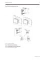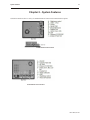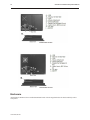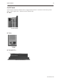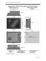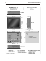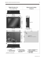
1
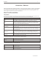
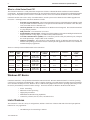
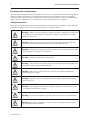
COPYRIGHT NOTICE This manual is a publication of Maple Systems, Inc., and is provided for use by its customers only. The contents of the manual are copyrighted by Maple Systems, Inc.; reproduction in whole or in part, for use other than in support of Maple Systems equipment, is prohibited without the specific written permission of Maple Systems. Gold Series is a trademark of Maple Systems, Inc. IBM, PC/AT, and PS/2 are trademarks of International Business Machines Corporation. Windows CE is a trademark of Microsoft Corporation. WebStudio is a trademark of Indusoft Corporation. All other brand and product names mentioned herein are trademarks or registered trademarks of their respective holders. WARRANTY Maple Systems warrants each product to be free from electrical and mechanical defects in materials and workmanship for a period of one year from the date of shipment. This warranty does not apply to defects in the Products caused by abuse, misuse, accident, casualty, alteration, negligence, repair not authorized by Maple Systems, use on current or voltages other than specified by Maple Systems, or application or installation not in accordance with published instruction manuals. This warranty is in lieu of any other warranty either expressed or implied. Maple Systems’ liability is limited to the repair or replacement of the Product only, and not costs of installation, removal, or damage to user’s property or other liabilities. If Maple Systems is unable to repair or replace a nonconforming Product, it may offer a refund of the amount paid to Maple Systems for such Product in full satisfaction of its warranty obligation. Maximum liability of Maple Systems is the cost of the Product. Information furnished by Maple Systems, Inc., is believed to be accurate and reliable. However, no responsibility is assumed by Maple Systems for the use of this information nor for any infringements of patents or other rights of third parties which may result from its use. No license is granted by implication, or otherwise, under any patent or patent rights of Maple Systems, Inc. Maple Systems retains the right to revise or change its products and documentation at any time without notice. IF SERVICE IS REQUIRED Package the unit in its original packaging container or, if unavailable, any suitable rigid container. If a substitute container is used, surround the unit with shock absorbing material; damage in shipment is not covered by the warranty. Include a letter with the unit describing the difficulty and designating a contact person. Send to the following address: Maple Systems, Inc., 808 134th Street SW, Suite 120, Everett, WA 98204-7333. Only Products that have been issued a Return Material Authorization (RMA) number from Maple Systems may be returned. All RMAs must be accompanied with a written purchase order for tracking purposes or, in the case of out-of-warranty repairs, for repair charges on a time and material basis. All returns will be tested to verify customer claims of noncompliance with the product warranty. Improper return packaging, which makes verification impossible, will void the warranty. Products passing the tests will be returned “AS IS” to the customer. If noncompliance is verified and is not due to customer abuse or the other exceptions described with product warranty, Maple Systems will, at its option, repair or replace the Product returned to it, freight prepaid, which fail to comply with the foregoing warranty, provided Maple Systems is notified of such noncompliance within the two-year warranty period. APPLICATIONS ASSISTANCE This manual is designed to provide the necessary information for trouble-free installation and operation of your new Panel PC; however, if you need assistance, please call Maple Systems at 425-745-3229 or visit our web site at www.maplesystems.com. Table of Contents About Your Documentation . . . . . . . . . . 1 Conventions. . . . . . . . . . . . . . . . . . . 1 What is a Gold Series Panel PC? . . . 2 Windows XP Basics . . . . . . . . . . . . . . . . . 2 List of Features. . . . . . . . . . . . . . . . . . . . 2 Chapter 1 - Installation Instructions . . . . . . . . . 5 Before You Begin . . . . . . . . . . . . . . . . . . 5 Unpacking the Unit . . . . . . . . . . . . . 5 Managing Electrostatic Discharge . . . 5 CE Compliance . . . . . . . . . . . . . . . . 5 NEMA Rating . . . . . . . . . . . . . . . . . . 5 FCC Class A Rating . . . . . . . . . . . . . 5 Environmental Considerations . . . . . 6 Safety Precautions . . . . . . . . . . . . . . 6 Control Panel Grounding . . . . . . . . . 7 Connect Panel PC Chassis Ground to Control Panel. . . . . . . . . . . . . . . . . . 7 Power Supply Selection . . . . . . . . . . 8 Cable Routing and Noise Immunity . 8 Installation. . . . . . . . . . . . . . . . . . . . . . . 9 Connect the Panel PC to Power . . . . 9 Panel Preparation . . . . . . . . . . . . . . . . . 10 Mount the Panel PC to the Panel . . . 10 Chapter 2 - System Features . . . . . . . . . . . . . . 13 Enclosure . . . . . . . . . . . . . . . . . . . . . . . . 14 On/Off Switch . . . . . . . . . . . . . . . . . 15 Microprocessor and Memory . . . . . . . . . 16 Hard Drive . . . . . . . . . . . . . . . . . . . . . . . 16 Display and Touchscreen . . . . . . . . . . . . 16 Keyboard Input . . . . . . . . . . . . . . . . . . . 16 Soft Keyboard . . . . . . . . . . . . . . . . . 16 LEDs . . . . . . . . . . . . . . . . . . . . . . . . . . . 17 Hard Drive LED . . . . . . . . . . . . . . . . 17 Power LED . . . . . . . . . . . . . . . . . . . . 17 Mouse Input. . . . . . . . . . . . . . . . . . . . . . 18 Serial Ports. . . . . . . . . . . . . . . . . . . . . . . 18 COM1 [RS232]. . . . . . . . . . . . . . . . . 18 COM2 [RS232/422/485] . . . . . . . . . 19 COM3 [RS232] & COM4 [RS232] . . . 22 Ethernet Port . . . . . . . . . . . . . . . . . . . . . 23 USB Ports . . . . . . . . . . . . . . . . . . . . . . . . 23 VGA Port . . . . . . . . . . . . . . . . . . . . . . . . 23 Parallel Printer Port . . . . . . . . . . . . . . . . 23 Compact Flash Port . . . . . . . . . . . . . . . . 23 Audio Ports . . . . . . . . . . . . . . . . . . . . . . 23 Mic In . . . . . . . . . . . . . . . . . . . . . . . 23 Line In . . . . . . . . . . . . . . . . . . . . . . . 23 Line Out . . . . . . . . . . . . . . . . . . . . . 23 Upgrade Options . . . . . . . . . . . . . . . . . . 23 Options & Upgrades for PC108A and PC110A (PC100 Series) . . . . . . . . . . 24 Options & Upgrades for PC215A and PC217A (PC200 Series) . . . . . . . . . . 24 Appendix A - Specifications . . . . . . . . . . . . . . . 25 PC108A . . . . . . . . . . . . . . . . . . . . . . . . . 25 PC110A . . . . . . . . . . . . . . . . . . . . . . . . . 27 PC215A . . . . . . . . . . . . . . . . . . . . . . . . . 29 PC217A . . . . . . . . . . . . . . . . . . . . . . . . . 31 Appendix B - Dimensional Outlines & Panel Cutouts . . . . . . . . . . . . . . . . . . . . . . . . . . . . . . 33 Appendix C - Upgrades . . . . . . . . . . . . . . . . . . 37 Microprocessor. . . . . . . . . . . . . . . . . . . . 37 PC108A/PC110A . . . . . . . . . . . . . . . 37 PC215A, PC217A. . . . . . . . . . . . . . . 37 Memory . . . . . . . . . . . . . . . . . . . . . . . . . 37 PC108A/PC110A . . . . . . . . . . . . . . . 37 PC215A/PC217A . . . . . . . . . . . . . . . 37 Hard Drive . . . . . . . . . . . . . . . . . . . . . . . 37 PC108A/PC110A . . . . . . . . . . . . . . . 37 PC215A, PC217A. . . . . . . . . . . . . . . 37 CD/DVD . . . . . . . . . . . . . . . . . . . . . . . . 37 PC108A/PC110A . . . . . . . . . . . . . . . 37 PC215A/PC217A . . . . . . . . . . . . . . . 38 Floppy Drive. . . . . . . . . . . . . . . . . . . . . . 38 PC108A/PC110A . . . . . . . . . . . . . . . 38 PC215A/PC217A . . . . . . . . . . . . . . . 38 CompactFlash Drive . . . . . . . . . . . . . . . . 38 PC108A/PC110A . . . . . . . . . . . . . . . 38 PC215A/PC217A . . . . . . . . . . . . . . . 38 Introduction 1 Introduction - Welcome Welcome to the Maple Systems' Gold Series of Panel PCs. This powerful family of touchscreen Panel PCs can be configured with any Windows XP/2000-compatible HMI software, such as Maple Systems' WebStudio, to connect to programmable logic controllers (PLCs) and motion controllers, providing the human-machine interface in industrial applications. This manual explains the installation and operation of the Gold Series. About Your Documentation Conventions In most cases, we will describe each method when the task is first discussed. The menu method is then used whenever the task is used in later procedures. Other conventions used in this book are listed in the following table. Convention Meaning Bold Characters that you must type exactly as they appear. For example, if you are directed to type a:\setup, you should type all the bold characters exactly as they are printed. Italic Placeholders for information you must provide. For example, if you are directed to type filename, you should type the actual name for a file instead of the word shown in italic type. Italics are also used to indicate a glossary term. ALL CAPITALS Directory names, file names, key names, and acronyms KEY1+KEY2 A plus sign (+) between key names means to press and hold down the first key while you press the second key. click When referring to the touch screen, click means to tap icon onscreen once with either a finger or stylus. When referring to a computer with a mouse, click refers to clicking the left mouse button once. Double-click When referring to the touchscreen, this refers to quickly tapping an onscreen icon twice in rapid succession with either a finger or a styles. When discussing a computer with a mouse, refers to quickly clicking the primary mouse button (usually the left mouse button) twice. Right-click Refers to clicking the secondary mouse button (usually the right mouse button) once. Right-clicking usually opens shortcut menus. The following terminology will be used when referring to computers and PCs: Term Meaning Panel PC Refers to the Gold Series Panel PC computer or PC Refers to a desktop PC - not the Gold Series Panel PC The following table identifies symbols and margin icons. Icon 4 4 Meaning Identifies a procedure. Indicates a reference to additional information. Indicates an important note. 1010-1020 Rev 00 2 Gold Series Installation & Operation Manual What is a Gold Series Panel PC? The Gold Series Panel PC is a fully functional computer that is built to withstand the harsh conditions found in industrial environments. Preloaded with Microsoft Windows XP, the Gold Series Panel PC can be configured for industrial automation using most XP-compatible operator interface or SCADA software, such as our industrial automation software, WebStudio. Gold Series models come with a variety of standard features, and the system can be enhanced with available upgrades and accessories. Advantages of the Gold Series Panel PCs include: • Extremely rugged components: The electrogalvanized steel chassis with aluminum bezel and fully sealed front panel allow Gold Series Panel PCs to be placed in harsh industrial environments where heat, dust, water, steam and corrosive chemicals exist. • All-in-one platform: The CPU, DRAM and even Windows XP are integrated. The Gold Series Panel PC is a plug-and-play machine. • EMI protection: The Gold Series is CE-rated. • Excellent display characteristics: Displays have high-brightness, high-contrast and high-resolution TFT displays with wide viewing angles, 16 million colors, and touchscreens. • Powerful communications capability: The Gold Series provides serial ports, Ethernet port, USB ports and audio input/output. Compact flash is also available. • Windows XP Support: The Gold Series offers platform support for Windows XP Professional. The Windows XP operating system allows the user to develop his own application software or use a number of available third-party applications. There are currently FOUR standard models in the Gold Series: Model Display Size Resolution LCD Type Brightness (cdm2) Touchscreen Ethernet Compact Flash PC108A 8.4" 800x600 16 M color SVGA TFT 220 Yes Yes Yes PC110A 10.4" 800x600 16 M color SVGA TFT 220 Yes Yes Yes PC215A 15" 1024x768 16 M color XGA TFT 350 Yes Yes Yes PC217A 17" 1280x1024 16 M color SXGA TFT 300 Yes Yes Yes Windows XP Basics Gold Series Panel PCs come preloaded with Windows XP Professional. Windows XP Professional is a real-time operating system for use in business and industrial PCs. With a complete operating system and features including support for Windows Server domains and dual processors, Windows XP is a stable and fast graphical user interface operating system that provides the security and reliability needed in business settings. Some basic benefits of Windows XP Professional include: • • • • • Secure networking Enhanced real-time processing High-speed performance Multimedia and Web browsing capabilities Connectivity with PCs, Servers, PLCs, and other devices List of Features The Gold Series comes in a variety of configurations, and has a whole host of features that make it the ideal open-platform Panel PC for every application: • One Ethernet port for networking or Internet 1010-1020 Rev 00 Introduction 3 • • • • • • • • • • • USB Ports Serial ports for RS232, RS422 or RS485 Built-in 256 MB RAM Configurations of up to 60 MB Hard Disk Space High-speed processors High-brightness, high-contrast touchscreens CompactFlash™ port Audio in/out Preloaded with Windows XP Anodized aluminum enclosures with electrogalvanized steel chassis Sealed front panels 1010-1020 Rev 00 4 Gold Series Installation & Operation Manual (This page left intentionally blank) 1010-1020 Rev 00 Installation Instructions 5 Chapter 1 - Installation Instructions Before You Begin Please read the following for proper handling of your new Panel PC. Unpacking the Unit Carefully unpack the Panel PC. Please read any instructions or cautions that appear on the shipping container. Check all material in the container against the enclosed packing list. Maple Systems, Inc. will not accept responsibility for shortages against the packing list unless notified within 30 days. The equipment and its accessories were inspected and tested by Maple Systems before shipment; all of the equipment should be in good working order. Examine the equipment carefully; if any shipping damage is evident, notify the carrier immediately. You are responsible for claim negotiations with the carrier. Save the shipping container and packing material in case the equipment needs to be stored, returned to Maple Systems, or transported for any reason. Managing Electrostatic Discharge It is best NOT to remove the rear enclosure of the Panel PC. When the rear part of the enclosure is removed, the circuitry inside is exposed to possible damage by electrostatic discharge during handling. Minimize the possibility of electrostatic discharge by: • Discharging personal static by grounding yourself prior to handling the computer • Handling the computer at a static-free grounded workstation • Connecting the frame ground ( ) connector of the computer to a clean earth ground • Placing the computer in an anti-static bag during transport CE Compliance The Gold Series Panel PCs have been tested to conform to European CE requirements per Council Directive 89/336/EEC. The European Union created these requirements to ensure conformity among products traded in those countries. Specifically, the Gold Series Panel PCs meet or exceed the noise emissions and immunity requirements as set forth in the EN50081 (Emissions) and EN50082 (Immunity) standards. These products are designed to withstand electrical noise in harsh industrial environments. They also conform to requirements that limit electrical emissions; however, this does not guarantee that the products will be totally immune from possible malfunction in cases where severe electrical noise occurs. Therefore, we strongly recommend that you follow the guidelines outlined in this chapter for proper wire routing and grounding to insure the proper operation of the Gold Series Panel PC. NEMA Rating The Gold Series Panel PCs are rated for NEMA 4 (indoor). This means that when the Panel PC is properly mounted to a panel or other enclosure, the front enclosure of the Panel PC will provide protection to the inside of the panel from splashing water, wind blown dust, or hose-directed water. The Panel PC must be installed according to the instructions in this chapter to be properly sealed. FCC Class A Rating This equipment has been tested and found to comply with the limits for a Class A digital device, pursuant to Part 15 of the FCC Rules. These limits are designed to provide reasonable protection against harmful interference when the equipment is operated in a commercial environment. This equipment generates, uses and can radiate radio frequency energy. If not installed and used in accordance with this user’s manual, it may cause harmful interference to radio communications. Operation of this equipment in a residential area is likely to cause harmful interference, in which case the user will be required to correct the interference at his own expense. 1010-1020 Rev 00 6 Gold Series Installation & Operation Manual Environmental Considerations The Gold Series is designed to operate in temperatures from 0-40° C. It is intended for indoor installations and not designed for outdoor applications. Avoid installing the Gold Series in environments with severe mechanical vibration or shocks. Do not install the computer in enclosures with rapid temperature variations or high humidity. Either will cause condensation of water inside the device and eventual damage to the computer. Safety Precautions Please observe the following precautions when installing the Gold Series Panel PCs. Failure to comply with these restrictions could result in loss of life, serious personal injury, or equipment damage. Warning: Danger of explosion if battery is incorrectly replaced. Replace only with the same or equivalent type recommended by the manufacturer. Dispose of used batteries according to manufacturer instructions. Warning: Some of the internal parts of the system may have high electrical voltage. We strongly recommend that qualified engineers open and/or disassemble the unit. Warning: Disconnect this equipment from any AC outlet before cleaning. Do not use liquid or spray detergents for cleaning. Use a damp cloth. Warning: Keep this equipment away from humidity. Warning: The openings on the enclosure are for air convection. Protect the equipment from overheating. DO NOT COVER THE OPENINGS. Warning: Make sure the voltage of the power source is correct before connecting the equipment to the power outlet. Warning: Position the power cord so that people cannot step on it. Do not place anything over the power cord. Warning: If the equipment is not used for a long time, disconnect it from the power source to avoid damage by transient over-voltage. Warning: Never pour any liquid into an opening. This could cause fire or electrical shock. Warning: Never open the equipment. For safety reasons, the equipment should be opened only by a qualified service technician. 1010-1020, Rev 00 Installation Instructions 7 Warning: If any of the following situations arise, get the equipment checked by qualified service personnel • The power cord or plug is damaged • Liquid has penetrated into the equipment. • The equipment has been exposed to moisture. • The equipment does not work well, or you cannot get it to work according to the installation reference guide. • The equipment has been dropped and damaged. • The equipment has obvious signs of breakage. DO NOT LEAVE THIS EQUIPMENT IN AN UNCONTROLLED ENVIRONMENT WHERE THE STORAGE TEMPERATURE IS BELOW - 20°C (-4° F) OR ABOVE 60°C (140° F). IT MAY DAMAGE THE EQUIPMENT. In addition, please observe all of the following safety precautions: • Read these instructions carefully. • Keep this manual for later reference. • For pluggable equipment, the power outlet must be installed near the equipment and must be easily accessible. • Put this equipment on a reliable surface during installation. Dropping it or letting it fall could cause damage. • All cautions and warnings on the equipment should be noted Control Panel Grounding The control panel should be connected to a good, high-integrity earth ground both for safety considerations and shielding purposes. Maple Systems cannot overemphasize the importance of good grounding. If you fail to use good grounding procedures during installation, sporadic malfunction of the computer may occur: · Connect the Panel PC's chassis ground terminal to a reliable earth ground with a low-resistance path. · Route all earth ground wires that lead from the Panel PC, the PLC, the power supply, and the line filter to a central earth ground point such as a barrier strip. This will ensure that no ground current from one device influences the operation of the other devices. · Connect the Panel PC chassis ground terminal to the control panel door using a heavy-gauge short braided cable or ground wire to minimize resistance. · Connect the power cable’s shield wire to the Panel PC’s chassis ground terminal. · Connect the control panel to earth ground using a copper grounding rod close to the Panel PC and control panel. Hinged doors on control panels do not provide a long-term electrical connection to the rest of the enclosure. Corrosion develops over time and prevents good electrical contract. For this reason, a separate wire braid should be installed from the hinged control panel to the rest of the enclosure. For a more in-depth overview of ground wiring techniques, refer to technical note #1027, “HMI Ground Wiring and Electrical Noise Reduction,” which you can find at http://www.maple-systems.com/cgi-bin/beimatdongon/09071027.pdf . Connect Panel PC Chassis Ground to Control Panel To reduce the possibility of electrical interference, connect the chassis ground terminal of the Panel PC to a clean earth ground. If the control panel is metal, make sure it is properly grounded. Then connect a short heavy-gauge wire (#18 AWG) from the chassis ground terminal of the computer to a mounting bolt on the control panel door. The mounting bolt must have good electrical contact to the control panel; scrape away any paint that may be covering the panel to provide a good connection. 1010-1020, Rev 00 8 Gold Series Installation & Operation Manual If the control panel is made of a non-conductive material, it is essential that you connect the chassis ground terminal of the Panel PC to a clean earth ground point located close to the panel. Power Supply Selection The power supply used to power the Panel PC has the following requirements: • • • • 100 Watt power supply Input 90~120 Vac/ 3A 60~60 Hz Output +5 VSB/1.5 A, +5 Vdc/10A, +12 Vdc/1.5A, -12 Vdc/0.22A Input current Max 3.0 A at 115 Vac The power cable for the Panel PC should be 18AWG, 2-conductor wire with a shield drain wire and protective shield (foil or braid). The shield drain wire must be connected to earth ground at both ends of the cable. Please refer to the “Connect the Panel PC to Power” section for more information. A power line filter installed at the AC input to the Panel PC power supply is highly recommended as a safeguard against conducted RF noise, which is often present on factory power lines. The wires connecting the output of the power line filter to the power supply should be kept as short as possible to minimize any additional noise pickup. The case of the power line filter should be connected to a quiet earth ground. The power line filter should have a current rating of at least 3 Amps with common mode and differential mode attenuation. Do not use the power supply used to provide power to the computer to power switching relays, solenoids, or other active devices. AC jack AC jack on back of Panel PC for power connection Cable Routing and Noise Immunity Follow these guidelines when routing cable to the Panel PC: · Always route the computer communication cable and the power cable away from any AC voltage or rapidly switching DC control lines. · Never bundle the computer cables together with 120VAC power wires or with relay wiring. · Try to keep at least 8 inches (20 cm) of separation between the Panel PC cables and other power wiring. If voltages greater than 120VAC are used in the system, greater separation is required. · If the Panel PC cables must come near AC wiring, make sure they cross at 90 degrees. · Run AC power wires in a separate grounded conduit to reduce electrical noise interference. · Keep the cable lengths for the computer as short as possible. Do not coil excess cable and place it next to AC powered equipment. · Cover any equipment used in the enclosure that operates at high frequency or high current levels with a grounded metal shield. 1010-1020, Rev 00 Installation Instructions 9 Installation It is necessary to follow all installation procedures described in this chapter for electrical noise immunity and CE compliance. Your Maple Systems Panel PC is designed to connect easily to your PLC. External rear connectors provide quick connections for power, communications and programming wiring. There are four serial port connections on the rear of the touchscreen computer. COM1, COM3 and COM4 are fixed for RS-232, while COM2 is selectable for RS-232, RS-422, RS-485. Connect the Panel PC to Power The PC110A, PC215A, and PC217A all have AC jacks for connection of an AC power adapter. AC jack To connect the PC110A connect a three pronged 100-240 VAC power adapter with 100 W output to the AC jack. To connect the PC215A and PC217A, connect a three pronged 100-240 VAC power adapter with 200 W output to the AC jack. Use the power cable to plug into the connector on the back of the unit. The PC108A has a DC power supply on the side of the unit. To connect the PC108A to power, connect a 24 VCD with 60W output to the DC jack on the side of the unit. 1010-1020, Rev 00 10 Gold Series Installation & Operation Manual Panel Preparation A metal panel or mounting surface with a minimum thickness of 15 gauge (0.059 inch/3.3mm) if cold-rolled steel or hardened steel, or 10 gauge (0.101 inch/2.6mm) if aluminum alloy (6061-T6 preferred) is required. Thinner panels or surfaces may bow between the mounting clamps and not form a seal with the gasket. The area of the panel or mounting surface where the gasket comes into contact must be flat and free of scratches, pits, and other features that prevent the gasket from sealing properly. If the panel or mounting surface is not uniform, thick, flat, stiff, or smooth enough, then a sealant such as silicone may be required. WARNING The touchscreen computer requires a stiff, flat, smooth mounting surface free of blemishes to seal properly to NEMA 4. The diagrams in Appendix C show the dimensions of the panel cutout required for proper installation of the all models. Clean and deburr the panel cutout before the touchscreen computer is installed. Mount the Panel PC to the Panel The Gold Series Panel PC can be mounted flush to the panel. 1010-1020, Rev 00 Installation Instructions 11 Panel/Wall Mounting Instructions \ Step 1: Step 2: Step 3: Step 4: Step 5: Step 6: Lock the Hook Sheet. Place the Panel PC in the hole. Put the hooks on the hook sheet. Lock the hooks by M4 screws and M4 nuts. Rotate the M4 screws to tight on the wall. Reverse the M4 nuts to tighten. 1010-1020, Rev 00 Installation Instructions 12 CAUTION: Do not over-tighten the screws beyond snugness, or you may damage the housing. REINSTALLATION: Because the gasket will take a “set” to the panel, be sure to reinstall the touchscreen computer to the same panel cutout when a NEMA 4 seal is required. For best results, also replace the gasket itself. 1010-1020, Rev 00 System Features 13 Chapter 2 - System Features Gold Series Panel PCs have a variety of standard hardware features and communications options. PC108A Hardware Features and Ports PC110A Hardware Features and Ports 1010-1020, Rev 00 14 Gold Series Installation & Operation Manual PC215A Hardware and Ports PC217A Hardware and Ports Enclosure All Gold Series Panel PCs have anodized aluminum bezels with electrogalvanized steel chassis and fully sealed front panels. 1010-1020, Rev 00 System Features 15 On/Off Switch Each Gold Series Panel PC ON/OFF switch is a toggle located on the unit. Locations for each unit are pictured below. On the toggle switch, - indicates ON and O indicates OFF. PC108A Side View of PC108A PC110A Rear View of PC110A PC215A/PC217A Bottom view of PC215A/PC217A 1010-1020, Rev 00 16 Gold Series Installation & Operation Manual Microprocessor and Memory Standard models of the Gold Series Panel PCs come with the following microprocessors. Where indicated, microprocessor can be upgraded. Model Microprocessor Upgradable To PC108A Via Eden 733 MHz processor Not available PC110A Via Eden 733 MHz processor Not available PC215A Intel® Celeron ® 2.0 GHz Up to Intel Pentium IV 2.8 GHz PC217A Intel Celeron 2.0 GHz Up to Intel Pentium IV 2.8 GHz Hard Drive All Gold Series Panel PC standard models have 40 Gig hard drives. The PC215A and PC217A can both be upgraded to either 60 Gig or 80 Gig. Display and Touchscreen All Gold Series Panel PCs come with touchscreen displays as standard equipment. Other display specifications follow: Model Type PC108A SVGA TFT LCD PC110A SVGA TFT LCD PC215A XGA TFT LCD PC217A SXGA TFT LCD Colors 16 M colors Resolution Brightness Viewing Angle (T/B/L®) 800 x 600 220 cd/m2 60°/40°/60°/60° 800 x 600 220 cd/m2 65°/65°/55°/55° 1024 x 768 350 cd/m2 40°/60°/60°/60° cd/m2 70°/60°/70°/70° 1280 x 1024 300 All displays have brightness control, which can be adjusted by means of a brightness control potentiometer on the back of the panel. Keyboard Input Two options exist for keyboard input. A keyboard can be plugged into one of the Gold Series Panel PC's keyboard/mouse ports, or USB keyboard and mouse may be plugged into a USB Port. Additionally, Windows XP Professional allows for use of a soft keyboard that can be displayed on the touchscreen display. Soft Keyboard If you choose to use the soft keyboard, there is a soft keyboard utility available through Windows XP. 4To access the soft keyboard… 1. 1010-1020, Rev 00 From Windows, select Start-All Programs-Accessories-Accessibility-On screen keyboard. System Features 17 2. The soft keyboard appears onscreen. Use either a mouse or the touchscreen to use the keyboard. LEDs Two status LEDs can be found on the bezel around front of the Gold Series Panel PCs. The PC108A Status LEDs are pictured below. On the PC215A and PC217A, Status LEDs are located on the left-hand side of the bezel. On the PC110A, the status LED is located along the bottom of the bezel. The PC110A also has an additional status LED that indicates Ethernet status. PC108A Status LEDs Hard Drive LED The hard drive LED blinks when the hard drive is in use, indicating that memory on the hard drive is being accessed. Power LED The Power LED lights when the Panel PC is powered on. 1010-1020, Rev 00 18 Gold Series Installation & Operation Manual Mouse Input Navigation on the Gold Series Panel PC can be accomplished either via the touchscreen or via attachment of a mouse. Two options are available for attaching a mouse - by either using the mouse port or attaching a USB mouse. Any Windows-compatible mouse device can be plugged into one of the Panel PC's keyboard/mouse ports, or a USB mouse can be plugged into one of the Panel PC's USB ports. Because Gold Series Panel PCs are pre-loaded with Windows XP, most mouse devices are plug and play. Serial Ports The PC215 and PC217 have four DE9 connectors for serial devices, and the PC108 and PC110 have two. COM1, COM3 & COM4 are fixed for RS-232. COM2 is selectable for RS232/422/485. The pinouts for each port are below. Restrict cable length to less than 500 feet (150m) for RS-422/RS485 devices and less than 50 feet (15m) for RS-232 devices in order to avoid communication problems. COM1 [RS232] Pinout Pin # Symbol Function 1 DCD Data Carrier Detect 2 RxD Received Data 3 TxD Transmitted Data 4 DTR Data Terminal Ready 5 GND Signal Ground 6 DSR Data Set Ready 7 RTS Ready to send output 8 CTS Clear to send 9 Not Used 1010-1020, Rev 00 System Features 19 COM2 [RS232/422/485] Pinout Pin # RS232 RS422 RS485 1 DCD Tx- Tx- 2 RxD Tx+ Tx+ 3 TxD Rx+ Rx+ 4 DTR Rx- Rx- 5 GND GND GND 6 DSR RTS- Not used 7 RTS RTS+ Not used 8 CTS CTS+ Not used 9 Not Used Not used Not used Configuring for RS232, RS422 or RS485 COM2 is configurable as RS232, RS422 or RS485 by configuring jumpers. To do this, jumper pins must be configured at JP11 for the PC215A and PC217A, or at JP3 for the PC108A and PC110A, all of which are clearly labeled on the boards of each Panel PC. Configuring Jumpers Jumpers consist of two or three metal pins with a plastic base mounted on the card. Using a jumper cap, it is possible to connect the pins. Hardware is set up by opening or closing jumper pins. Jumper Definition Representation in Diagram 2 pin jumper 3 pin jumper 1010-1020, Rev 00 20 Gold Series Installation & Operation Manual jumper block jumper cap 2 pin jumper closed (enabled) 3 pin jumper 2-3 pin closed (enabled) Jumper Block 1-2 pin closed (enabled) 1010-1020, Rev 00 System Features 21 Setting COM2 jumpers on PC108A/PC110A for RS232, RS422 or RS485 1010-1020, Rev 00 22 Gold Series Installation & Operation Manual Setting COM2 jumpers on PC215A/PC217A for RS232, RS422 or RS485 COM3 [RS232] & COM4 [RS232] Pinout Pin # Symbol Function 1 DCD Data Carrier Detect 2 Rx Receive 3 Tx Transmit 4 DTR Data Terminal Ready 5 GND Signal Ground 6 DSR Data Set Ready 7 RTS Ready to send output 8 CTS Clear to send 9 Not used 1010-1020, Rev 00 System Features 23 Ethernet Port A 10/100/1000 Mbps Ethernet port is available for connection to a network, switch or router, allowing high speed networking communications options. On the PC USB Ports All Gold Series Panel PCs have USB ports for connection of USB devices, including USB mouse, keyboard, printer, video and other devices with a USB connector. The PC108 and PC110 have two USB 1.1 host ports, and the PC215 and PC217 have two USB 2.1 host ports. VGA Port Video equipment such as a projector or additional display can be connected to the VGA ports of the PC215A and PC217A. Maximum resolution of VGA monitors is 1600 x 1200. It may be necessary to download drivers for any additional monitors - check the manufacturer's instructions for more information. Parallel Printer Port Any Windows XP-compatible printer may be attached via the parallel printer port. It may be necessary to download drivers for printers. Check your printer manufacturer's instruction. Compact Flash Port The PC108A and PC110A have built-in Type II CompactFlash™ port for use with a CompactFlash card. The PC215A and PC217A have the option of a factory-installed Type II IDE CompactFlash port. Audio Ports It is possible to record and play audio files on all Gold Series Panel PCs with the audio ports. Mic In Record Windows XP-compatible sound files by attaching a microphone to the Mic In audio port, available on all Gold Series models. Line In Audio Line In is available for attachment of compatible sound-playing devices such as CD and MP3 players. Line Out Play Windows-compatible sound files by attaching speakers to Line-Out audio ports, available on all models. Upgrade Options Upgrades are available for all models. Upgrades are listed below. 1010-1020, Rev 00 24 Gold Series Installation & Operation Manual Options & Upgrades for PC108A and PC110A (PC100 Series) Item Options Memory 256 MB (standard), 512 MB (upgrade) Hard Drive 2.5" 40 GB (standard), 2.5" 60 GB (upgrade), 2.5" 80 GB (upgrade) Power Supply PC108A 24VDC, 60W (standard), PC110A 120VAC, 100W (standard), PC110A 24VDC, 60W (upgrade) Fan/Fanless Fan (standard), Fanless (optional - not compatible with 120VAC ) Options & Upgrades for PC215A and PC217A (PC200 Series) Items Options CPU Intel Celeron 2.0 Ghz (standard), Intel Celeron 2.4 Ghz (upgrade), Intel Celeron 2.6 Ghz (upgrade), Intel Celeron 2.8 Ghz (upgrade), Intel Pentium 4 2.4 Ghz (upgrade), Intel Pentium 4 2.8 Ghz (upgrade) Memory 256 MB DDR (standard), 512 MB DDR (upgrade), 1 GB DDR (upgrade) Hard Drive 3.5" 40 GB (standard), 3.5" 80 GB (upgrade) Compact Flash IDE CompactFlash card module (option) CD/DVD Drive Slim CD-ROM (option), Slim CD RW (option), Slim DVD-R (option), Slim DVD-RW (option) Floppy Drive Slim 1.44" Floppy Drive (option) 1010-1020, Rev 00 Specifications 25 Appendix A - Specifications PC108A Mechanical Material: Aluminum front bezel and electro-galvanized steel chassis Mounting: Panel Wiring: DC input jack for power and D-style communication connectors Weight: 11 pounds [5 kg] Environmental Protection: NEMA 4 (IP65) Operating Temperature: 32 to +104º F [0 to 40º C] Storage Temperature: -4 to +140º F [-20 to 60º C] Operating Humidity: 20-90% RH (non-condensing) Electrical Noise Emissions and Immunity Emissions:EN55011 (Group 1, Class B)—Generic commercial, light & heavy industrial environments EN50081-1 Generic domestic and light industrial environments EN50081-2 Generic heavy industrial environments Immunity:EN50082-1 Generic domestic and light industrial environments EN50082-2 Generic heavy industrial environments Power Requirements Input Voltage: 24 VDC Power Requirement: 60W DC Backup Battery: 3.0 V CR2032 for Clock Display Type: SVGA TFT 800 x 600 pixels Size: 8.4 inches [213mm] diagonal Backlight: CCFL with 20,000 hour minimum lifespan Display: 16 Million color TFT, 220 cd/m², contrast controlled by potentiometer on rear Touchscreen Type: 5-wire analog resistive Light Transmission: 82% Life: 10 million keypresses Communications Serial ports: 2 Ports DE9S COM1:RS-232 1010-1020, Rev 00 26 Gold Series Installation & Operation Manual COM2 is RS-232/RS422/RS485 Baud Rates:9600, 19200, 38400, 57600, 115200 Type:Point-to-point serial communications USB Ports: 2 USB 1.1 Ethernet: 10/100/1000 BaseT Ethernet Internal Features Microprocessor: Via® Eden™ 733 MHz Memory: 256 MB SDRAM expandable to 512 MB Audio Port: Line In/Line Out/Mic Built-in real-time clock Storage Built-in Type II Compact Flash Port 1010-1020, Rev 00 Specifications 27 PC110A Mechanical Material: Anodized aluminum bezel and electro-galvanized steel chassis Mounting: Panel Wiring: AC input jack for power and D-style communication connectors Weight: 13.2 pounds [6 kg] Environmental Protection: NEMA 4 (IP65) Operating Temperature: +32 to +104º F [0 to 40º C] Storage Temperature: -4 to +140º F [-20 to 60º C] Operating Humidity: 20-90% RH (non-condensing) Electrical Noise Emissions and Immunity Emissions:EN55011 (Group 1, Class B)—Generic commercial, light & heavy industrial environments EN50081-1 Generic domestic and light industrial environments EN50081-2 Generic heavy industrial environments Immunity:EN50082-1 Generic domestic and light industrial environments EN50082-2 Generic heavy industrial environments Power Requirements Input Voltage: 100 to 120 VAC @ 60 HZ or 200 to 240 VAC @ 50 HZ Power Requirements: 100 W AC Backup Battery: 3.0 V CR2032 for clock Display Type: SVGA Color TFT LCD Size: 10.4 inches diagonal [264 mm] Backlight: CCFL x 2 with 50,000 hour minimum lifespan Display: 16 million -color TFT, 220 cd/m², contrast adjustment on rear potentiometer Touchscreen Type: 5-wire analog resistive Light Transmission: 82% Life: 10 Million Keypresses Communications Serial ports: 2 ports DE9S COM1 is RS-232 COM2 is RS-232/RS422/RS485 Baud Rates:9600, 19200, 38400, 57600, 115200 Parallel Printer:DB25S supports SPP/EPP/EPC USB Ports: 2 USB 1.1 1010-1020, Rev 00 28 Gold Series Installation & Operation Manual Ethernet: 10/100/1000 BaseT Internal Features Microprocessor: Via Eden 733 MHz Memory: 256 MB SDRAM, upgradable to 512 MB Audio Port: Line out/Line In/Mic Built-in real-time clock Expansion Compact Flash port 1010-1020, Rev 00 Specifications 29 PC215A Mechanical Material: Anodized aluminum bezel and electro-galvanized steel chassis Mounting: Panel Wiring: AC input jack for power and D-style communication connectors Weight: 20.9 pounds [9.5 kg] Environmental Protection: NEMA 4 (IP65) Operating Temperature: +32 to +104º F [0 to 40º C] Storage Temperature: -4 to +140º F [-20 to 60º C] Operating Humidity: 20-90% RH (non-condensing) Electrical Noise Emissions and Immunity Emissions:EN55011 (Group 1, Class B)—Generic commercial, light & heavy industrial environments EN50081-1 Generic domestic and light industrial environments EN50081-2 Generic heavy industrial environments Immunity:EN50082-1 Generic domestic and light industrial environments EN50082-2 Generic heavy industrial environments Power Requirements Input Voltage: 100 to 120 VAC @ 60 HZ; or 200 to 240 VAC @ 50 HZ Power Requirements: 200 W AC Backup Battery: 3.0 V CR2032 for clock Display Type: XGA Color TFT, 1024 x 768 pixels Size: 15 inches diagonal [381 mm] Backlight: CCFL x 2 with 50,000 hour minimum lifespan Display: 16 million color TFT, 350 cd/m², 400:1 contrast Touchscreen Type: 7-wire analog resistive Transmission: 82% Life: 10 million keypresses Communications Serial ports: 4 COM ports, DE9S COM1 is RS-232 COM2 is RS-232/RS422/RS485 COM3 is RS232 COM4 is RS232 Baud Rates:9600, 19200, 38400, 57600, 115200 1010-1020, Rev 00 30 Gold Series Installation & Operation Manual Type:Point-to-point serial communications USB Ports: 2 USB 2.0 (12 mbps) Ethernet: 10/100/1000 BaseT Ethernet Communications Internal Features Microprocessor: Intel Celeron 2.0 GHz, expandable to Intel Pentium 4 2.8 GHz Memory: 256 MB DDR, expandable to 1 G Audio Port: Line out/Line in/Mic Built-in real-time clock 1010-1020, Rev 00 Specifications 31 PC217A Mechanical Material: Anodized aluminum bezel with electro-galvanized steel chassis Mounting: Panel Wiring: AC input jack for power and D-style communications connectors Weight: 28.6 pounds [13 kg] Environmental Protection: NEMA 4 (IP65) Operating Temperature: +32 to +104º F [0 to 40º C] Storage Temperature: -4 to +140º F [-20 to 60º C] Operating Humidity: 20-90% RH (non-condensing) Electrical Noise Emissions and Immunity Emissions:EN55011 (Group 1, Class B)—Generic commercial, light & heavy industrial environments EN50081-1 Generic domestic and light industrial environments EN50081-2 Generic heavy industrial environments Immunity:EN50082-1 Generic domestic and light industrial environments EN50082-2 Generic heavy industrial environments Power Requirements Input Voltage: 100-120 VAC @ 60 HZ or 200 to 240 VAC @ 50 HZ Power Requirements: 200 W AC Backup Battery: 3.0 V CR2032 for clock Display Type: SXGA Color TFT LCD Size: 17 inches diagonal[432 mm] Backlight: CCFLwith 50,000 hour minimum lifespan Display: 16 million color TFT, 300 cd/m², 500:1 contrast Touchscreen Type: 7-wire analog resistive Communications Serial ports: 4 COM Ports, DE9S COM1 is RS-232 COM2 is RS-232/RS422/RS485 COM3 is RS232 COM4 is RS232 Baud Rates:9600, 19200, 38400, 57600, 115200 1010-1020, Rev 00 32 Gold Series Installation & Operation Manual Type:Point-to-point serial communications USB Ports: 2 USB 2.0 (12 mbps) Ethernet: 10/100/1000BaseT Ethernet Communications Internal Features Microprocessor: Intel Celeron 2.0 GHz, upgradable to Intel Pentium 4 2.8 GHz Memory: 256 MB DDR, Upgradable to 512 MB DDR Audio Port: Line out/Line In/Mic Built-in real-time clock 1010-1020, Rev 00 Appendix B - Dimensional Outlines & Panel Cutouts 33 Appendix B - Dimensional Outlines & Panel Cutouts 1010-1020, Rev 00 34 1010-1020, Rev 00 Gold Series Installation & Operation Manual Appendix B - Dimensional Outlines & Panel Cutouts 35 1010-1020, Rev 00 36 1010-1020, Rev 00 Gold Series Installation & Operation Manual Upgrades 37 Appendix C - Upgrades The following upgrades are available for an additional charge: Microprocessor PC108A/PC110A Not Available PC215A, PC217A Intel Celeron 2.4 Ghz Intel Celeron 2.6 Ghz Intel Celeron 2.8 Ghz Intel Pentium 4 2.4 Ghz Intel Pentium 4 2.8 Ghz Memory PC108A/PC110A 512 MB SDRAM PC215A/PC217A 512 MB DDR 1 GB DDR Hard Drive PC108A/PC110A 3.5" 60 GB 3.5" 80 GB PC215A, PC217A 3.5" 80 GB CD/DVD PC108A/PC110A Not Available 1010-1020, Rev 00 38 Gold Series Installation & Operation Manual PC215A/PC217A Slim CD-ROM drive Slim CD-RW drive Slim DVD-R drive Slim DVD-RW drive Floppy Drive PC108A/PC110A Not Available PC215A/PC217A Slim 1.44" Floppy Disk Drive CompactFlash Drive PC108A/PC110A Standard PC215A/PC217A IDE CompactFlash Card Module Other upgrades and options may be available. Contact Maple Systems for more information. 1010-1020, Rev 00 Index 39 Index A M Audio . . . . . . . . . . . . . . . . . . . . . . . 23 Memory . . . . . . . . . . . . . . . . . . . . . . 16 B Mic In . . . . . . . . . . . . . . . . . . . . . . . 23 brightness control . . . . . . . . . . . . . . . . . 16 Microprocessor . . . . . . . . . . . . . . . . . . 16 C Mount the HMI to the Panel . . . . . . . . . . . . 10 Cable Routing . . . . . . . . . . . . . . . . . . . . 8 Mouse . . . . . . . . . . . . . . . . . . . . . . . 18 Cable Routing and Noise Immunity. . . . . . . . . 8 N CE Compliance . . . . . . . . . . . . . . . . . . . 5 NEMA rating . . . . . . . . . . . . . . . . . . . . 5 COM1 . . . . . . . . . . . . . . . . . . . . . . . 18 NEMA Rating . . . . . . . . . . . . . . . . . . . . 5 COM2 . . . . . . . . . . . . . . . . . . . . . . . 19 Noise Immunity . . . . . . . . . . . . . . . . . . . 8 COM3 . . . . . . . . . . . . . . . . . . . . . . . 22 O Compact Flash . . . . . . . . . . . . . . . . . . . 23 On/Off Switch . . . . . . . . . . . . . . . . . . . 15 Control panel grounding . . . . . . . . . . . . . . 7 P D Panel Preparation . . . . . . . . . . . . . . . . . . 9 Display . . . . . . . . . . . . . . . . . . . . . . . 16 Port wiring . . . . . . . . . . . . . . . . . . . . . 9 E Power LED . . . . . . . . . . . . . . . . . . . . 17 Electrostatic Discharge, managing . . . . . . . . . 5 Power supply . . . . . . . . . . . . . . . . . . . . 8 Enclosure . . . . . . . . . . . . . . . . . . . . . 14 Power Supply . . . . . . . . . . . . . . . . . . . . 8 Ethernet . . . . . . . . . . . . . . . . . . . . . . 23 Printer . . . . . . . . . . . . . . . . . . . . . . . 23 Ethernet LED . . . . . . . . . . . . . . . . . . . 17 S F Safety Precautions. . . . . . . . . . . . . . . . . . 6 FCC Class A . . . . . . . . . . . . . . . . . . . . 5 Serial Ports . . . . . . . . . . . . . . . . . . . . . 18 FCC Class A Rating. . . . . . . . . . . . . . . . . 5 Soft keyboard . . . . . . . . . . . . . . . . . . . 16 G Specifications . . . . . . . . . . . . . . . . . . . 25 Grounding . . . . . . . . . . . . . . . . . . . . . . 7 T H Touchscreen . . . . . . . . . . . . . . . . . . . . 16 Hard drive . . . . . . . . . . . . . . . . . . . . . 16 U Hard Drive LED . . . . . . . . . . . . . . . . . . 17 Unpacking . . . . . . . . . . . . . . . . . . . . . . 5 I Upgrade . . . . . . . . . . . . . . . . . . . . . . 23 Installing the OIT . . . . . . . . . . . . . . . . . . 9 USB . . . . . . . . . . . . . . . . . . . . . . . . 23 K V Keyboard. . . . . . . . . . . . . . . . . . . . . . 16 VGA . . . . . . . . . . . . . . . . . . . . . . . . 23 L W LEDs . . . . . . . . . . . . . . . . . . . . . . . . 17 Wall mounting . . . . . . . . . . . . . . . . . . . 11 Windows XP . . . . . . . . . . . . . . . . . . . . 2 1010-1020, Rev 00