1
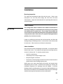
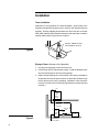
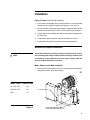
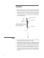
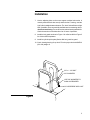
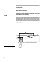
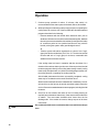
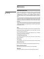
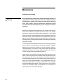
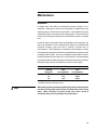
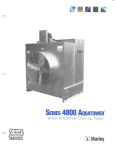
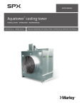
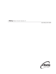
Aquatower
®
User Manual
OM-3800/4800B
Manual 92-1311G
1
Contents
Tower Installation .................................................................................... 3
Piping to Tower ....................................................................................... 4
Mechanical Equipment Installation .......................................................... 5
Motor Electrical Connections ................................................................... 8
Starting and Operating Instructions ......................................................... 9
Maintenance Instructions ...................................................................... 11
Blowdown ............................................................................................. 12
Seasonal Shutdown Instructions ........................................................... 13
Troubleshooting .................................................................................... 15
Disassembly and Reassembly .............................................................. 16
Wiring Diagrams ................................................................................... 19
Parts List ............................................................................................... 22
The following defined terms are used throughout this manual to bring attention
to the presence of hazards of various risk levels, or to important information
concerning the life of the product.
▲ Warning
Indicates presence of a hazard which can cause severe personal injury,
death or substantial property damage if ignored.
▲ Note
Indicates special instructions on installation, operation or maintenance
which are important but not related to personal injury hazards.
▲ Note
2
This Manual contains vital information for the proper installation and
operation of your cooling tower. Carefully read the manual before
installation or operation of the tower and follow all instructions. Save
this manual for future reference.
Installation
Receiving Inspection
The motor and miscellaneous parts ship with the tower. Check motor
nameplate to be sure that power supply and motor have the same
characteristics. Inspect the entire shipment for any damage that may have
occurred in transit.
Tower Location
▲ Warning
The cooling tower must be located at such distance and direction to
avoid the possibility of contaminated tower discharge air being drawn
into building fresh air intake ducts. The purchaser should obtain the
services of a Licensed Professional Engineer or Registered Architect to
certify that the location of the tower is in compliance with applicable air
pollution, fire, and clean air codes.
Locate so prevailing wind will blow into the louvered face, and direct fan
discharge away from building surfaces. Locate so there is free air flow to and
from the tower. Allow clearance on all sides for maintenance.
Indoor Installation
Use a duct from the tower air discharge to the outside. You may also want to
install an inlet air duct. Do not allow the total pressure loss through ducts to
exceed 0.10 inches H2O. To minimize pressure losses:
•
Use 20% oversize ducts.
•
Avoid sharp turns or abrupt changes in size.
•
Keep duct length to a minimum.
•
Screened or louvered openings should have a net free area at least 20%
greater than the tower discharge opening area.
Attach ducts to the tower using flexible connections, and support ducts
independently from the tower. Provide access openings for servicing the
mechanical equipment if air discharge ducts are installed. If the duct
discharges into the prevailing wind, you may need to install a windbreak or an
elbow to serve as a deflector. Ducts installed on towers with year-round usage
should be water tight and insulated to prevent condensation.
➠
3
Installation
Tower Installation
Install tower in a level position on a stable foundation. Anchor tower to the
foundation through holes at base of tower, using four 3/8” diameter bolts (not
supplied). Remove strapping and brackets from the louver face on models
4850, 4860, and 4870 and reinstall the bolts to the cold water basin. Install the
overflow (3800 models only) as shown in Figure 1.
INSTALL DRAIN FITTING
WITH GASKET ON TOP
Figure 1
Piping to Tower (Summer–Only Operation)
1. Use large enough piping to minimize friction loss.
2. Connect float valve to makeup water supply. Install the threaded valve
stem and float located in the loose parts package.
3. Install a valved blowdown line at some point in the system, preferably in
the hot water line near the top of the tower, so that water will flow through
the line whenever the pump is operating. (Blowdown is the continuous
removal of a small amount of water during operation to retard scale and
corrosion.)
Inlet
Cooling
Tower
with
Bottom
Outlet
Gravity Line
from Outlet
Make-Up
Line
Indoor
Storage
Tank
Figure 2
4
Overflow and
Drain to Sewer
Pump
Heat
Load
Installation
Piping to Tower (Year–Round Operation)
1. If your tower must operate during freezing weather, it is recommended
that the tower be installed for gravity flow operation. See Figure 2.
2. Provide an indoor open type storage tank with a capacity that will contain
all water that will drain into the tank from the system during shutdown.
3. Connect tower outlet to storage tank. Bottom outlet option should be used
for gravity flow.
4. Install makeup water, bleed-off, overflow and drain lines on tank.
5. Insulate and heat water lines exposed to freezing temperatures.
Mechanical Equipment Installation
Aquatowers with factory-installed controls ship with the motor, sheave,
belt, and belt guard factory-installed. Remove shipping stiffener plate
and hardware at the adjustable end of the motor support plate and
proceed to Motor Electrical Connections.
▲ Note
Motor, Sheave, and V-Belt Installation
1. Check the motor nameplate to be sure its voltage, phase and frequency
ratings are the same as the power supply.
➠
Motor Frame Fastener Size
56–143T–145T
5/16"
182T thru 215T
3/8"
254T
1/2"
Figure 3
1/4" TAP SCREW
SUPPORT BRACKET
(WITH ADJUSTMENT SLOTS)
5
Installation
2. Make sure the fan is tightly secured to the bearing housing shaft and that
it rotates freely. Make sure the bearing housing is secured to its support.
3. Attach motor to motor base with four bolts, flat washers, lock washers and
nuts provided, see Figure 3. You may want to loosen the adjusting bolts
and raise the motor base so you can reach under the motor base to tighten
the motor hold-down bolts.
MOTOR SHEAVE
PLUMB LINE
SHEAVES MUST BE PARALLEL TO
EACH OTHER AND IN THE SAME
PLANE OF OPERATION
FAN SHEAVE
Figure 4
4. Apply a rust preventive coating to the motor shaft to prevent shaft
corrosion and to ease sheave installation and removal.
5. Install motor sheave and align it with fan sheave. Motor support brackets
are slotted to assist in alignment. See Figure 3. A plumb line will be helpful
in aligning sheaves. See Figure 4. Model 4861 and 3861 fan sheave has
two grooves, but uses only one belt and a single-groove motor sheave.
6. Remove the fan guard and fan cylinder splice plate (Series 4800 only) at
the top of the fan cylinder. Install the belt over the fan by passing the belt
over the fan and rotating the fan blades past the belt. Install the belt onto
the sheaves.
6
Installation
7. Use the adjusting bolts on the motor support to adjust belt tension. A
correctly tensioned belt does not slip when the fan is running—and the
“tight” side is straight between sheaves. The “slack” side will have a slight
bow. If possible, use a commercially available tension measuring device.
Avoid over-tensioning. Too much tension reduces bearing and belt life.
Check the tension on new belts after 8 to 12 hours of operation.
8. Install the belt guard as shown in Figure 3 for a Series 4800 or Figure 5
for a Series 3800 Aquatower.
9. Install fan cylinder splice plate (Series 4800 only) and fan guard.
10. Check bearing housing oil cup level. Fill to the proper level with SAE 30
(ISO 100) weight oil.
3/8" x 1 1/2" BOLT
3/8" WASHERS
USE 3/8" WASHERS TO
SHIM AS REQUIRED
3/8" NEOPRENE WELL-NUT
Figure 5
7
Installation
Motor Electrical Connections
If Aquatower is equipped with Marley Control System, refer to Control
System Manual for wiring instructions.
▲ Note
Connect motor to power supply in accordance with the National Electric Code
and local requirements. Failure to wire the motor correctly will void its warranty.
Overload protection for motors must be part of the control system. Figure 6
shows one possible control scheme. Other various wiring diagrams appear on
pages 19 through 22.
2-WIRE CONTROL (IF USED)
STOP
START
L1
OL
M
M
L2
L3
M
M
M
NOTE: L3 IS USED ON 3-PHASE MOTOR ONLY.
MOTOR
Figure 6
8
Operation
Starting and Operating Instructions
▲ Warning
Among other sources, outbreaks of Legionnaires’ Disease have
reportedly been traced to cooling towers. Maintenance and water
treatment procedures that prevent amplification and dissemination of
Legionella and other airborne bacteria should be formulated and
implemented BEFORE systems are operated and continued regularly
thereafter to avoid the risk of sickness or death.
1. New installations should be cleaned and treated with biocides by a water
treatment expert before startup.
2. Clean all debris, such as leaves and dirt from the cooling tower fill and
basin.
3. Fill the circulating system with water. The cold water basin should be filled
with water until level is at the rim of the overflow.
▲ Note
If tower is equipped with a standard side-suction connection, vent any
accumulated air from the top of the suction hood by removing one or
both tap screws provided at that location. Replace these tap screws
when venting is complete.
4. Start your pump(s). Observe system operation. Since the water system
external to the tower will have been filled only to the level in the cold water
basin, some “pump-down” of the basin water level will occur before water
completes the circuit and begins to fall from the fill. The initial pump-down
may not be enough to cause the float valve to open. However, you can
check its operation by pressing down on the operating lever. Adjust the
float valve during tower operation with heat load to maintain 4" water depth
in the depressed section of the basin on Models 4810 through 4840 and
Models 3810 through 3840. Maintain 5 1/2" water depth on Models 4850
through 4870 and Models 3850 and 3860.
▲ Note
Hot water temperatures exceeding 125°F could damage PVC fill.
5. Make sure blowdown line is discharging water.
6. Depth of water in hot water basin should be uniform. If the basin overflows,
reduce the flow rate. Do not pump more water than design capacity.
➠
9
Operation
7. Continue pump operation for about 15 minutes, after which it is
recommended that the water system be drained, flushed, and refilled.
8. While operating the condensing water pump(s) and prior to operating the
cooling tower fan, execute one of the two alternative biocidal treatment
programs described in the following:
• Resume treatment with the biocide which had been used prior to
shutdown. Utilize the services of the water treatment supplier. Maintain
the maximum recommended biocide residual (for the specific biocide)
for a sufficient period of time (residual and time will vary with the
biocide) to bring the system under good biological control
or
• Treat the system with sodium hypochlorite to a level of 4 to 5 mg/L
(ppm) free chlorine residual at a pH of 7.0 to 7.6. The chlorine residual
must be held at 4 to 5 mg/L (ppm) for six hours, measurable with
standard commercial water test kits.
If the cooling tower has been in operation and then shut down for a
duration of time and not drained, perform one of the two previous biocidal
treatment programs directly to the cooling water storage vessel (cooling
tower sump, drain down tank, etc.) without circulating stagnant water over
the cooling tower fill or operating the cooling tower fan.
After biocidal pretreatment has been successfully completed, cooling
water may be circulated over the tower fill with the fan off.
When biocidal treatment has been maintained at a satisfactory level for
at least six hours, the fan may be turned on and the system returned to
service. Resume the standard water treatment program, including biocidal
treatment.
9. Check fan for free rotation and check oil level in bearing housing as
required (see maintenance instructions). Start motor and check direction
of rotation. Fan must rotate clockwise when viewed from the fan
discharge side. If the rotation is incorrect, change any two of the three
motor leads.
▲ Note
10
Do not allow the total motor acceleration time to exceed 30 seconds per
hour.
Maintenance
Maintenance Instructions
▲ Warning
Always make certain that mechanical equipment is inoperable during
periods of maintenance—or during any situation of possible
endangerment to personnel. If your electrical system contains a
disconnect switch, lock it out until the period of exposure to injury is
over.
The top of the tower is not a working surface. Do not stand, sit or walk
on top of the tower. Use an appropriate ladder adjacent to the tower
whenever you perform any maintenance activity on the tower’s upper
surfaces.
This product is constructed using cold-formed sheet metal. Use protective
clothing, gloves and shoes as appropriate for protection against edges
of thin gage material.
Motor
Lubricate the motor according to the motor manufacturer’s supplied instructions.
Remove any oil, dust or scale deposits from the motor which can cause
excessive insulation temperatures.
Refer to Electric Motors on Cooling Towers, Manual 92-1475, for additional
maintenance and lubrication information.
Fan Shaft Bearing Housing
Check bearing housing oil cup level. Fill to the proper level with SAE 30
(ISO 100) weight oil.
Belt Tension
Check belt tension every two to three weeks during peak operating season.
Makeup Float Valve
Check float valve periodically for proper operation and proper water level.
Basin and Suction Screen
Drain and clean cold water basin and suction screen periodically.
Blowdown
Check the blowdown for continuous water discharge during operation.
11
Maintenance
Cooling Tower Cleaning
▲ Warning
Any evaporative-type cooling tower must be thoroughly cleaned on a
regular basis to minimize the growth of bacteria, including Legionella
Pneumophila, to avoid the risk of sickness or death. Service personnel
must wear proper personal protective equipment during
decontamination. Do NOT attempt any service unless the fan motor is
locked out.
Operators of evaporative cooling equipment, such as water cooling towers,
should follow maintenance programs which will reduce to an absolute
minimum the opportunity for bacteriological contamination. Public Health
Service officials have recommended that “good housekeeping” procedures
be followed, such as: regular inspections for concentrations of dirt, scale, and
algae; periodic flushing and cleaning; and the following of a complete water
treatment program including biocidal treatment. See Starting and Operating
Instructions on page 9.
A visual inspection should take place at least once a week during the operating
season. Inspect for bacterial growth and general operation conditions.
Bacterial growth should be reported to your water treatment expert for
immediate attention. At a minimum, cooling towers should be cleaned and
disinfected with biocides twice a year. Systems with biofouling or positive
cultures of legionella may require additional cleaning.
Inspect louvers, drift eliminators and basin trash screens and remove any
debris or scale which may have accumulated. Replace any damaged or worn
out components. The louvers, drift eliminators and easily accessible fill
surfaces should be flushed by use of a moderate-pressure water nozzle, being
careful not to cause physical damage. Use of high-pressure water may
damage the eliminator and louver material. A reliable water treatment program
should be installed and maintained. Filtration devices may be employed to
reduce the suspended solids concentrations, thus increasing the
effectiveness of the water treatment program.
12
Maintenance
Blowdown
A cooling tower cools water by continuously causing a portion of it to
evaporate. Although the water lost by evaporation is replenished by the
makeup system, it exits the tower as pure water – leaving behind its burden
of dissolved solids to concentrate in the remaining water. Given no means of
control, this increasing concentration of contaminants can reach a very high
level.
In order to achieve water quality which is acceptable to the cooling tower (as
well as the remainder of your circulating water system), the selected water
treatment company must work from a relatively constant level of
concentrations. This stabilization of contaminant concentrations is usually
accomplished by blowdown, which is the constant discharge of a portion of the
circulating water to waste. As a rule, acceptable levels on which to base a
treatment schedule are in the range of 2–4 concentrations. The following table
gives approximate blowdown rates (percent of total water flow rate constantly
wasted) to achieve those concentrations at various cooling ranges*:
Cooling
Range (°F)
10
15
20
Blowdown Rate
Two
Concentrations
0.7%
1.1%
1.5%
Four
Concentrations
0.17%
0.30%
0.43%
* Range is the difference between hot water temperature entering the tower and
cold water temperature leaving the tower.
▲ Note
When water treatment chemicals are added, they should not be introduced
into the circulating water system via the cold water basin of the cooling
tower. Water velocities are lowest at that point, which results in
inadequate mixing and may damage the cooling tower.
13
Maintenance
Seasonal Shutdown Instructions
When the system is to be shut down for an extended period of time, it is
recommended that the entire system (cooling tower, system piping, heat
exchangers, etc.) be drained. Leave the basin drain open.
During shutdown, clean the tower and make any necessary repairs. Apply
protective coating as required to all metal parts. Pay particular attention to
bearing housing supports.
Bearing Housing
•
At shutdown, check the oil level in the oil cup.
•
At start of new operating season, operate until the oil is warm—drain and
refill. Use SAE 30 (ISO 100) weight oil.
•
Bearing housing must be refilled at the point where the oil line from the oil
reservoir cup connects to the bearing housing. Attach oil line and fill line
and oil cup. Fan guard will have to be removed to change oil. Each month
check the oil level at the oil cup.
Electric Motor
Clean and lubricate motor at close of each operating season. Refer to motor
manufacturer’s recommendations.
▲ Warning
Do not start motor before determining that there will be no interference
with free rotation of the fan drive.
The motor should be run for three hours at least once a month to dry out
windings and relubricate bearing surfaces. Refer to Electric Motors on Cooling
Towers, Manual 92-1475.
At start of new operating season, make sure bearings are adequately
lubricated before returning motor to service.
Prolonged Shutdown
If shutdown period is longer than seasonal, contact your Marley Sales
Representative for additional information.
▲ Note
14
Whenever you order parts, or correspond with us about your tower,
please include the tower serial number, located on the tower's name
plate.
Troubleshooting
Trouble
Cause
Remedy
Unusual motor noise
Motor running single-phase
Stop motor and attempt to start it. Motor will not start if singlephased. Check wiring, controls and motor.
Check motor connections against wiring diagram on motor.
Check lubrication. Replace bad bearings.
Check voltage and currents of all three lines. Correct if required.
Rebalance.
Check voltage and current of all three lines against nameplate
values.
Check nameplate RPM of motor and sheave ratio against parts list.
Measure RPM.
Remove grease reliefs. Run motor up to speed to purge excessive
grease.
Change to proper lubricant. See motor manufacturer’s instructions.
Stop motor and attempt to start it. Motor will not start if singlephased. Check wiring, controls and motor.
Clean motor and check ventilation openings. Allow ample
ventilation around motor.
Check with Ohmmeter.
Straighten or replace shaft.
Remove plugs and regrease bearings.
Limit cumulative starting time to a total of 30 seconds each hour.
Flush bearings and relubricate.
Motor runs hot
Motor leads connected incorrectly
Bad bearings
Electrical unbalance
Rotor unbalance
Motor overload, wrong voltage or
unbalanced voltage
Wrong fan RPM
Bearings overgreased
Wrong lubricant in bearings
One phase open
Poor ventilation
Unusual fan drive
vibration
Winding fault
Bent motor shaft
Insufficient grease
Too frequent starting
Deterioration of or foreign material
in grease
Bearings damaged
Loose bolts and cap screws
Worn fan shaft bearings
Bent shaft
Misalignment
Loose or stretched belt
Unbalanced motor
Replace bearings.
Tighten all bolts and cap screws on all mechanical equipment and
supports.
Replace bearings.
Replace shaft.
Make sure fan and motor are straight and properly aligned.
Check belt for proper tension.
Disconnect load. Remove sheave, tape key in keyway and operate
motor. If motor still vibrates, rebalance motor.
15
Disassembly and Reassembly
Never disassemble the Aquatower further than necessary. When
disassembling, remember how each part fits in place and attaches to its mating
parts. Reattach fasteners as you reinstall each section. Be careful not to mar
galvanized coating. Some sections of the tower are sealed with polyurethane
sealer. Apply Sika-Flex or equivalent sealer when reassembling these areas.
1
4
7
2
6
8
3
5
9
Figure 7
Series 4800 Aquatower
Disassembly
1. Remove top sheet.
2. Remove fan guard, fan, bearing housing and bearing housing supports.
3. Remove fan sheet with fan cylinder intact.
4. Remove basin covers, splash box and top girt.
5. Remove makeup float valve.
16
Disassembly and Reassembly
6. Remove fill.
7. Remove hot water distribution basin.
8. Remove side casing sheets.
9. Disassemble cold water collection basin and skids.
Reassembly
Reassemble in reverse order.
Precautions
The following precautions will simplify reassembly and will help to assure
proper operation:
1. Install the fill, support tubes and hangers as one pack. The fill pack
contains two different types of sheets. Alternate the two types to form a
honeycomb pattern at louvers and eliminators.
2. Make sure that sealing washers are installed as required, and tighten
screws or bolts to flatten washers.
3. Make sure mechanical equipment is installed correctly and fan rotates
freely.
4. Reseal basins and all other locations that were sealed prior to disassembly.
Clean joints before assembly to assure water tight joints.
Series 3800 Aquatower
See Figure 8 on page 18.
Disassembly
1. Remove fan guard, fan, bearing housing, bearing housing supports and
motor supports.
2. Remove fan sheet.
3. Remove basin covers, splash box and air seal.
4. Remove makeup float valve.
5. Remove fill.
6. Remove hot water distribution basin.
7. Remove side casing sheets.
8. Remove cold water collection basin.
9. Disassemble base skids.
➠
17
Disassembly and Reassembly
3
6
2
7
1
5
4
8
9
Figure 8
Reassembly
Reassemble in reverse order.
Precautions
The following precautions will simplify reassembly and will help to assure
proper operation:
1. Install the fill, support tubes and hangers as one pack. The fill pack
contains two different types of sheets. Alternate the two types to form a
honeycomb pattern at louvers and eliminators.
2. Make sure that sealing washers are installed as required, and tighten
screws or bolts to flatten washers.
3. Make sure mechanical equipment is installed correctly and fan rotates
freely.
4. Reseal all locations that were sealed prior to disassembly. Clean joints
before assembly to assure water tight joints.
18
Wiring Diagrams
Capacitor Start Single Phase Motors,
Reversible, Double Voltage
T1-L1
T2
T3
T4
T8
T5-L2
Without Thermal Overload (Integral HP)
High Voltage
1. Connect T1 and L1 and insulate.
2. Connect T2, T3 and T8 and insulate.
3. Connect T4, T5 and L2 and insulate.
Low Voltage
1. Connect T2, T3, T8 and L1 and insulate.
2. Connect T2, T4, T5 and L2 and insulate.
P1-L1
T2
T2
T3
T4
T8
T5-L2
With Thermal Overload (Fractional HP)
High Voltage
1.
2.
3.
4.
Insulate P2.
Connect T2, T3 and L8 and insulate.
Connect T4, T5 and L2 and insulate.
Connect P1 and L1 and insulate.
➠
19
Wiring Diagrams
Low Voltage
1. Connect P1 and L1 and insulate.
2. Connect P2, T3, and T8 and insulate.
3. Connect T2, T4, T5 and L2 and insulate.
General
Colors may be substituted for numbers as follows:
T1—Blue
T5—Black
T2—White
T6—Red
T3—Orange
P1—No Color Assigned
T4—Yellow
P2—Brown
To reverse rotation, interchange leads T5 and T8.
Three Phase Motors
There are two basic ways of wiring a three phase motor, Wye and Delta. The
following show the terminal connections that could be used in Marley motors.
Numbers could be stamped on insulation or cloth, plastic or metal bands
around each lead.
1. Three Wire Single Voltage Motors—Leads are not always numbered.
They could be numbered 1,2,3 or T1, T2 and T3.
T1
T1
WYE
DELTA
T3
T2
T3
T2
2. Nine Wire Dual Voltage Motors—Leads are numbered 1, 2, 3, 4, 5, 6, 7,
8 and 9 or T1, T2, T3, T4, T5, T6, T7, T8 and T9.
20
Wiring Diagrams
T1
NAMEPLATE
T4
T5
T6
T7
T8
T9
T4
WYE
T7
T9
T8
T5
T6
T3
T1
T2
L1
T2
T3
L2
T4
T5
T6
T7
T1
T8
T2
T9
T3
L1
L3
L2
L3
HIGH V
LOW V
Voltage
L1
L2
L3
Tie Together
Low
T1 T7
T2 T8
T3 T9
T4 T5 T6
High
T1
T2
T3
(T4 T7) (T5 T8) (T6 T9)
NAMEPLATE
T1
T4
T9
T4
T3
T8
T5
T4
T5
T6
T7
T1
T8
T2
T9
T3
T6
DELTA
T7
T6
T5
T7
T2
L1
T8
T1
T2
L2
L3
T9
T3
L1
LOW V
Voltage
Low
L1
L2
L2
L3
HIGH V
L3
Tie Together
(T1 T7 T6) (T2 T8 T4) (T3 T5 T9)
High
T1
T2
T3
(T4 T7) (T5 T8) (T6 T9)
3. Two Speed Single Winding (Consequent Pole) Variable Torque Motor—
Leads are marked 1, 2, 3, 4, 5 and 6 or T1, T2, T3, T4, T5 or T6.
T4
NAMEPLATE
T1
T3
L1
T2
T5
T6
T4
T5
T6
T1
T2
T3
T1
T2
T3
T6
T4
T5
L2
L3
LOW SPEED
Speed
L1
L2
L3
Low
T1
T2
T3
High
T6
T4
T5
Tie Together
L1
L2
L3
HIGH SPEED
Insulate Separately
T4-T5-T6
T1 T2 T3
21
Parts List
3800 Aquatower — 60 Cycle Motor Application
Contact your local Marley sales representative for prices and availability, to place your order, or for help with identifying
parts. To find you local Marley sales representative call 913 664 7400 or check the internet at
www.marleycoolingtower.com
Model Number
V-Belt
A75
3816
3817
693531
693531
A112
3831
3832
3841
3842
221820
221820
221820
221820
2 - A120
3851
3852
3853
216218
216218
216218
B140
3861
617407
2 - B144
216556
Motor Sheave*
082172
559179
082859
112292
095778
107508
571562
180398
211136
112169
217497
Fan Sheave
135210
135210
154856
154856
154245
154245
427179
427179
427179
427286
427286
24" Dia.
436741
436741
437046
437046
437582
437582
439109
439109
439109
024869
024869
574194
574194
C53627
C53627
Fan
36" Dia.
42" Dia.
48" Dia.
54" Dia.
1301SE Bearing Housing
C72316
C72316
C53623
C53623
C72316
C72316
C72316
C72316
118SE Bearing Housing
Fan Guard
24" Dia. HDG
36" Dia. HDG
C53624
574194
574194
574194
C53626
C53626
C53626
C53624
42" Dia. HDG
C53625
C53625
48" Dia. HDG
54" Dia.HDG
Float Valve
3862
Brass Body 3/4" NPT
155929
155929
155929
155929
155929
155929
155929
155929
155929
155929
155929
Brass Stem
720755
720755
720755
720755
720755
720755
088708
088708
088708
088708
088708
Plastic Float
720680
720680
720680
720680
720680
720680
720680
720680
720680
720680
720680
* Motor sheave part number shown is for a standard motor frame application. Because of the various motor frame options the
Aquatower serial number is required to insure correct sheave replacement part for your application.
22
Parts List
3800 Aquatower — 50 Cycle Motor Application
Model Number
A75
3816
3817
693531
693531
V-Belt
A112
3831
3832
221820
A120
3841
3842
221820
221820
3851
3852
216218
216218
3853
3861
197632
2 - A120
2 - A128
216234
B140
617407
2 - B144
216556
Motor Sheave*
089359
578187
094979
131193
107508
112698
182873
210633
215673
129544
424143
Fan Sheave
135210
135210
154856
154856
154245
154245
427179
427179
427179
424143
424143
24" Dia.
436741
436741
437046
437046
437582
437582
439109
439109
439109
024869
024869
574194
574194
Fan
36" Dia.
42" Dia.
48" Dia.
54" Dia.
1301SE Bearing Housing
C72316
C72316
C72316
C72316
C72316
C72316
118SE Bearing Housing
Fan Guard
24" Dia. HDG
C53623
574194
574194
574194
C53626
C53626
C53626
C53623
36" Dia. HDG
C53624
C53624
42" Dia. HDG
C53625
C53625
48" Dia. HDG
54" Dia.HDG
Float Valve
3862
C53627
C53627
Brass Body 3/4" NPT
155929
155929
155929
155929
155929
155929
155929
155929
155929
155929
155929
Brass Stem
720755
720755
720755
720755
720755
720755
088708
088708
088708
088708
088708
Plastic Float
720680
720680
720680
720680
720680
720680
720680
720680
720680
720680
720680
* Motor sheave part number shown is for a standard motor frame application. Because of the various motor frame options the
Aquatower serial number is required to insure correct sheave replacement part for your application.
23
Parts List
3800 Aquatower — 60 and 50 Cycle Motor
Use this table to identify the Aquatower motor. Contact your local Marley sales representative for prices and availability,
to place your order, or for help with identifying the correct motor.
Model Number
3816
3817
3831
200113
200113
C04703
C04703
C04704
C04704
C04705
C04705
3832
3841
3842
3851
C04719
C04719
C04719
C04720
C04720
C04720
C04721
C04721
C04721
3852
3853
3861
C11602
C11602
C11604
C11604
C11606
C11606
3862
Motor 60 Cycle
¹⁄₃ hp 1/60/115/230/1800 rpm
56 Frame*
³⁄₄ hp 1/60/115/230/1800 rpm
56 Frame
1 hp 3/60/200/1800 rpm
143T Frame
1 hp 3/60/230/460/1800 rpm
143T Frame*
1 hp 3/60/575/1800 rpm
143T Frame
2 hp 3/60/200/1800 rpm
145T Frame
2 hp 3/60/230/460/1800 rpm
145T Frame*
2 hp 3/60/575/1800 rpm
145T Frame
3 hp 3/60/200/1800 rpm
182T Frame
3 hp 3/60/230/460/1800 rpm
182T Frame*
3 hp 3/60/575/1800 rpm
182T Frame
5 hp 3/60/200/1800 rpm
184T Frame
5 hp 3/60/230/460/1800 rpm
184T Frame*
5 hp 3/60/575/1800 rpm
184T Frame
7¹⁄₂ hp 3/60/200/1800 rpm
213T Frame
7¹⁄₂ hp 3/60/230/460/1800 rpm
213T Frame*
7¹⁄₂ hp 3/60/575/1800 rpm
213T Frame
7¹⁄₂ hp 3/60/208/1800/900 rpm
215T Frame
7¹⁄₂ hp 3/60/460/1800/900 rpm
215T Frame
7¹⁄₂ hp 3/60/575/1800/900 rpm
215T Frame
454215
125757
125757
125765
125765
C04738
C04738
C11618
C11620
C11622
235085
652636
235168
*Indicates standard motor for each model. Other motors shown are available for particular electrical supply characteristics. Check the motor
nameplate information before you order.
Model Number
3816
3817
3831
221176
221176
3832
3841
223974
223974
3842
3851
3852
3853
3861
233056
233056
3862
Motor 50 Cycle
¹⁄₃ hp 1/50/115/230/1500 rpm
56 Frame
1 hp 3/50/220/380/1500 rpm
143T Frame
2 hp 3/50/220/380/1500 rpm
182T Frame
3 hp 3/50/220/380/1500 rpm
182T Frame
5 hp 3/50/220/380/1500 rpm
213T Frame
7¹⁄₂ hp 3/50/220/380/1500 rpm
215T Frame
24
205492
223974
230722
230722
235275
Parts List
4800 Aquatower — 60 Cycle Motor Application
Contact your local Marley sales representative for prices and availability, to place your order, or for help with identifying
parts. To find you local Marley sales representative call 913 664 7400 or check the internet at
www.marleycoolingtower.com
Model Number
V-Belt
A75
4811
4812
693531
693531
A100
4821
4822
4832
4841
4842
221820
221820
221820
221820
609347
A105
320333
A112
Fan
4831
Motor Sheave*
082172
094979
082859
106310
082859
112292
095778
107508
Fan Sheave
135210
135210
135210
135210
154856
154856
154245
154245
24" Dia.
436741
436741
436741
436741
437046
437046
C72316
C72316
C53624
C53624
36" Dia.
Float Valve Fan Guard
42" Dia.
1301SE Bearing Housing
C72316
C72316
C72316
C72316
24" Dia. HDG
C53623
C53623
C53623
C53623
36" Dia. HDG
42" Dia. HDG
V-Belt
C53625
C53625
155929
155929
155929
155929
155929
155929
155929
155929
Brass Stem
720755
720755
720755
720755
720755
720755
720755
720755
Plastic Float
720680
720680
720680
720680
720680
720680
720680
720680
4861
4862
4871
4872
2 - A120
4851
4852
4853
216218
216218
216218
B140
617407
2 - B144
Fan
437582
C72316
Brass Body 3/4" NPT
Model Number
216556
216556
216556
Motor Sheave*
571562
180398
211136
112169
217497
212100
215822
Fan Sheave
427179
427179
427179
427286
427286
427286
427286
48" Dia.
439109
439109
439109
024869
024869
338129
338129
574194
574194
54" Dia.
66" Dia.
Float Valve Fan Guard
437582
C72316
118SE Bearing Housing
574194
574194
574194
48" Dia. HDG
C53626
C53626
C53626
54" Dia.HDG
574194
574194
C53627
C53627
C53628
C53628
Brass Body 3/4" NPT
66" Dia.HDG
155929
155929
155929
155929
155929
155929
155929
Brass Stem
088708
088708
088708
088708
088708
088708
088708
Plastic Float
720680
720680
720680
720680
720680
720680
720680
* Motor sheave part number shown is for a standard motor frame application. Because of the various motor frame options the
Aquatower serial number is required to insure correct sheave replacement part for your application.
25
Parts List
4800 Aquatower — 50 Cycle Motor Application
Model Number
V-Belt
A75
4811
4812
693531
693531
A100
4821
4822
4831
221820
Float Valve Fan Guard
221820
197632
089359
107045
094979
107805
094979
131193
107508
112698
Fan Sheave
135210
135210
135210
135210
154856
154856
154245
154245
24" Dia.
436741
436741
436741
436741
437046
437046
437582
437582
C72316
C72316
36" Dia.
1301SE Bearing Housing
C72316
C72316
C72316
C72316
24" Dia. HDG
C53623
C53623
C53623
C53623
36" Dia. HDG
C72316
C72316
C53624
C53624
C53625
C53625
Brass Body 3/4" NPT
42" Dia. HDG
155929
155929
155929
155929
155929
155929
155929
155929
Brass Stem
720755
720755
720755
720755
720755
720755
720755
720755
Plastic Float
720680
720680
720680
720680
720680
720680
720680
720680
4851
4852
4853
4861
4862
4871
4872
216218
216218
216556
216556
Model Number
2 - A120
V-Belt
221820
Motor Sheave*
42" Dia.
2 - A128
216234
B140
2 - B144
617407
216218
216218
216218
2 - B150
Fan
4842
320333
A120
617407
720672
Motor Sheave*
182873
210633
215673
129544
424143
215913
226209
Fan Sheave
427179
427179
427179
427286
427286
427286
427286
48" Dia.
439109
439109
439109
024869
024869
338129
338129
574194
574194
54" Dia.
66" Dia.
Float Valve Fan Guard
4841
609347
A105
A112
Fan
4832
118SE Bearing Housing
574194
574194
574194
48" Dia. HDG
C53626
C53626
C53626
54" Dia.HDG
574194
574194
C53627
C53627
66" Dia.HDG
C53628
C53628
Brass Body 3/4" NPT
155929
155929
155929
155929
155929
155929
155929
Brass Stem
088708
088708
088708
088708
088708
088708
088708
Plastic Float
720680
720680
720680
720680
720680
720680
720680
* Motor sheave part number shown is for a standard motor frame application. Because of the various motor frame options the
Aquatower serial number is required to insure correct sheave replacement part.
26
Parts List
4800 Aquatower — 60 Cycle Motor
Use this table to identify the Aquatower motor. Contact your local Marley sales representative for prices and availability,
to place your order, or for help with identifying the correct motor.
Model Number
4811
4812
4821
4822
4831
200113
200113
200113
200113
4832
4841
4842
Motor 60 Cycle
¹⁄₃ hp 1/60/115/230/1800 rpm 56 Frame*
454215
³⁄₄ hp 1/60/115/230/1800 rpm 56 Frame
1 hp 3/60/200/1800 rpm 143T Frame
C04703
C04703
C04703
C04703
1 hp 3/60/230/460/1800 rpm 143T Frame*
C04704
C04704
C04704
C04704
1 hp 3/60/575/1800 rpm 143T Frame
C04705
C04705
C04705
C04705
2 hp 3/60/200/1800 rpm 145T Frame
C04719
C04719
2 hp 3/60/230/460/1800 rpm145T Frame*
C04720
C04720
2 hp 3/60/575/1800 rpm 145T Frame
C04721
C04721
3 hp 3/60/200/1800 rpm 182T Frame
C04736
3 hp 3/60/230/460/1800 rpm 182T Frame*
C04737
3 hp 3/60/575/1800 rpm 182T Frame
C04738
Model Number
4851
4852
4853
4861
5 hp 3/60/200/1800 rpm 184T Frame
C11602
C11602
5 hp 3/60/230/460/1800 rpm 184T Frame*
C11604
C11604
5 hp 3/60/575/1800 rpm 184T Frame
C11606
C11606
4862
4871
C11618
C11618
4872
Motor 60 Cycle
2 hp 3/60/200/1800 rpm 145T Frame
C04719
2 hp 3/60/230/460/1800 rpm145T Frame*
C04720
2 hp 3/60/575/1800 rpm 145T Frame
C04721
3 hp 3/60/200/1800 rpm 182T Frame
C04736
3 hp 3/60/230/460/1800 rpm 182T Frame*
C04737
3 hp 3/60/575/1800 rpm 182T Frame
C04738
7¹⁄₂ hp 3/60/200/1800 rpm 213T Frame
7¹⁄₂ hp 3/60/230/460/1800 rpm 213T Frame*
C11620
C11620
7¹⁄₂ hp 3/60/575/1800 rpm 213T Frame
C11622
C11622
7¹⁄₂ hp 3/60/208/1800/900 rpm 215T Frame
235085
235085
7¹⁄₂ hp 3/60/460/1800/900 rpm 215T Frame
652636
652636
7¹⁄₂ hp 3/60/575/1800/900 rpm 215T Frame
235168
235168
10 hp 3/60/200/1800 rpm 215T Frame
C04706
10 hp 3/60/230/460/1800 rpm 215T Frame*
C04708
10 hp 3/60/575/1800 rpm 215T Frame
C04711
10 hp 3/60/200/1800/900 rpm 254T Frame
119594
10 hp 3/60/460/1800/900 rpm 254T Frame
198754
10 hp 3/60/575/1800/900 rpm 254T Frame
246371
*Indicates standard motor for each model. Other motors shown are supplied for particular electrical supply characteristics. Check the motor
nameplate before you order.
27
Parts List
4800 Aquatower — 50 Cycle Motor
Use this table to identify the Aquatower motor. Contact your local Marley sales representative for prices and availability,
to place your order, or for help with identifying the correct motor.
Model Number
4811
4812
4821
4822
4831
221176
221176
221176
221176
4832
4841
223974
223974
4842
Motor 50 Cycle
¹⁄₃ hp 1/50/115/230/1500 rpm 56 Frame
205492
1 hp 3/50/220/380/1500 rpm 143T Frame
2 hp 3/50/220/380/1500 rpm 182T Frame
3 hp 3/50/220/380/1500 rpm 182T Frame
Model Number
230722
4851
4852
4853
4861
233056
233056
4862
4871
235275
235275
4872
Motor 50 Cycle
2 hp 3/50/220/380/1500 rpm 182T Fram
3 hp 3/50/220/380/1500 rpm 182T Frame
223974
230722
5 hp 3/50/220/380/1500 rpm 213T Frame
7¹⁄₂ hp 3/50/220/380/1500 rpm 215T Frame
10 hp 3/50/220/380/1500 rpm 254T Frame
The Marley Cooling Tower Company
7401 W 129 Street • Overland Park, KS 66213 • 913 664 7400
email: [email protected] • www.marleyct.com
In the interest of technological progress, all products are
subject to design and/or material change without notice.
©2001 Marley Cooling Tower
Printed in USA
238238