1
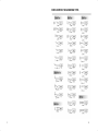
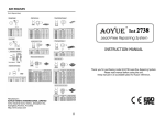
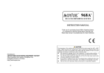
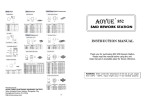
937/ 937+ Temperature�Controlled� Soldering�Station Instruction Manual Thank you for purchasing Aoyue 937 / 937+ temperature controlled soldering station. Please read the manual before using the unit. Keep manual in accessible place for future reference. Manufacturer: AOYUE TONGYI ELECTRONIC EQUIPMENT FACTORY Jishui Industrial Zone, Nantou, Zhongshan City, Guangdong Province, P.R.China http://www.aoyue.com 16 REPLACEMENT SOLDERING TIPS 2 15 BASIC TROUBLESHOOTING GUIDE PROBLEM 3: Soldering iron temperature is intermittent. TABLE OF CONTENTS Description: Display lights up but soldering iron temperature rises and falls uncontrollably. SOLUTION: ◆ ◆ Soldering iron plug may be loose from the receptacle unplug the soldering iron and reattach. Soldering iron cord may be damaged or loose and needs to be re placed or repaired. See trouble shooting soldering iron cords this manual. section of PROBLEM 4: The solder would not stick to the soldering pen. Description: Soldering iron is able to quickly melt solder but cannot cause the solder to attach to the tip. SOLUTION: ◆ Soldering iron tip may already be too dirty or oxidized . Please see ◆ our solder tip maintenance guide on how to clean soldering tips. Temperature could be set too high causing solder to quickly burn away, Please adjust to a more suitable lower temperature range. PROBLEM 5: Display and other problems not mentioned. Description: Display shows unreadable characters. Package Contents and Specifications……………….. 4 Care and Safety Precautions ………….………..…….. 5 Assembly Instructions ……………………………….... 6 Operating Instructions ………...……….…..…..…….. 7 Soldering Tip Care and Maintenance ……………….. 8 Tip Temperature Cleaning When not in use Hand piece Assembly …………. ………………….….… 9 Testing the heating element ……...…………………. 10 Troubleshooting Connections ….……..………..……. 11 Replacing soldering iron cord / Fuse ....………… 12 SOLUTION: ◆ Press the reset button or turn the unit off and then back on after a few seconds. 14 Basic Troubleshooting Guidelines ……………… 1314 Replacement Soldering Tips …………………………. 15 3 PACKAGE CONTENTS/ SPECIFICATIONS BASIC TROUBLESHOOTING GUIDE Please check if the listed parts below are included in the package: WARNING: To avoid personal injury or equipment damage, disconnect power cords before making any servicing to the equipment, or unless instructed otherwise in the trouble‐ shooting procedures. Aoyue 937/937+ 937 Main Station . . . . . . . . 1 unit Soldering Iron . . . . . . . . . 1 pc. Soldering Iron Stand (including Sponge) . . . . . . . . . 1 pc. PROBLEM 1: The unit has no power / display does not light up. Instruction Manual . . . . . . . . . 1 pc. 1. Check if the unit is switched ON. Power Cord . . . . . . . . . 1 pc. 2. Check the fuse. Replace with the same type of fuse if blown. 3. Check the power cord and make sure there are no disconnections. 4. Verify that the unit is properly connected to the power source. Power cord Additional precautions : ◆ Check internal circuitry for shorts that may cause the blown fuse. See “Troubleshooting Connections” . Soldering Iron stand PROBLEM 2: The temperature of the soldering iron is not rising. Description: Display lights up but soldering iron temperature is relative low and is not heating up. 937 / 937+ Power Consumption 45W Fuse 1A Output Voltage 24V Temperature Range 200—480 °C / 392—896°F Dimension Check for tangles of wires in the heating element causing it to short. See “Troubleshooting Connections” . Soldering Iron Main Station ◆ 110(w)×93(l)×168(h) mm Tip to Ground Resistance Less than 2 Ohm Heating Element Ceramic Heating Element SOLUTION: Soldering iron cord may be damaged and needs to be replaced or re paired. See “Troubleshooting Connections” of this manual. Heating element may be damaged and needs to be replaced see “Testing the Heating Element” and “Replacing the Heating Element” on this manual. *Design and specification might change without prior notice. 4 13 REPLACING SOLDERING IRON CORD /FUSE CARE and SAFETY PRECAUTIONS When cord is proven to be faulty follow the steps to replace the cord: 1. 2. 3. 4. 5. 6. 7. 8. 9. 10. 11. 12. Follow the steps in disassembling the hand piece. Make a brief illustration of wire configuration in the PCB. Unsolder the wires connecting the hand piece PCB and cord to gether. Unattached the grounding cord and grounding spring together. Detach the PCB from the cord by releasing the metal grips located at the bottom of the PCB . Slide out the main handle , soft grip pad and tail end of the hand piece. Insert the tail end and soft grip pad into the new cord. Insert the new cord thought the main handle. Solder the wires back into the PCB. Reattach grounding spring to the new cord. Bend the metal on the end of the PCB to grip the cord firmly. Follow Reassembly of hand piece steps to complete the process. For your own safety, be sure to comply with the following precaution. ● ● holder out Check if the fuse in use is blown. If blown/damaged, detach the high and automatically turns on when temperature dropped to a safe level. ● Reattach the fuse holder. Active fuse Fuse Holder ● ● Spare fuse holder Spare fuse Disconnect plug when not to be used for a long period of time. Turn off power during breaks. Use only genuine replacement parts. Soldering process produces smoke, make sure work area is well venti lated. ● Do not modify unit ● Never touch the element or tip of the soldering iron. They are very hot (about 400°C) and will give you a nasty burn. ● Take great care to avoid touching the mains flex with the tip of the iron. The iron should have a heatproof flex for extra protection. An ordinary plastic flex will melt immediately if touched by a hot iron and there is a serious risk of burns and electric shock. ● Always return the soldering iron to its stand when not in use. ● Work in a wellventilated area. The smoke formed as you melt solder ● 12 Handle with Care Never drop or sharply jolt the unit. Contains delicate parts that may break if unit is dropped. spare fuse and attach to the active fuse holder. ) Active fuse Thermal Protector Unit is equipped auto shutoff ability when temperature gets too ● The Fuse can be found at the back of the unit, it is incorporated into the AC power receptacle. If fuse is blown replace with same type fuse only. 1. Use a screw driver to pop open the fuse holder, slide the fuse 3. Temperature may reach a high of 480°C when turned on. Do not use near inflammable/flammable materials. Do not touch heated parts, can cause severe burns. Do not touch metallic parts near the Tip. Turnoff power and let unit cool before replacing parts. Checking/ Changing the fuse: 2. CAUTION: Misuse may cause injury and physical damage. is mostly from the flux and is quite irritating. Avoid breathing it by keeping your head on the side and not directly above of your work. Wash your hands after using solder. Solder may contain lead which is a poisonous metal. 5 TROUBLESHOOTING CONNECTIONS ASSEMBLY INSTRUCTIONS I. SOLDERING IRON HOLDER The 5 pin socket can be tested to detect faults in the handpiece: 1. Install solder wire to the solder iron holder. (Fig. 1) 2. Dampen the cleaning sponge with water, squeeze it dry and place it in its base. (Fig. 2) Pins 4 & 2 Pins 4 & 1 Pins 5 & 1 Pins 5 & 2 ∞ Before plugging in the hand piece conduct the conti nuity test as shown: ∞ If any of the combination registers a short re ∞ view the steps in “replacing the heating element” to ∞ ensure proper connections. Fig. 1 Failure to dampen sponge might damage the soldering tip. Fig. 2 II. SOLDERING IRON Follow the following direction to test for hand piece cord 1. Attach the soldering iron to the receptacle connector at the bot tom right area of the main unit. 2. Place soldering iron to the soldering iron stand as shown in Fig. 1 III. MAIN UNIT CONTROLS Warning: Ensure none of the above mentioned conditions are pre‐ sent before plugging in the hand piece. Failure to do so can dam‐ age the internal circuitry of the unit. Soldering iron must be placed in the iron holder when not in use. faults: Test 1: Rendering physical strain to the cord 1. Turn on the unit. 2. Set temperature to 480 °C. 3. Bend and straiten the entire length of the cord bit by bit. The heater lamp should always be lit while doing so. If the heater lamp becomes intermittent the cord is faulty and should be re 1. Plug the power cord into a receptacle with ground. placed. Digital display Digital display Digital Control Temperature adjustment knob Note: the Heater lamp will blink if the temperature of the soldering iron tip has reached the set temperature i.e. 480°C. this is not an indication of a faulty cord. Test 2: Resistance test 1. Follow the steps in disassembling the hand piece . Main power switch Hand piece receptacle 937 Controls 6 937+ Controls 2. Test for continuity between the pins and colored wires at the hand piece PCB, all matching contacts at the PCB and wires should reg ister 0 to 2 Ω. 11 TESTING THE HEATING ELEMENT OPERATING INSTRUCTIONS To test if the heating element is in working condition: Cool down assembly to room temperature before continuing the tests below: 1. Follow “disassembling the hand piece” guide. 1. Follow procedures shown in the “Assembly Instructions”. 2. Turn on the unit. 3. The Digital display will initially display the current set temperature, 2. Do the following tests on the hand piece PCB board: after a few seconds it would switch to displaying the actual tem ◆ Resistance value of heating element (RED) 18 — 23 Ω perature. Resistance value of sensor (blue) 2.5 — 3.5 Ω After testing check results with the following: If the resistance value is not as stated above replace the heating element. If a 0 Ω or infinite resistances are measured check for shorts or open circuits. Itermittent readings can also be caused by cold solder double check solder points if the heating element has recently been replaced. ◆ ◆ ◆ ◆ ◆ Heating element (RED) 4. For 937: Turning the control knob clockwise increases the desired (SET) temperature settings, while turning the knob counter clockwise decreases the desired (SET) temperature settings. The display would increase and decrease accordingly showing the SET temperature. If the knob is left unmoved, the display would switch from showing the SET temperature to showing the actual tempera ture at the tip of the soldering iron. 5. For 937+: Pressing the up button increases the desired (SET) temperature settings, while pressing the down button decreases Sensor (BLUE) the desired (SET) temperature settings. The display would increase and decrease accordingly showing the SET temperature. If the but tons are all depressed, the display would switch from showing the Heating element SET temperature to showing the actual temperature at the tip of the soldering iron. The button with the asterisk * marking is used Test the resistances of the following configurations at the 5 pin socket: to quickly reset the device to the default temperature setting. Pins 1 & 2 18 to 23 Ω Pins 4 & 5 2.3 to 3.5 Ω Pin 3 & solder tip Below 2 Ω 6. The display would show the letters “OFF” if the unit has detected that the soldering iron and the main unit are not connected se curely or is not connected. If this is displayed, turn off the unit and 5 Pin Socket reattach firmly the soldering iron to the receptacle at the main unit. 10 7 SOLDER TIP CARE and MAINTENANCE Tip Temperature HAND PIECE ASSEMBLY The hand piece may be disassembled for troubleshooting and we suggest you to use the lowest *possible* tip temperature when sol dering. This not only prolong life of the tip, it also quickens heat recov repair: 1. Turn off main station and unplug from power source. 2. Detach the Soldering Iron Receptacle (“15” ) from the main unit. 3. Turn the Copper Nut, (“1” ) counter clockwise to loosen it. ery and decreases harm to sensitive components. 4. If the tip temperature is too high, it decreases the life of the tip. So Cleaning The soldering iron tip should be cleaned after use by wiping it on the damp sponge found in the soldering iron stand, this is to get rid of burnt solder or fluxes that causes oxidation on the tip. If the tip has oxi dation, apply solder and wipe using the damp sponge, repeat these steps until oxidation is removed. Regular cleaning is also needed when tips are used for prolonged period of time (remove tip from soldering iron and clean it once a week). The solder tips are chrome electroplated on the surface and should be bright silver with no flux residue or solder on it. If the tip shows disfiguration or has rust on it. Change the tip. 5. Pull out the Tip Enclosure (“2” ), the Solder Tip (“3” as ) , and the Tip Lock (“4” ). Turn the Plastic Nut (“5” ) counter clockwise to release it from the 6. main body. Push out the Heating Element (“6” ) via the wire Cord (“14” ). Remember to tin the tip after cleaning in preparation for the next use. When Not in Use If a soldering iron does not have a thin consistent layer or solder Follow these steps to reassemble the hand piece: 1. Slide in hand piece PCB into the main handle. Be sure to secure the PCB over the entire surface, the tip has not been properly tinned. When you are not using your iron, make sure you leave a large lump of solder on the tip. This maintains the tinning on the tip, and the tip will last much longer. Many technicians mistakenly clean the tip before they put the iron into the holder. Leave the solder on the tip to protect it. in the notch at the mouth of the main handle. 2. Attach the front module “5” to the main handle. 3. Slide in the Tip holder “4”. Make sure the smaller end is inserted first as seen in the illustration below. 4. Insert the soldering iron tip “3” as seen below. 5. Secure the tip by inserting the tip enclosure “2” and nut ”1” securely. 6. Reattach the hand piece plug “15” to the receptacle at the main station. 7. Recalibrate the soldering iron, see guide on tip care and maintenance section of this manual. 8 9