1
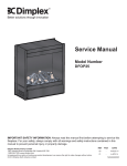
en Service Manual Coffee Machine Essenza C91 (WIK) Essenza D91 (WIK) Contents Replacing compact brewing unit _________________________ 21 Wiring diagram Europe (230V / 50 Hz) ___________________ 22 Preface______________________________________________ 3 General _____________________________________________ 3 Nespresso technical website_____________________________ 3 Content updates ______________________________________ 3 Function Tests _____________________________________ 23 Measuring flow rate (1) ________________________________ 23 Measuring flow rate (2) ________________________________ 24 Checking for leaks and pump pressure (1) _________________ 25 Checking for leaks and pump pressure (2) _________________ 26 Measuring coffee temperature___________________________ 27 Protective earth continuity test (1) ________________________ 28 Protective earth continuity test (2) ________________________ 29 Protective insulation test (1) ____________________________ 30 Protective insulation test (2) ____________________________ 31 Protective insulation test (3) ____________________________ 32 General Safety Notes ________________________________ 4 Main Components ___________________________________ 5 Overview ____________________________________________ 5 Overview of rating plates________________________________ 6 Water circuit _________________________________________ 7 Technical data ________________________________________ 8 Operation ___________________________________________ 9 Preparation __________________________________________ 9 Fill water system _____________________________________ 10 Making coffee _______________________________________ 11 Empty water system __________________________________ 12 Coffee machine status_________________________________ 13 Maintenance ________________________________________ 33 Descaling (1) ________________________________________ 33 Descaling (2) ________________________________________ 34 Daily care and final cleaning ____________________________ 35 Troubleshooting ____________________________________ 14 Spare Parts _________________________________________ 37 Checking the machine on receipt ________________________ 14 Repair accessories ___________________________________ 37 Spare parts C91______________________________________ 38 Repair ______________________________________________ 16 Safety instructions____________________________________ 16 General disassembly__________________________________ 16 Replacing NTC ______________________________________ 17 Replacing thermoblock ________________________________ 18 Replacing pump _____________________________________ 19 Replacing electronic control board with button prints _________ 20 Service Manual C91 / D91 Notes ______________________________________________ 40 2 Version 1.0 en Preface General Nespresso technical website The purpose of this service manual is to provide the service personnel with all neces sary information with regards to correct handling, maintenance and repair of the coffee machines C91 and D91. Visit the Nespresso technical website periodi cally to check for upgrades, technical modifi cations, counter measures etc. for this coffee machine: https://business.nespresso.com This manual should be used by the techni cians as a valuable aid to guarantee the permanent readiness for use of the machine. In order to take full advantage of all the func tions, it is absolutely necessary to follow the instructions in this manual. Service Manual C91 / D91 Access is restricted and can be obtained by asking your Nespresso technical contact person. Content updates The version number of this service manual is printed on the lower right corner of the page. Version 1.0 First released service manual version. Please keep this manual together with the corresponding service documentation. This way you are assured to have the necessary information. 3 Version 1.0 en General Safety Notes Risk of fatal electrical shock and fire! Mains voltage inside the coffee machine. • Unplug appliance before cleaning. • Never clean wet or immerse plug, cord or appliance in any fluid. • Disconnect the mains plug before disassembly the appliance must be free of voltage. Example illustrations of typical devices: As an additional safety measure, the use of a residual current device (RCD), also called a ground fault circuit interrupter (GFCI), in the repair centre is highly recommended. This device does not protect against electrical shock due to contact with both circuit conductors. Use a GFCI with a trip level of 4 6 mA (USA) resp. a RCD with a trip level of 15 30 mA (Europe). A trip level above 30 mA provides only very limited protection against harm from an electric shock. Danger of burns! Hot parts and water under pressure inside the coffee machine (particu larly in the thermoblock). • Let coffee machine cool down before cleaning or disassembly. Service Manual C91 / D91 1) RCD protected socketoutlet 2) Plugin RCD unit 3) GFCI socket 4) Plugin GFCI 4 Version 1.0 en Main Components Overview 1) Closing handle 2) Cover 3) Compact brewing unit (TCBU) 4) Capsule inlet 5) Side panel 6) On/Off button 7) Coffee outlet 8) Coffee button, back lighted 9) Container for used capsules 10) Drip grid 11) Drip tray 12) Lower chassis 13) Thermoblock WIK 14) Electronic control board 15) Pump 16) Water tank connector 17) Upper chassis 18) Water tank Service Manual C91 / D91 5 Version 1.0 en Main Components Overview of rating plates The rating plate can be found at the underside of the coffee machine. It is of varying design depending on the brand and carries the following information: • Machine type • Voltage and power rating • Manufacturing country • Conformity with RoHS guidelines • Special disposal icon • Sign of conformity (CE) • Bar code • Serial number This overview shows examples of various brands and is subject to alterations. Serial number codification Example: 10190C91x0002782090 10190 production date: 190 th day of year 2010 C91 machine type x production site 0002 incremental number per production day 7 machine partner codification 8 voltage 2 mains plug version 09 colour version 0 checksum number Service Manual C91 / D91 6 Version 1.0 en Main Components Water circuit 1) Water tank 2) Water tank valve and connector 3) Pump 4) Thermoblock 5) Compact brewing unit (TCBU) 6) Coffee outlet Service Manual C91 / D91 7 Version 1.0 en Main Components Technical data C91 Mains EUR Approvals Cable length 230V / 50 Hz CEconform approx. 1.1 m Energy consumption (CECED / FEA 2009 method) Energy efficiency class level Daily energy consumption Annual energy consumption A 129 Wh 47.09 kWh Pump data Pump pressure max. permissible 19 bar ± 2 bar during coffee preparation 9 13 bar (depending on brand of coffee) Various data Preheating time approx. 50 sec. Safety temperature (thermal cutoff) 167° C Coffee temperature at outlet 86° C ± 3° C Flow performance 120 240 ml/min. at 12 bar Weight of machine (without water) D91 approx. 3 kg Capacities Water tank Drip tray Capsule container 0.9 l approx. 100 ml 10 14 pcs. Power consumption (at all voltages and frequencies) Total power consumption Thermoblock Pump (old/new version) Service Manual C91 / D91 8 1’260 W 1’200 W 48/65 W Version 1.0 en Operation Preparation 1 1. Fill tank with water. 2. Insert water tank in coffee machine. 3. Switch on machine by pressing the On/Off button. 4. Position receptacle with a capacity of min. 100 ml under coffee outlet. 3 Do not insert a capsule yet. 2 5. Wait until machine is ready (coffee button stops blinking). 6. Press coffee button to rinse coffee outlet. 7. Press coffee button again to stop rinsing when receptacle is filled. 4 5 6 Service Manual C91 / D91 9 7 Version 1.0 en Operation Fill water system 2 If the coffee machine cannot pump water although there is water in the tank, the water circuit may be empty. 5 4 Procedure to fill water system: 1. Perform steps 1 to 5 for preparation (see page 9). 2. Open closing handle in vertical position. 3. Press coffee button. 4. Press and hold closing handle to rear end position. 5. Observe capsule inlet for appearing water. 6. Press down closing handle immediately when first droplets are visible. 7. Press coffee button again to stop water flow. 3 6 7 Service Manual C91 / D91 10 Version 1.0 en Operation Making coffee 1. Open closing handle. 2. Insert capsule. 3. Press down closing handle completely. 4. Position cup under coffee outlet. 5. Press coffee button. 6. Press button again to stop coffee flow when cup is full. 7. Briefly open closing handle after coffee preparation and eject capsule into capsule container. 1 3 2 5 4 7 6 Service Manual C91 / D91 11 Version 1.0 en Operation Empty water system 5 After operation, residual water remains in the water circuit. This residual water can be removed before a longer period of nonuse, for frost protection, before repair and following shipping. 1. Empty water tank. 2. The machine is switched off: Press and hold On/Off button. 3. Simultaneously press coffee button three times. 4. Release both buttons. The coffee button starts blinking fast and the thermoblock heats up, evaporating the residual water. 5. Open closing handle and hold it in opened position. 6. After coffee button stops blinking, press down closing handle completely. 7. Empty drip tray. 1 2 4 3 6 7 After this procedure the machine is blocked for approx. 10 minutes (till thermoblock temperature < 100° C). Service Manual C91 / D91 12 Version 1.0 en Operation Coffee machine status After pressing the On/Off button, an automatic self test is performed to check if the NTC is connected, the NTC is short circuited, the thermoblock reaches the standby temperature within 2 minutes in brewing mode. A detected failure is indicated by the back lighted coffee button as well as the operating modes listed in the following table. Service Manual C91 / D91 ( 1 H z ) Operating mode Coffee button LED signal Off off Heat up (coffee) blinking slow Ready on System too hot blinking fast Brew coffee / rinse blinking slow Heat up (descaling) blinking fast Descaling ready blinking fast Pump on (while descaling) blinking fast Emptying water system blinking fast Failure blinking three times fast 13 Version 1.0 en Troubleshooting Checking the machine on receipt The receipt check enables you to rapidly locate faults on the machine and to initiate Check procedure 1 Check appliance for visible damage appropriate repair action. Follow the check procedure. Symptoms Repair any faults found and check if the machine is operating perfectly. Action / repair work 1.1 Parts of housing broken or damaged YES Replace parts if necessary NO Go to point 1.2 1.2 Mains cable damaged YES Replace mains cable NO Plug machine to the mains and go to point 2.1 Further action / repair work YES Go to point 2.2 2.1 Closing handle works correctly 2 Check mechanical elements 3 Fill water tank 4 Press On/Off button to perform automatic self test YES Screw on closing handle screws at defined NO It is hard or impossible to close the closing handle torque or replace CBU (see page 22) NO Replace the CBU 2.2 Is the capsule correctly ejected? YES Go to point 3 NO Replace TCBU 3.1 Water tank is leaking YES Replace water tank NO Go to point 4 4.1 Machine is not working (no function) YES a) Check if mains cable is functional YES Go to point b) NO Replace it YES b) Check if On/Off button is functional YES Go to point c) NO Replace it YES c) Check if pump is working (press coffee button) YES Go to point f) NO Go to point d) YES d) Check if coffee button is functional YES Go to point e) NO Replace it YES e) Check if pump's thermal fuse (128°C) is defective YES Replace pump (see page 20) NO Go to point f) YES Replace thermal fuse and if necessary YES f) Check if thermoblock’s thermal fuse (167°C) thermoblock too (see page 19) is defective NO Go to point g) YES g) Check if electrical wires are functional YES Replace electronic mainboard (see page 21) NO Replace defective(s) wire(s) NO Go to point 4.2 Service Manual C91 / D91 14 Version 1.0 en Troubleshooting Check procedure 4 Press On/Off button to perform automatic self test (continued) Symptoms Action / repair work YES Check if thermoblock heating element is func 4.2 Backlighted coffee button blinks at irregular tional intervals NO Self test ok. Go to point 5 5.1 No coffee at outlet 5 Check coffee temperature while preparing a coffee (see page 29) 6 Check for leaks and check flow rate (see pages 25 and following) YES Replace NTC (see page 18) NO Replace thermoblock (see page 19) YES a) Water system is empty YES Fill water system (see page 10) NO Go to point b) YES b) Pyramid plate is clogged YES Replace TCBU (see page 22) NO Go to point c) YES c) Machine is blocked by scale YES Descale machine (see page 36) NO Go to point 5.2 5.2 Temperature is too low (less than 83°C) YES Descale the machine (see page 36) NO Go to point 5.3 5.3 Temperature is too high (more than 89°C) YES Change NTC (see page 18) NO Go to point 6 6.1 Leakage at extraction system YES Replace TCBU (see page 22) NO Go to point 6.2 6.2 Leakage at tubes connection YES Replace defective tube and seal NO Go to point 6.3 YES Machine is scaled YES Descale machine (see page 36) NO Replace pump NO No trouble found during the check procedure. Contact Nespresso Technical Correspondant for further details in order to take decision 6.3 Flow rate out of range 7 Descaling process (if needed) Further action / repair work 7.1 Machine scaled YES Descale machine (see page 36) NO Go to point 8 8 Final cleaning (see page 38) End of check procedure Service Manual C91 / D91 15 Version 1.0 en Repair Safety instructions Risk of fatal electrical shock! Mains voltage inside the coffee machine. Disconnect the mains plug before disassembly the coffee machine must be free of voltage. Danger of burns! Hot parts and water under pressure inside the coffee machine (ther moblock in particular). Let coffee machine cool down before disassembly. General disassembly Tool: Torx screwdriver for security screws, PinTX 10 Illustration of a PinTX screw head Empty water system if necessary (see page 12). Service Manual C91 / D91 Procedure: 1. Remove water tank (15) and drip tray (5) together with drip grid (4) and capsule container (6). 2. Remove 2 screws (20) on the front side of the machine. 16 3. Place machine on the repairing/service holder device (see page 42). 4. Remove 6 screws (20) on the bottom of the machine. 5. Swing out and remove both side panels (1). 6. Remove lower chassis (2). Version 1.0 en Repair Replacing NTC Tools: Torx screwdriver PinTX10 Openended spanner 9 mm AF Torque wrench Procedure: 1. Follow general disassembly (see page 17). 2. Remove PCB housing (301). 3. Unplug NTC connector from electronic control board (300). 4. Remove defective NTC temperature sensor (219) from thermoblock (215) and replace it with a new one. 5. Assemble in reverse sequence. Reuse spring lock washer (220) and tighten new NTC temperature sensor (219) with torque wrench (140 160 Ncm). Service Manual C91 / D91 17 Version 1.0 en Repair Replacing thermoblock Tools: Torx screwdrivers PinTX10, TX20 Openended spanner 9 mm AF Torque wrench Procedure: 1. Follow general disassembly (see page 17). 2. Remove 3 screws (19) and separate ther moblock assembly from upper chassis (3). 3. Remove screw (222) and separate ther moblock from its support (216 + 217). 4. Remove 2 screws (224) and separate thermal fuses (parts of cord set 304) from thermoblock. 5. Remove PCB housing (301). 6. Unplug NTC connector from electronic control board (300). 7. Remove NTC temperature sensor (219) from thermoblock. 8. Remove clips (228) and 2 hose connec tors (211+212) from thermoblock. 9. Remove ground wire and electrical connections from thermoblock. 10. Replace thermoblock (215). 11. Assemble in reverse sequence. Use a torque wrench (140 160 Ncm) to tighten NTC temperature sensor (219) with spring lock washer (220). Service Manual C91 / D91 18 Version 1.0 en Repair Replacing pump Tools: Torx screwdriver PinTX10 Longnose pliers Blade screwdriver, no. 7 Procedure: 1. Follow general disassembly (see page 17). 2. Remove clip (227), hose (205) and Oring (206). 3. Remove angled hose (204). 4. Release pump (208) first from rubber strap (213) at the side of the angled hose. 5. Remove electrical connections from pump. 6. Release pump from second rubber strap (213). 7. Replace defective pump (208). 8. Attach new pump (208) to one rubber strap with corner connector (209) first. 9. Plug in electrical connections on pump. Check for correct wiring of pump. 10. Attach pump to second rubber strap. 11. Insert new Oring (226), mount hose (205) and clamp (227). 12. Mount angled hose (204). Service Manual C91 / D91 19 Version 1.0 en Repair Replacing electronic control board with button prints Tools: Torx screwdriver PinTX10 The service engineer must be earthed using an earthing strap! Only touch button prints with dedi cated gloves to avoid oxydation. Procedure: 1. Follow general disassembly (see page 17). 2. Detach prints of On/Off button (13) and coffee button (14) from upper chassis (3). 3. Remove 2 screws (19) and lift cover (7) at the front side to threadout cables with button prints. 4. Remove housing (301) from electronic control board (300). 5. Unplug NTC connector and all wires from electronic control board (300). 6. Remove 2 screws (20) and replace defect electronic control board with button prints. 7. Assemble in reverse sequence. Check for correct wiring of electronic control board (see page 23). Service Manual C91 / D91 20 Version 1.0 en Repair Replacing compact brewing unit Tools: Torx screwdriver PinTX10 Blade screwdriver no. 4 Longnose pliers Torque wrench Procedure: 1. Remove water tank (15) and drip tray (5) together with drip grid (4) and capsule container (6). 2. Place machine on the repairing/service holder device (see page 42). 3. Remove 4 screws (20) on the bottom of the machine. 4. Swing out and remove both side panels (1). 5. Remove 2 screws (21) and pull off closing handle (8). 6. Remove 2 screws (19) at the front and 1 screw (19) at the back to detach cover (7). C91 machine: All screws have the same lenght. D91 machine: The screw at the back is longer than those at the front. 9. Remove clip (227) and hose (206) with O ring (226) from compact brewing unit. 7. Unlatch coffee outlet (9) from compact 10. Assemble new compact brewing unit brewing unit (100) with a blade screwdriver. together with new coffee outlet (9) in 8. Remove 4 screws (19) and detach reverse sequence. compact brewing unit (100). Replace Oring (226). Service Manual C91 / D91 21 Tighten new closing handle screws (21) with a torque of 200 Ncm. Version 1.0 en Repair Wiring diagram Europe (230V / 50 Hz) 1) Heat sink 2) Print for On/Off button 3) Print for coffee button with LED 4) NTC temperature sensor 5) Thermal fuses on thermoblock 6) Thermal fuse on pump 1 2 4 3 5 6 Service Manual C91 / D91 22 Version 1.0 en Function Tests Measuring flow rate (1) Procedure: 2 1 3 1. Fill and insert water tank. 2. Open closing handle. 3. Insert connecting unit of pressure adapter into capsule bay. 4. Push back sealing cone into capsule cage. 5. Insert fixation unit of pressure adapter into capsule bay. 6. Press down operating lever. 6 Continued on next page. Service Manual C91 / D91 23 Version 1.0 en Function Tests Measuring flow rate (2) Procedure (continued): 7. Connect pressure hose to pressure tester. 8. Position measuring beaker underneath exit tube of pressure tester. 9. Switch on machine. 10. Press coffee button after heatingup. 11. Open valve fully till water begins to flow. 12. Close valve slowly until 12 bar are indi cated. The manometer must be observed continuously and the pressure regu lated using the valve if necessary. With increasing temperature the pressure also increases, if neces sary readjust the pressure to 12 bar. 13 7 11 12 9 10 8 14 13. Perform measurement for approx. 30 sec. 14. There must be at least 60 120 ml water in the measuring beaker. Notice: With a flow of < 60 ml the pump is defective or there is a leak in the system. Large fluctuations in the pressure gauge readings (± 4 bar) during measurement are indicative of a defective pump. Service Manual C91 / D91 24 Version 1.0 en Function Tests Checking for leaks and pump pressure (1) 2 3 The following components are checked for leaks: Compact brewing unit (TCBU) Hose connections Thermoblock Pump 4 1 Preparation (unplug machine from mains): 1. Remove right side panel. 2. Open closing handle. 3. Insert connecting and fixation unit of pres sure adapter into capsule bay (refer to page 25). 4. Press down operating lever. 5. Position pot underneath exit tube of pres sure plug. 6. Fill and insert water tank. 7. Connect mains cable. Dangerous voltage inside coffee machine! Do not touch any live part while performing checks. Hot, pressurized parts inside coffee machine! Do not touch any hot part while performing checks. Wear safety glasses during inspection. 6 7 5 Continued on next page. Service Manual C91 / D91 25 Version 1.0 en Function Tests Checking for leaks and pump pressure (2) 9 Procedure (continued): 8. Switch on machine. Press coffee button after heatingup. 9. Open valve and leave water to run out for approx. 10 sec. 10. Fully close valve. The pressure will rise rapidly initially and stabilise between 16 19 bar (check of pump pressure). 10 8 8 The pressure will rise slowly due to the temperature increase. If the pressure exceeds 23 bar, the machine has to be switched off and pressure released through the pres sure valve. 11. Perform visual and acoustic checks on all pressurized connections. The pump must not be in operation for longer than 50 sec. without water flow. 13 11 12 12. Switch off machine. 13. Open valve to empty pressure gauge. Service Manual C91 / D91 26 Version 1.0 en Function Tests Measuring coffee temperature Procedure: 1. Press On/Off button to switch on machine. 2. Position measuring beaker underneath coffee outlet. 3. After warming up, press coffee button. 4. Preheat coffee outlet for 10 sec. with hot water. 5. Empty measuring beaker. 6. Insert a capsule (Cosi is the most suit able). 7. Press coffee button. 8. Wait until 20 ml coffee has flown in the measuring beaker. 9. Measure the coffee temperature approx. 5 10 mm below the outlet opening. 1 4 3 2 6 Coffee temperature should be approx. 86 °C ± 3 °C (187 °F ± 5.4 °F). 9 7 5 8 Service Manual C91 / D91 27 Version 1.0 en Function Tests Description Protective earth continuity measurements are What coffee machine model has to be test made between the protective earth terminal of the power plug and ed and when? the thermoblock, This test is necessary all conductive, touchable parts of the coffee for class 1 equipment (threewire power machine where dangerous voltage could cord with protective earth) occur if the basic insulation was to fail. after a repair whenever the housing was opened and for example a general disas This test assures that sembly was performed. the ground (earth) connection does not have an interruption between the power Therefore all coffee machine models have to plug and the thermoblock be tested after opening the housing, except the permissible ground resistance is less countryspecific models without a protective than 0.3 Ohms (with a test current of earth connection. 200 mA DC). Protective earth continuity test (1) General Legal regulation In case of a repair/modification of the coffee machine, the repair centre is bound by law to protect the user/consumer by restoring the regular condition of the appli ance and performing the respective tests according to EN/IEC 603351 “Safety of household and similar electrical appliances” and national regulations (e.g. DIN VDE 0701). Service Manual C91 / D91 Test equipment Special test equipment is needed that complies with the regulations to perform protective earth continuity measurements. Detailed requirements and tolerances must be verified by your local authorities or measure ment supplier in any case. Ask Nespresso for recommenda tions about test equipment. 28 Test report For legal reasons a repair or test report should be prepared and filed with following informa tion customer (name, address) type and serial number of coffee machine date of repair/test(s) performed test(s)/measuring value(s) used test equipment signature Test sequence Danger of electrocution! Do not plug in the coffee machine during the protective earth conti nuity test. Read and observe safety instruc tions in user manual of test equip ment. This test sequence is not applicable for coffee machines with twowire power cords (without ground pin). Continued on next page. Version 1.0 en Function Tests Protective earth continuity test (2) Test sequence (continued): 1. Connect black measuring cable to ground pin of power plug with an alligator clip (example shown: Swiss power plug). 2. Switch on test equipment and select protective earth continuity test. 2 1 Symbolic illustration of test equip ment. 3. Touch thermoblock through one of the marked holes with tip of red test probe. 4. Press "measure" button and read off displayed resistance. The resistance must be lower than 0.3 Ohm. 5. Fill in measured value in a test report. Proceed with protective insulation test before reassembling the housing of the coffee machine. 4 What to do if the protective earth continuity test fails Check ground wire connection on thermoblock (refer to wiring diagrams on page 23). Service Manual C91 / D91 3 29 Version 1.0 en Function Tests Protective insulation test (1) Perform the protective earth conti nuity test at first, if it is mandatory. What is the protective insulation test about? This test is necessary for class 1 and 2 equipment (with/without protective earth), after a repair whenever the housing was opened and for example a general disas sembly was performed. General Legal regulation In case of a repair/modification of the coffee machine, the repair centre is bound by law to protect the user/consumer by restoring the regular condition of the appli ance and performing the respective tests according to EN/IEC 603351 “Safety of household and similar electrical appliances” and national regulations (e.g. DIN VDE 0701). Description The insulation test assures that wiring and insulation of the coffee machine fullfill the normative Service Manual C91 / D91 requirements after a repair, rates the insulation capability of the coffee machine, is a very dangerous test because of a high test voltage (500 V DC). For the insulation test, phase and neutral wire are shunted at the power plug. Then a test voltage is applied between phase/neutral and selected parts of the coffee machine. Test equipment Special test equipment is needed that complies with the regulations to perform insu lation and withstanding voltage tests. Detailed requirements and tolerances must be verified with your local authorities or measurement supplier in any case. Ideally the test equipment has a national power socket for testing, so that the coffee machine can plugged in directly. Otherwise a special shunt is necessary to connect the phase and neutral pin of the coffee machine’s power plug. Ask Nespresso for recommenda tions about test equipment. Test report For legal reasons a repair or test report should be prepared and filed with following informa tion customer (name, address) type and serial number of coffee machine date of repair/test(s) performed test(s)/measuring value(s), test points used test equipment signature Test sequence Danger of electrical shock/short circuit! • Do not plug in the coffee machine during insulation test. Danger of electrical shock! • Do not touch tip of test probes. • Do not touch metallic parts of coffee machine during test. • Read and observe safety instructions in user manual of test equipment. Continued on next page. 30 Version 1.0 en Function Tests Protective insulation test (2) Test sequence (continued): 3 1. Connect the phase and neutral pin of the power plug together with a test adapter (procured by the repair centre). 2 A Swiss power plug is shown here as an example. 2. Connect the black measuring cable to the test adapter (see image). 1 Use a short circuit plug or special alligator clips etc. as substitute for this test adapter. 3. Switch on test equipment and select an insulation test voltage of 500 V DC. Symbolic illustration of test equip ment. 4. Touch thermoblock through one of the marked holes with tip of red test probe. 5. Press "measure" button and read off displayed insulation resistance or test result. 5 Continued on next page. Service Manual C91 / D91 4 31 Version 1.0 en Function Tests Protective insulation test (3) Test sequence (continued): The insulation resistance must be higher than 300 kOhm (300,000 Ohm). Some test equipment displays test passed or failed instead of the insu lation resistance. 7 6. Fill in measured value in a test report. 7. Touch closing handle screw with red test probe. 8 Do not scratch surface of closing handle with probe tip. 8. Press "measure" button. 9. Read off displayed insulation resistance or test result. The insulation resistance must be higher than 300 kOhm (300,000 Ohm). 10. Fill in measured value in a test report. 11. Switch off test equipment. 12. Short red with black test probe to make sure that test voltage is discharged. What to do if the insulation test fails Risk of damage! A sparkover can damage the elec tronic control board and sensors etc. Assume that the coffee machine is defect after a failed insulation test. Check wiring and locate fault. After fault clearance proceed with trouble shooting check list (see page 14). Service Manual C91 / D91 32 Version 1.0 en Maintenance Descaling (1) Only use Nespresso decalcifier never vinegar! Decalcifier is aggressive to surfaces. Immediately clean drops of descaling solution. 2 Preparation: 3 1 1. Switch off machine. 2. Check that there is no capsule in inlet and close handle. 3. Remove drip grid. Empty drip tray and capsule container. 4. Reinsert drip tray and place a pot on it. Carefully read safety instructions on decalcifier package. 5. Fill measuring jug with 0.5 l fresh, potable water and pour 0.1 l descaling fluid in it. 6. Fill descaling solution in water tank. Reinsert water tank. 7. Press On/Off button and coffee button simultaneously for at least 3 seconds to switch on machine and start descaling mode (fast blinking coffee button). Descaling: 6 7 5 9 7 8 4 8. Press coffee button to start pump. 9. Let entire descaling solution pass through coffee outlet. Service Manual C91 / D91 33 Version 1.0 en Maintenance Descaling (2) 10. Fill water tank again with descaling solu tion from pot. 11. Repeat descaling procedure one more time: Press coffee button and let entire descaling solution run through. 10 Rinsing: 12. Empty pot. 13. Rinse water tank thoroughly and fill it with fresh water. 14. Place pot on drip tray. 15. Press coffee button to start pump. Let complete content of water tank run through coffee outlet. 16. Switch off machine. Descaling is completed. 17. Remove and empty pot. 18. Clean machine. 11 12 18 13 16 17 14 Service Manual C91 / D91 15 34 Version 1.0 en Maintenance Daily care and final cleaning Risk of fatal electrical shock and fire! Never clean wet or immerse plug, cord or appliance in any fluid. Unplug appliance and let it cool down to avoid burns. 1 2 Never use hard cleaning brushes and/or cleaning agents that contain aggressive or chemical components resp. solvents. Do not put any part in a dishwasher. Preferably use only a damp cloth or sponge and a mild cleaning agent if necessary. Do not use a brush to clean the water tank it could be scratched. Procedure: 1. Eject capsule. 2) Empty capsule container. 3) Empty water tank and drip tray. 4) Clean water tank and drip tray. 3 4 Service Manual C91 / D91 35 Version 1.0 en Maintenance 5 6 Procedure (continued): 5) Fill tank with fresh water. 6) Reassemble coffe machine. 7) Press On/Off button. Wait till coffee button stops blinking. 8) Press coffee button and rinse coffe outlet for 10 sec. 9. Clean coffee machine. 7 9 8 Service Manual C91 / D91 36 Version 1.0 en Spare Parts Repair accessories Pos. EFR No. 1 3 Component Repairing/service holder device (for C91or D91) 1 * 2 42213 Manometer 3 60460 Pressure adapter G4 64373 Spare part seal G4 * Repair accessories only available at Nespresso. Please ask your Nespresso technical contact person. Manometer and pressure adapter are avail able at Eugster Frismag AG 2 Service Manual C91 / D91 37 Version 1.0 en Spare Parts Spare parts C91 Service Manual C91 / D91 38 Version 1.0 en Spare Parts Pos. WIK P/N Pos. WIK P/N 15+16+17+18 9310132000 C91 Water tank A Part Description 212 9310133800 C91/D91 Hose connector 55° 15+16+17+18 9310134800 D91 Water tank B 13 5040023600 C91 On/Off button silicon 6 9310133700 C91 Capsule Container A 13 5040044000 D91 On/Off button silicon 6 9310135300 9310154900 D91 Capsule Container B 14 5040023300 C91 Coffee button silicon 4 C91 Drip Grid A 14 5040044100 D91 Coffee button silicon 4 9310155000 D91 Drip Grid B 300 1350009200 C91/D91 PCB assembly 230V Part Description 5 9310134600 C91 Drip Tray A Nespresso printed 301 9310133900 C91/D91 PCB housing 5 9310135600 D91 Drip Tray B Nespresso printed 302 9310134000 C91/D91 PCB base 5 9310161000 D91 Drip Tray B DeLonghi printed 225 5040038600 C91/D91 Isolation spout angular 5 9310161100 D91 Drip Tray B Magimix printed 5 9310161200 D91 Drip Tray B Koenig printed 9310134100 C91/D91 Thermoblock assembly 230V 5 9310161300 C91 Drip Tray A Turmix printed 5 9310161400 C91 Drip Tray A Krups printed 215+216+217+ 218+221+222+ [2x(223+224)]+ [2x(wire+fuse)] 8 9310140500 C91/D91 Closing handle 219 1190000700 C91/D91 NTC 21 5030039900 C91/D91 Torx head screw ST3.9x17 220 5010026500 C91/D91 Spring lock washer for NTC 7 9310133500 C91 Cover A 304 2010069000 C91/D91 Cordset VDE plug 7 9310134700 D91 Cover B 200+201+202+ 203+204 9310132200 C91/D91 Water tank connector assembly 100 9310132100 C91/D91 TCBU assembly 9+10 9310133000 C91 Coffee outlet assembly 9+10 9310134900 D91 Coffee outlet B assembly 3 9310133600 3 9310135000 214 9310134200 C91/D91 Pump fixation 9310133100 C91/D91 Pump 230V assemblyfuse128°C connec C91 Upper chassis A 208+209+ 210+213+ Fuse 128°C D91 Upper chassis B 211 9310134300 C91/D91 Hose connector 90° (TB/pump) C91 Color box C91 Nespresso 1 9310131800 C91 Side panel A 8020182200 1 9310135100 D91 Side panel B 8020182600 D91 Color box D91 Nespresso 2+11 9310131900 C91 Lower chassis Aelastic stop rubber C91 Master carton 2+11 9310135200 D91 Lower chassis Belastic stop rubber 8990055500 8990055500 226 5040037700 C91/D91 Oring (3,5x2) 8100117801 C91 Instruction for user C91 Nespresso D91 Instruction for user D91 Nespresso D91 Master carton 206 9310132400 C91/D91 Hose assembly 225mm (TB/TCBU) 8100118201 205 9310132300 C91/D91 Hose assembly 120mm (Pump/TB) 8050004300 C91 Polyfoam tray left 207 5040021800 C91/D91 Cover Hose (TB/TCBU) C91 Polyfoam tray right 227 4010006300 C91/D91 Connector clip 4mm 8050004400 8050004300 228 4010006200 C91/D91 Connector clip 5mm 8050004400 D91 Polyfoam tray right Service Manual C91 / D91 39 D91 Polyfoam tray left Version 1.0 en Notes Service Manual C91 / D91 40 Version 1.0 en