1
User’s Manual Includes SP3 Supplement
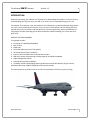
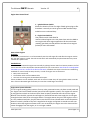
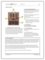
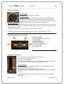
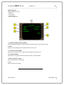
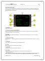
Version 1.3—February 2014 The Ul mate 757 Collec on Version 1.3 2 Disclaimer This manual is not provided from, or endorsed by the Boeing Company or any airline in any manner. This manual is not intended for real world flight. It is only for use in Microso Flight Simulator Copyright ALL elements of the QualityWings Simula ons “Ul mate 757 Collec on” are full copyright protected work. Reproduc on and/or redistribu on is STRICTLY PROHIBITED. Any excep ons are listed below. Excep ons Repaint Policy (This copyright policy is subject to change without no ce) Repain ng is allowed using the provided repaint kit but subject to the following condi ons: Modified textures may only be redistributed as freeware!! Modified textures may only be used on the QualityWings Ul mate 757 Collec on Repaints maybe distributed to 3rd party site such as Flightsim.com or Avsim.com, however they must conform to the QualityWings format as prescribed in the Users Manual! If the repaint published at the third party web site, 'QualityWings' must be listed in the author credits. End users may contact a repaint ar st directly with ques ons and/or comments. No textures whether from the repaint kit or not may be used in any other project regardless if it is commercial or freeware! Modifica on and/or distribu on of any part of the product except the repainted/modified texture files is STRICTLY PROHIBITED! All repaints (free liveries) created using the QualityWings 757 Repaint Kit remain a property of QualityWings Simula ons. www.qwsim.com qwsim.flight1.net The Ul mate 757 Collec on Version 1.3 3 INTRODUCTION www.qwsim.com qwsim.flight1.net The Ul mate 757 Collec on Version 1.3 4 INTRODUCTION Thanks for purchasing The Ul mate 757 Collec on from QualityWings Simula ons. From all of us here, at QualityWings, we hope you enjoy this add-on as much as we've enjoyed developing it for you. The Ul mate 757 Collec on is the most extensive 757 Package ever created for Microso Flight Simulator. There is truly something for everyone. Every 757 ever to come off the line from Boeing has been reproduced for your enjoyment. And with Mid-Level systems programming, we've simplified the simming experience while providing you the look and feel that makes the Boeing 757 such a special airplane to fly. PRODUCT FEATURES SUMMARY This package includes: 15 Boeing 757-200/200F/300 Models
100+ Liveries
Repaint Kit
2D Cockpit (Main panel and 7 Sub panels)
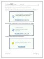
3D Virtual Cockpit (Semi Func onal)
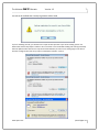
Choice of either Standard EFIS or Retrofit EFIS cockpits
Mid-Level Systems programming including Beginner and Advanced Modes.
Flight Management System
Autopilot with Autoland capability
Incredibly realis c sound package featuring Rolls Royce and Pra & Whitney Engine variants,
EICAS Aural Warnings, GPWS and Flightdeck Environment Sounds
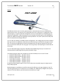
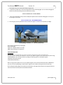
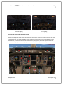
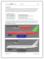
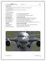
This manual outlines all product features and all of the procedures necessary to get you flying. www.qwsim.com qwsim.flight1.net The Ul mate 757 Collec on Version 1.3 5 INSTALLATION www.qwsim.com qwsim.flight1.net The Ul mate 757 Collec on Version 1.3 6 A er installing the 757 into your simulator, you will receive a series of prompts. During Ini al load a er installa on (Splash Screen), you will be informed that the installa on went OK, but the product needs to be ac vated. Ensure you have an ac ve internet connec on. Click YES A er you Click YES, you will be asked are you sure. Of course you’re sure. Click YES again. If all OK, then you will no fied of the successful Ac va on. www.qwsim.com qwsim.flight1.net The Ul mate 757 Collec on Version 1.3 7 You will the be no fied that a backup registra on will be saved If you are installing into FSX, you will then see a couple of other promots as part of FSX trus ng system. You MUST select RUN for All prompts!! Failure to do so will result in the aircra NOT loading and crashing to desktop when the QW aircra is selected. You may also be asked whether you want to trust these gauges in the future. Click YES. Clickign No will result in a prompt on subsequent Simulator sessions. www.qwsim.com qwsim.flight1.net The Ul mate 757 Collec on Version 1.3 8 QUICK START GUIDE www.qwsim.com qwsim.flight1.net The Ul mate 757 Collec on Version 1.3 9 Quick Start Guide This sec on of the manual is designed to get you flying as soon as possible. It is wri en in similar to a Frequently asked Ques ons Sec on What are these dialog popups that I get on screen a er FSX installa on? These are perfectly normal and are part of Microso ’s new so ware signature checking system. A er installing the QualityWings 757, you will see three pop-up alerts asking if you wish to run gauges that are signed by QualityWings and Virtuali. Just select ok/allow/Trust for all of them and everything will work. Where can I find the airplanes a er install? Aircra Manufacturer: Boeing-QWSim. If you are using Flight Simulator X, you must ensure that “Show All Varia ons” is checked” at the bo om of the SELECT AIRCRAFT screen in order to view installed repaints. I’ve downloaded liveries from the website but they are in a format that I don’t recognize (QWL) QWL is a format specifically designed to the read by the QualityWings Livery Manager. See more informa on about installing a livery in this manual How do I access the Virtual Cockpit? On the menu, select Views/View Mode/Virtual Cockpit. How do I perform an Engine Start Press Ctrl + E and an automa c start of both engines will commence. If you want to start manually, familiarize yourself with Start prerequisites here. How do I Perform an Autoland? Setup and prepara on for Autoland is crucial. A stable approach is necessary for the most successful autolands. Autoland is ini ated with (1) Autopilot already engaged. Start prepara on between 2500-2000 feet Ensure correct ILS Frequency and Course tuned on both the VOR/ILS Panels on the glareshield and the Aislestand. Select MCP Approach Bu on before descending through 1500 feet Engage the remaining Autopilots Localizer and GlideSlope will Arm. They will capture and engage later during the approach Ensure Autothro le engaged and speed set is correct approach speed as defined on approach page!! This is crucial to a smooth landing. At 1500 Radio Al meter, Autoland Status Annunciator will annunciate ‘LAND 3’ and EADI/PFD will show FLARE armed. The aircra will now perform the autoland. A er Touchdown, the A/T will disengage and the A/P will disengage around 80 knots. PLEASE NOTE: Rollout is NOT Simulated. You must steer the aircra a er landing!! www.qwsim.com qwsim.flight1.net The Ul mate 757 Collec on Version 1.3 10 I advance my thro les for takeoff and loud warning sound goes off? That is the takeoff configura on Warning System. This system warning you of an unsafe takeoff condion. It could be that your Parking Brakes are set, the Stabilizer is not in Green takeoff range, the spoilers are raised or your flaps are not set in a Takeoff posi on. The Upper EICAS display screen will let you know which area is not in takeoff config by displaying a Red EICAS message. For more info about the Takeoff Config Warning System, Click here. Where can I find a tutorial on loading the FMC? Click here Where can I find more informa on about the Virtual Cockpit? Click here How can I figure out how much fuel I will need for a flight? Click here www.qwsim.com qwsim.flight1.net The Ul mate 757 Collec on Version 1.3 11 How do I access 2D Panel Views? Sta c 2D Panel views are available in FS9 only and only while using Wing View models by moving your joys ck “hat” switch or by cycling through views (NUMPAD KEYS 1-8) Sta c 2D Panel views are NOT viewable in the VC models since the views you see are of the actual virtual cockpit Sta c 2D Views(Wingview Models ONLY) VC Views while in 2D Mode (VC Models ONLY) How do I access FSX Camera Views? Access FSX Views menu and Select View Mode. Camera Views are available in ‘Cockpit’ and ‘Aircra ’ Sec ons www.qwsim.com qwsim.flight1.net The Ul mate 757 Collec on Version 1.3 12 757 BACKGROUND www.qwsim.com qwsim.flight1.net The Ul mate 757 Collec on Version 1.3 13 757 BACKGROUND The Boeing 757-200/300 and Freighter aircra are members of the popular 757/767 family. They are medium sized, twin-engine short-to-medium-range jetliners known for their excep onal fuel efficiency, low noise levels, incredible opera ng performance and unmatched versa lity. That versa lity allows the aircra to fly both long and short range routes. Passenger versions of the 757 have a maximum range of 3,100 to 3,900 nau cal miles (5,900 to 7,200 km) depending on variant and sea ng configura on. Technical Features The combina on of an improved wing design and high-bypass-ra o engines make the 757 one of the most fuel-efficient aircra in the world. Both Pra & Whitney or Rolls-Royce supply engines for the 757 in thrust ra ngs from 36,600 (162.8 kilonewtons) to 43,500 pounds (193.8 kilo newtons). The 757 is unsurpassed in fuel-efficiency as it consumes up to 43 percent less fuel per seat than older tri-jets- such as the Boeing 727 which the 757 was to replace. And with the improved wing design, less engine power is required for takeoff and landing. In addi on, the 757 can reach a higher cruise al tude more quickly than many other jetliners. Flight Deck The 757 flight deck, designed for two-crew member opera on, pioneered the use of digital electronics and advanced displays. Those offer increased reliability and advanced features compared to older electro-mechanical instruments. A fully integrated flight management computer system (FMCS) provides for automa c guidance and control of the 757-200 from immediately a er takeoff to final approach and landing. The system links digital processors controlling naviga on, the Autoflight computers and Thrust Management Compu ng system to assure that the aircra flies the most efficient route and flight profile. Each Pilot has a pair of electronic displays for primary flight instrumenta on. The electronic a tude director indicator (EADI) displays the airplane a tude and autopilot guidance cues. The electronic horizontal situa on indicator (EHSI) displays a video map of naviga on aids, airports, and the planned airplane route informa on. The engine indica ng and crew aler ng system (EICAS), provides full- me monitoring of engine parameters and airplane systems. EICAS offers improved flight compartment management by: Reducing the amount of panel space required for engine instrument displays. Reducing crew workload through effec ve monitoring of engine parameters. Displaying system STATUS messages through all phases of flight. Displaying color-coded ALERT messages (Warnings, Cau ons, and Advisories) that communicate both abnormal condi ons and their urgency to the crew. www.qwsim.com qwsim.flight1.net The Ul mate 757 Collec on Variants Version 1.3 14 757-200
The defini ve version of the 757 family was launched in 1979 and entered service in 1983 wearing Eastern Airlines colors. The majority of 757s delivered were of the -200 variant. It is designed to carry 200 passengers in a typical mixed class configura on, but can accommodate up to 28 passengers in a single class configura on. While the program was a tremendous financial success, sales dwindled during the late 1990s, eventually forcing Boeing to cease produc on. The 1,050th (914 of those -200s) and last 757 was delivered to Shanghai Airlines. The 757-200 was available in two different door configura ons. One configura on used three standard doors per side with an addi onal, smaller door just a of the wing on each side for emergency evacuaons. The alternate configura on has the three standard doors per side (two towards the front and one at the a of the cabin) with two "plug-type" over-wing exits per side replacing the smaller door a of the wing. The 757-200 takeoff weights range from 220,000 pounds (99,800 kilograms) up to a maximum of 255,000 pounds (115,660 kilograms) for greater payload or range. The following engines op ons are available (or have been available) for use on the 757-200: Rolls Royce RB211-535E4 (40,200 lbs Thrust) Rolls Royce RB211-535E4B (43,500 lbs Thrust) Rolls Royce RB211-535C (37,400 lbs Thrust) Pra & Whitney PW2037 (36,600 lbs Thrust) Pra & Whitney PW2040 (40,100 lbs Thrust) Pra & Whitney PW2043 (42,600 lbs Thrust) All above men oned engine types for the 757 have 180-minute extended-range twin (engine) operaon (ETOPS) approval. Blended winglets are available as a retrofit to increase fuel efficiency and range. Winglets on the 757 have been approved for the 757-200 series as 757-200WL (757-200WingLets). Winglets offer improvements of 5% on fuel efficiency and 200 nau cal miles (370 km) on range. www.qwsim.com qwsim.flight1.net The Ul mate 757 Collec on Version 1.3 15 757-200PF
The first deriva ve of the 757 family was the 757-200 Package Freighter (PF). The PF was delivered to launch customer United Parcel Service, which ordered 20 of the variant. The 757-200PF has no passenger windows or doors and no interior ameni es. A large main-deck cargo door is installed in the forward area of the fuselage on the le -hand side. The flight crew boards the aircra through a single entry door installed immediately a of the flight deck on the le side of the aircra . This single entry door is located slightly further forward than the normal loca on of the L1 door on the passenger 757 variant. Up to 15 containers or pallets can be accommodated on the main deck of the 757PF. Total main-deck container volume is 6,600 cubic feet (187 cubic meters) and the two lower holds of the airplane provide 1,830 cubic feet (51.8 cubic meters) for bulk loading. These provide a combined maximum revenue payload capability of 87,700 pounds (39,780 kilograms) including container weight. When carrying the maximum load, the 757F has a range of about 2,900 nau cal miles (5,371 kilometers). The basic maximum takeoff weight of the PF is 250,000 pounds (113,400 kilograms), with an op on for 255,000 pounds (115,600 kilograms). The following engines op ons are available (or have been available) for use on the 757-200PF: Rolls Royce RB211-535E4 (40,200 lbs Thrust) Rolls Royce RB211-535E4B (43,500 lbs Thrust) Pra & Whitney PW2037 (36,600 lbs Thrust) Pra & Whitney PW2040 (40,100 lbs Thrust) Pra & Whitney PW2043 (42,600 lbs Thrust) www.qwsim.com qwsim.flight1.net The Ul mate 757 Collec on Version 1.3 16 757-200SF
The Boeing 757 Special Freighter (SF) did not begin it’s life as a freighter. Special Freighters started out as Passenger variants. The 757-200SF has passenger windows removed and plugged, and all but the forward 2 Entry doors are deleted or plugged. It also has no interior ameni es. There is also a SF configura on that adopts the PF design with the Le Fwd door relocated to just a of the flightdeck. A large main-deck cargo door is installed in the forward area of the fuselage on the le -hand side. Up to 15 containers or pallets can be accommodated on the main deck of the 757SF. Conversions which adapt the PF design can accommodate 15 pallets, while the non PF adapta ons can accommodate up to 14 pallets. The SF has a basic takeoff weight of 240,000 to 255,000 pounds, a range of approximately 3,000 nau cal miles, nearly 8,200 cubic feet of cargo space and a structural payload of up to 72,000 pounds. The conversion can have any of the available 757 Engine types installed. 757-200M
The 757-200M was launched for Royal Nepal Airlines. It was a conver ble version of the variant where the seats could be removed in order to place cargo on the main deck. Boeing saw this as an opportunity to showcase its 757. The 737 and 747 conver bles had proved popular and saw a market poten al for the 757-200M. However only one example was ever ordered and delivered in 1988 to Royal Nepal . www.qwsim.com qwsim.flight1.net The Ul mate 757 Collec on Version 1.3 17 757-300
The 757-300 is a stretched version of the -200. It is 23.4 (7.1 m) longer than it's smaller sister. The variant first flew in August 1998 and was delivered to Launch Customer Condor on March 10, 1999. The 757-300 has the capacity to seat 289 passengers in a typical single class configura on, though the highest configura on in airline service is 280 seats, as operated by Thomas Cook Airlines. The fuel capacity was not increased and therefore the range was reduced to 3,395 nmi (6,287 km). 55 were ordered and delivered. This model has 8 standard doors, with 4 over-the-wing exit doors, 2 on either side. It has proved popular with charter airlines for its efficiency and dense capacity. As a deriva ve, the 757-300 complements the 757-200; it is not a replacement. The 757-300 retains the simplicity and reliability of the 757-200. Both models have the same flight deck and opera ng systems, but some features have been changed. Besides a lengthened fuselage, changes on the 757-300 include new res, wheels and brakes; a tail skid; and strengthened wings and landing gear. The 757-300 maximum takeoff weight is 272,500 pounds (123,600 kilograms). It has a maximum range of 3,395 nau cal miles (6,287 km) The following engines op ons are available (or have been available) for use on the 757-200: Rolls Royce RB211-535E4B (43,500 lbs Thrust) Pra & Whitney PW2037 (36,600 lbs Thrust) Pra & Whitney PW2040 (40,100 lbs Thrust) Pra & Whitney PW2043 (42,600 lbs Thrust) All above men oned engine types for the 757 have 180-minute extended-range twin (engine) operaon (ETOPS) approval. Blended winglets are available as a retrofit to increase fuel efficiency and range. Winglets on the 757 have been approved for the 757-300 series as 757-300WL (757-200WingLets). www.qwsim.com qwsim.flight1.net The Ul mate 757 Collec on Version 1.3 18 757-200 (C32A)
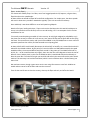
The C-32A is a military version of the Boeing 757-200 extended range aircra , selected along with the C
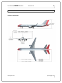
-37A to replace the aging fleet of C-137 aircra . The contract was awarded for the C-32A in August 1996. The C-32A body is iden cal to that of the Boeing 757-200, but has different interior furnishings and 21st century avionics. The C-32A provides safe, comfortable and reliable transporta on for United States leaders to loca ons around the world. The primary customers are the U.S. Vice President, using the dis nc ve call sign "Air Force Two," the first lady, and members of the Cabinet and Congress. The C-32 replaces the C-137 aircra . The passenger cabin is divided into four sec ons: The forward area has a communica ons center, galley, lavatory and 10 business class seats. The second sec on is a fully enclosed stateroom for the use of the primary passenger. It includes a changing area, private lavatory, separate entertainment system, two first-class swivel seats and a conver ble divan that seats three and folds out to a bed. The third sec on contains the conference and staff facility with eight business class seats. The rear sec on of the cabin contains general sea ng with 32 business-class seats, galley, two lavatories and closets. Because the C-32A is a high-standing aircra , it is easier to see under and around it -- an important security factor for protec ng the plane and its passengers. The C-32A is more fuel efficient and has improved capabili es over its C-137 predecessor. It can travel twice the distance on the same amount of fuel, and operate on shorter runways down to 5,000 feet (1,524 meters) in length. Its 92,000-pound (41,731 kilogram) fuel capacity allows the aircra to travel 5,500 nau cal miles unrefueled. www.qwsim.com qwsim.flight1.net The Ul mate 757 Collec on Version 1.3 19 PRODUCT PACKAGE OVERVIEW www.qwsim.com qwsim.flight1.net The Ul mate 757 Collec on Version 1.3 20 PRODUCT PACKAGE OVERVIEW EXTERIOR MODELS Choose between 15 Highly accurate and detailed models. Boeing 757-200 Passenger Rolls Royce RB211‐535E4B
Rolls Royce RB211‐535E4B w/Winglets
Rolls Royce RB211‐535C
Pra & Whitney PW2000 Series
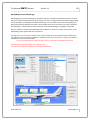
Pra & Whitney PW2000 Series w/Winglets
Boeing 757-200 Special Freighter Rolls Royce RB211‐535E4B
Rolls Royce RB211‐535C
Pra & Whitney PW2000 Series
Boeing 757-200 Package Freighter Rolls Royce RB211‐535E4B
Pra & Whitney PW2000 Series
Boeing 757-200 Air Force Variant (C-32A) Pra & Whitney PW2000 Series w/Winglets
Boeing 757-300 Passenger Rolls Royce RB211‐535E4B
Rolls Royce RB211‐535E4B w/Winglets
Pra & Whitney PW2000 Series
Pra & Whitney PW2000 Series w/Winglets
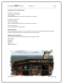
There are over 100 Custom anima ons on the exterior models including, but not limited to: Shock Strut Compression with realis c animated bogey lt behaviour
All Flight Controls
Detailed Thrust Reversers with Blocker Door anima ons
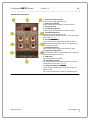
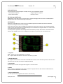
Landing gear w/Nose wheel steering
Passenger Doors with correct anima on
Cargo doors
Freighter Door (Freighter models)
Tailskid (‐300)
Realis c Wing Flex (Xml)
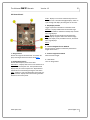
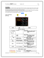
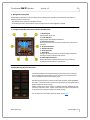
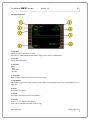
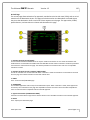
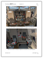
And Much, much more…. www.qwsim.com qwsim.flight1.net The Ul mate 757 Collec on Version 1.3 21 LIVERIES Choose from over 125 High Quality real-world liveries for free from the QualityWings painters. We've even included every 757 livery ever produced for some airlines. Introduced in SP2 are QualityWings High Defini on Textures (QWHDT) for the FSX Version of the product. REPAINT KIT We've provided a detailed paintkit for those who would like to paint their own liveries. There are many effects included to ensure that ANYONE can make great looking paints! It also includes MANY op on layer sets allowing you to match several different airline configura ons. www.qwsim.com qwsim.flight1.net The Ul mate 757 Collec on Version 1.3 22 FLIGHTDECK Both 2D and 3D (Virtual Cockpits) flightdecks are provided. Standard and Retrofit flightdecks are available. Standard includes the tradi onal EADI and EHSI and the Retrofit includes the LCD upgrade which is now available for the 757 aircra . Widescreen 2D Panels are also available and are selected by default. The 2D Flightdeck also has the following panels: Main Instrument Panel (Captains View ONLY)
Overhead Panel
Radio Stack
Forward Aisle Stand/Control Stand
FMC CDU
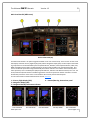
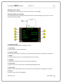
EFIS Control Panel
Aileron/Rudder Trim Panel
Ligh ng Panel
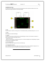
Landing View Panel www.qwsim.com qwsim.flight1.net The Ul mate 757 Collec on Version 1.3 23 All 2D panel func onality is available in the 3D Virtual Cockpit. More in-depth informa on about the 2D main panels and the 3D virtual cockpit can be found later in this manual. FLIGHT MANAGEMENT SYSTEM The FMS interacts and directs the autopilot to provide route Lateral and Ver cal naviga on (LNAV/VNAV). LNAV mode directs the Autopilot to fly the FMC flight plan route automa cally and VNAV mode directs the Autopilot to meet the FMC climb, cruise, and descent targets and restric ons. Users can use the FMC to manually create flight plans, load stored flight plans or import the current ac ve ATC/GPS flight plan created or loaded via the Flight Planning page of FS9/FSX. The FMC can also modify the ac ve flight plan route while en route and insert stored routes such as SID/STAR's and En-route Airways. SYSTEMS PROGRAMMING The real-life 757 aircra is a very complex aircra . There is a high level of automa on in the systems, but here at QualityWings—we’ve Simplified things for YOU to allow for a more efficient Flight Simming experience. Those familiar with the real 757 aircra will be able to appreciate some of the characteriscs of the 757 aircra that we’ve included while those who are not familiar with the aircra will not be overwhelmed by a Full level simula on. Also, QualityWings Op ons allows for even further simplificaon for those simmers who really just want to “Get in and fly”. Many systems simulated (Hydraulics, Electrical & Fuel Systems just to name a couple) and there is some limited interac on with others (Bleed system as an example). But, this is NOT a procedures type of simula on. The systems are designed for normal opera on ONLY. Engine fires, in-flight emergencies and the effects on systems due to abnormal configura ons are NOT simulated. Complexity, Simplified! www.qwsim.com qwsim.flight1.net The Ul mate 757 Collec on Version 1.3 24 SOUNDS High Quality soundsets are provided for both Pra & Whitney and Rolls Royce Engine variants. We believe they are THE most realis c rendi ons of the powerplants ever available for the Microso Flight Simulator series. The exterior engine sounds were recorded in the vicinity of the powerplants during an engine run through the COMPLETE thro le range (Startup to Idle to Takeoff to Shutdown). Interior engine sounds were recorded on board during the same engine runs. In addi on to the engines, the soundest includes a carefully constructed mixture of flightdeck & cabin environment sounds. Hear the sound of the equipment cooling systems and the air condi oning pack noise of the Nose Landing gear being deployed and retracted. Spoiler rumble and Auto-speedbrake lever sounds are also simulated. Other sounds, you’ll have to discover on your own! Ground Proximity Warning System sounds warn you of the aircra s proximity to the ground. From Al tude callouts to bank angle awareness, we’ve got you covered. QualityWings op ons allows you to adjust some of the callouts to give you more control of what callouts you want to hear. Level A Warning and Level B Cau on sounds generated by the EICAS and WEU systems are also provided. The QualityWings Pre-Recorded Announcement System (QWPAS) promises to take your flight experience to another level by including of several commonly heard Announcements from Flight A endants and Flightdeck crew. Takeoff Callouts, landing checklists, it’s all there! FLIGHT DYNAMICS MODEL You can’t see it, but you sure can feel it.. Based on input from real-life 757 pilots and simulator experience - the flight dynamics promise to give you an authen c 757 experience! OPTIONS There are many op ons for you to choose from with the QualityWings 757. Many of them can be controlled on the fly via the QualityWings Control Panel. The panel is available via a SimIcon and also on the FS9 views menu. In addi on to the control panel, many more op ons can be set via a configura on file conveniently located in the QualityWings folder. In total there are more than 50 different op ons to choose from. LIVERY MANAGER The QualityWings Livery Manager allows for EASY installa on of repaints payload adjustments and the ability to set cockpit panel view op ons to fit your Monitor aspect ra o. www.qwsim.com qwsim.flight1.net The Ul mate 757 Collec on Version 1.3 25 FLIGHT MANUAL www.qwsim.com qwsim.flight1.net The Ul mate 757 Collec on Version 1.3 26 INTRODUCTION General The purpose of this manual is to provide QualityWings 757 pilots with a document which serves as a training aid to become familiar with the QualityWings 757 This sec on of the manual provides general aircra informa on and for all of the flightdeck panels which allow you to interface with the aircra and it’s systems. Each relevant panel is described in detail and a general descripon of the system is also provided. Informa on on Exterior features such as flight controls and doors is also provided. The following areas are covered: Aircra General Principal Dimensions
Flight Controls
Doors
Exterior Lights
Overhead Panel IRS Panel (Iner al Reference System)
Yaw Damper Panel (Yaw Damper System)
Hydraulic Control Panel (Hydraulic System)
Misc Annunciator Panel (Door Warning System/Ice Protec on System)
Electrical Control Panel (Electrical System)
APU Control Panel (APU System)
Engine Start Control Panel (Engine Start System)
Fuel Control/Quan ty Panels (Fuel System)
Passenger Signs Control Panel
Air Systems Control Panel (Air Condi oning/Pneuma cs Systems)
Control Quadrant Thrust Levers/Reverse Thrust Levers
Fuel Cutoff Switches
Flap Lever
Spoiler Lever
Stab Trim Control Switches/Indica on
FMCS Control Display Unit
EFIS Control Panel
EICAS Display Select Panel
www.qwsim.com qwsim.flight1.net The Ul mate 757 Collec on Version 1.3 27 Communica ons Cluster VHF Communica on Panels
ATC Control Panel
ADF Control Panel
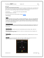
Main Instrument Panel (Standard) Mach/Airspeed Indicator
Al meter
Standby A tude Indicator
Standby Airspeed Indicator
Standby Al meter
Electronic A tude Director Indicator
Electronic Horizontal Situa on Indicator
Standby Engine Indicator
EICAS Displays (Upper and Lower)
Flap Posi on Indicator
Landing Gear Control Lever
Autoflight Control System MCP
Naviga on Control Panel
Main Instrument Panel (Retro-Fit) Primary Flight Display (LCD)
Naviga on Display (LCD)
Standby Engine Indicator
EICAS Displays (Upper and Lower)
Flap Posi on Indicator
Landing Gear Control Lever
Autoflight Control System MCP
Naviga on Control Panel
Standalone EFIS Control Panel (Standard and Retro-Fit) FMCS CDU
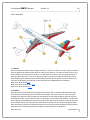
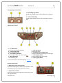
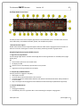
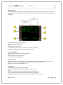
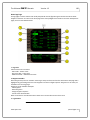
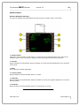
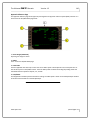
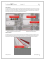
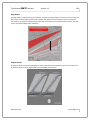
www.qwsim.com qwsim.flight1.net The Ul mate 757 Collec on Version 1.3 28 OPERATING LIMITATIONS / PARAMETERS Limita ons 1. Opera onal Envelope A. Max opera ng pressure al tude: 757-200 42,000 . 757-300 42,000 . B. Max takeoff/landing pressure al tude: 757-200 9,500 . 757-300 9,500 . 2. Maximum Airspeed Limita ons: • VMO - indicated by max airspeed pointer on airspeed indicator. • MMO - 0.86 M • Maximum Gear Opera ng/Extended Speed: 270/.82M Maximum Alternate Gear Extension Speed: 250/.75M • Turbulent air speed: 290 knots/.78M • Flap Placard Speeds: 3. 757-300: Flaps 1 takeoffs are prohibited. Parameters 1. Crosswind Guidelines • Max Recommended Takeoff Crosswind: 40 Knots • Max Recommended Landing Crosswind Component Guidelines (Not Autoland): 40 Knots www.qwsim.com qwsim.flight1.net The Ul mate 757 Collec on Version 1.3 29 GROSS WEIGHT LIMITATIONS Maximum Design Taxi Weight (MTW). Maximum weight for ground maneuver as limited by aircra strength and airworthiness requirements. (It includes weight of taxi fuel.) Maximum Design Takeoff Weight (MTOW). Maximum weight for takeoff as limited by aircra strength and airworthiness requirements. (This is the maximum weight at start of the takeoff run.) Maximum Design Landing Weight (MLW). Maximum weight for landing as limited by aircra strength and airworthiness requirements. Opera ng Empty Weight (OEW). Weight of structure, powerplant, furnishing systems, unusable fuel and other unusable propulsion agents, and other items of equipment that are considered an integral part of a par cular airplane configura on. Also included are certain standard items, personnel, equipment, and supplies necessary for full opera ons, excluding usable fuel and payload. Maximum Design Zero Fuel Weight (MZFW). Maximum weight allowed before usable fuel and other specified usable agents must be loaded in defined secons of the aircra as limited by strength and airworthiness requirements. Maximum Pay load. Maximum design zero fuel weight minus opera onal empty weight. Payload is passengers and cargo on the Passenger variants and Total freight on the Freighter models. SYSTEMS LIMITATIONS AUTOFLIGHT Limita ons 1. On takeoff, do not engage autopilot below 1,000 feet AGL 2. Max allowable winds for autoland: Headwind - 25 knots Tailwind - 15 knots 757-300: Tailwind - 12 knots (Flap 30) 757-300: Tailwind - 15 knots (Flap 25) Crosswind - 25 knots (15 knots when RVR is 2400 or less) 3. Autopilot use prohibited below 100’ RA at airport pressure al tudes above 8,000 feet. www.qwsim.com qwsim.flight1.net The Ul mate 757 Collec on Version 1.3 30 AIRCRAFT GENERAL PRINCIPAL DIMENSIONS www.qwsim.com qwsim.flight1.net The Ul mate 757 Collec on Version 1.3 31 FLIGHT CONTROLS 1 – Ailerons Ailerons control the airplanes ROLL along the Roll Axis. There is one aileron on each wing. The ailerons move in opposite direc ons of each other to make the aircra turn. For instance, when you turn your control wheel to the le to start a le turn – the le aileron will raise to “dip” the wing into the turn while the right aileron will “raise” the right wing. Ailerons can be controlled manually by the pilot or automa cally by the Autopilot and are hydraulically powered. Aileron posi on can be monitored on the Lower EICAS display. Aircra Roll can be monitored on the A tude Director Indicator. Read more about EICAS here. Read more about the Autopilot here. Read more about the ADI here. 2 – Elevators Elevators control the airplanes PITCH along the Lateral Axis. Pitch is the Nose and Nose Down movement of the aircra also referred to as the aircra s a tude. The elevators are for short term pitch changes while long-term pitch changes are controlled by the Horizontal Stabilizer (more on the Horizontal Stabilizer later in this sec on). There is one Elevator on each Horizontal Stabilizer. The elevators move together UP and DOWN to make the aircra climb or descend. For instance, when you push the control column forward, the elevators will move down and make the nose of the aircra pitch downward. Pulling the column back causes the elevators to move Up and the aircra nose to pitch upward. Elevators can be controlled manually by the pilot or automa cally by the Autopilot .
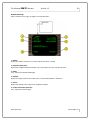
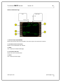
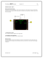
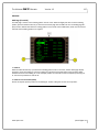
www.qwsim.com qwsim.flight1.net The Ul mate 757 Collec on Version 1.3 32 They are hydraulically powered. Elevator posi on can be monitored on the Lower EICAS display. Aircra A tude can be monitored on the A tude Director Indicator. Read more about EICAS here. Read more about the Autopilot here. Read more about the ADI here. 3 – Rudder A single Hydraulically powered Rudder controls the airplanes YAW along the Ver cal Axis. Yaw is the Side to side movement of the aircra . The rudder is located on the Ver cal Stabilizer. The rudder moves side to side and is controlled by the Rudder pedals. For instance, pushing the le rudder pedal forward will move the rudder to the le causing the nose to turn towards the le . Keep in mind that rudder movements will induce rolls, so in the previous le turn example the plane would start to roll to the le . This is because the right wing speeds up just a bit and this causes more li on that wing. The Rudder can be controlled manually by the pilot and automa cally by the Autopilot and Yaw Damper systems. Elevator posi on can be monitored on the Lower EICAS display. Read more about EICAS here. Read more about the Autopilot here. Read more about the Yaw Damper here. 4 – Horizontal Stabilizer The Horizontal Stabilizer (Le and right are one piece) controls Long Term pitch changes along the Lateral Axis. The horizontal stabilizer pivots on the airplane structure at the rear spar and is hydraulically powered. Trim commands are ini ated on the control wheel (not simulated in this package) or on the Control Quadrant. Trim Nose up commands move the en re stabilizer with the Leading edge going down. Trim Nose Down commands move the en re stabilizer with the Leading edge going up. Automa c trim commands are also generated by the Autopilot. Stabilizer posi on can be monitored on the Stab Trim posi on indicator located on the Control Quadrant. Read more about the Autopilot here. Read more about the Stabilizer Trim Posi on indicators here. 5 – Spoilers/Speedbrakes 12 (6-each wing) Hydraulically powered Spoilers help augment ailerons for ROLL control and also funcon as Speedbrakes to help slow the plane down in-flight. The speedbrakes are also deployed automa cally during Rejected takeoffs and Normal landings to help ensure all aircra weight is on the Main wheels to aid in braking. They are numbered from 1-12 from le wing to right wing. Spoilers 4 and 9 are electronically locked out in-flight and only serve as ground spoilers. For Roll control, the spoiler deployment “mixes” with the ailerons to help the aircra turn. The spoilers move AFTER the ailerons. For in-flight speedbrakes, the spoilers may be deployed to help slow the aircra down. During takeoff, the spoilers deploy as Autospeedbrakes if a rejected takeoff is sensed. During landing, the autospeedbrakes deploy automa cally when armed prior to touchdown. Read more about the Spoiler Lever here. www.qwsim.com qwsim.flight1.net The Ul mate 757 Collec on Version 1.3 33 6 – Trailing Edge Flaps 7 – Leading Edge Slats The Trailing Flaps and Leading Edge Slats work together to form the High Li Control System. The flaps/
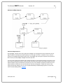
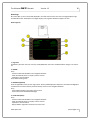
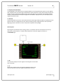
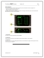
slats change the aerodynamic configura on of the airplane to improve performance during a par cular flight condi on. Takeoff and landing characteris cs are improved, and greater maneuverability is provided to meet departure and arrival airspeed, climb and descent requirements. The trailing edge flap system consist of four double-slo ed trailing edge flap control surfaces that extend from the trailing edge of the wing. There are 10 leading edge slats: One inboard and four outboard slats are a ached to the leading edge structure of each wing. The slats are numbered 1 to 10, from outboard le wing to outboard right wing. The Flap lever controls the en re High Li system with the Slats/Flaps systems working together in a predetermined sequence. The system is normally powered by hydraulics with an electric backup (not simulated). The Trailing Edge Flaps have seven posi ons: UP – 1 – 5 – 15 – 20 – 25 – 30. The slats have three posions. Up – Takeoff and Landing. In the takeoff posi on they remain sealed with the wing. In the landing posi on the slats separate (gap) from the wing. Autoslat System There is an Autoslat system that automa cally extends the Slats from the sealed posi on to gapped in the event of a Stall. The Flap Load relief system retracts the Trailing edge flaps from 30 units to 25 if airspeed exceeds 170 knots. When the speed drops below 165 knots, the flaps return to the 30 unit posi on. Load relief is ONLY for Flaps 30. Read more about the Flap lever here. Read more about the Flap Posi on Indicator here. DOORS Doors can be controlled using Standard Flightsim key combos or via the QualityWings Control Panel. More informa on on the QualityWings Control Panel can be found here. Passenger Variants The 757‐200 has 6 Main Entry/Service Doors (3 each side) and the number of emergency exits depends on aircra configura on. Some configura ons have 4 small overwing exit doors (2 each side) and others have 2 mid sized exit doors (1 each side) just a of the wings. The 757‐300 has 6 Main Entry/Service Doors (3 each side) and 6 Emergency exits. It has both the overwing and a wing exits that can be found on the -200 series. Two cargo doors are available for loose baggage and loose/small freight. The forward and a cargo doors are on the right side of the aircra below the aircra water line. There is a Bulk cargo door opon that was available on some 757s are airline request. This door is shown on SOME airlines, but is not simulated on the QualityWings 757. Only the Main Entry/Service Doors and Cargo Doors are simulated on the QualityWings 757. www.qwsim.com qwsim.flight1.net The Ul mate 757 Collec on Version 1.3 34 Passenger Variant Door 1 – L1 Main Entry Door 2 – L2 Main Entry Door 3 – L4 Galley/Service Door 4 – R4 Service Door 5 – R2 Service Door 6 – R1 Galley/Service Door 7 – A Cargo Door 8 – Fwd Cargo Door www.qwsim.com SHIFT + E SHIFT + E + 2 SHIFT + E + 4 SHIFT + E + 4 SHIFT + E + 4 SHIFT + E + 4 SHIFT + E + 3 SHIFT + E + 3 qwsim.flight1.net The Ul mate 757 Collec on Version 1.3 35 Freighter Variants The 757-200 Special Freighters have all but the forward Entry doors deleted. Other door outlines may be visible, but these doors do not open. The 757-200 Package Freighter only has the 2 Fwd Entry Service doors. A Large Cargo door is located on the le side of the aircra a of the le Fwd Entry door. It has 2 open posi ons: Canopy (Half-open) and Full Open. Annunciator Lights on the Overhead panel and EICAS messages on the Pilots Main panel give door indica ons. Read more about the Misc Annunciator Panel (Door Warning Indica on lights) on the Overhead here. Read more about the Door Warning EICAS here LIGHTING SYSTEMS Exterior Ligh ng and flightdeck ligh ng systems are simulated in the QualityWings 757. Exterior Ligh ng Exterior ligh ng consists of these lights: · landing · runway turnoff · an -collision · naviga on (posi on) · wing leading edge illumina on · taxi · logo www.qwsim.com qwsim.flight1.net The Ul mate 757 Collec on Version 1.3 Boeing 757-200 Shown (B757-300 Similar) 36 1 ‐ Landing Lights The landing lights consist of the le , right, and nose gear landing lights. The le and right landing lights are located in the le and right wing root and two landing lights are on the nose landing gear. 2 ‐ Taxi Light One taxi light is installed on the steerable por on of the nose landing gear. 3 ‐ Runway Turnoff Lights Two runway turnoff lights are located on the upper por on of the nose landing gear strut. 4 ‐ An –Collision Lights The white an –collision lights are strobe lights located on each wing p. On aircra with winglets, lights located near the top outboard p of the Winglets. The red an –collision lights are strobe lights located on the top and bo om of the fuselage. 5 ‐ Wing Illumina on Lights Wing lights are installed on the fuselage and illuminate the leading edge of the wing. 6 ‐ Naviga on Lights The naviga on lights are standard red (le forward wing p), green (right forward wing p), and white (a p of both wings) posi on lights. www.qwsim.com qwsim.flight1.net The Ul mate 757 Collec on Version 1.3 37 7 ‐ Logo Lights Logo lights are located on the stabilizer to illuminate the logo on the ver cal tail surface. Flight Deck Ligh ng Flight deck ligh ng is provided for panel illumina on There are 2 stages of ligh ng in the Virtual cockpit and 2 Stage in the 2d Cockpit. In both cockpits, the Light Override (LT OVRD) switch is used to control panel ligh ng. Read more about the Light Control Panels here. www.qwsim.com qwsim.flight1.net The Ul mate 757 Collec on Version 1.3 38 OVERHEAD PANEL 1 – IRS Mode Select Panel 2 – Yaw Damper Panel 3 – Hydraulic Control Panel 4 – Miscellaneous Annunciator Panel 5 – Electrical Power Control Panel 6 – APU Control Panel 7 – Engine Start Control Panel 8 – Fuel System Panels (Control & Quan ty) 9 – Passenger Signs Control Panel 10 – Air Condi oning and Bleed Air Control Panels 11—Ligh ng Control Panel 12—Emergency Lights Control Panel 13—An -Ice Control Panel www.qwsim.com qwsim.flight1.net The Ul mate 757 Collec on Version 1.3 39 IRS Model Select Panel 1 – IRS ALIGN/ON DC Lights The ALIGN light turns on steady a er turning on the IRUs for the ini al alignment. The light exnguishes a er IRS system is fully aligned. The ON DC light turns on momentarily during the ini al IRS alignment 2 – IRS Mode Display Window Displays Aircra present posi on when IRS system is aligned. 3 – IRS Mode Select Switches Allows the IRS system to be turned on. Click all 3 switches from OFF to the NAV posi on and a er a short wait for alignment, the system will be up and running in Naviga on mode. IRS is aligned by default. NOTE: No other steps are required for IRS alignment other than turning the switches to NAV. Iner al Reference System Refresher An Iner al Reference system is standard equipment on the 757. The Iner al Reference System is controlled by the IRS Mode Control Panel on the overhead panel. When opera ng in the naviga on mode, the IRS provides a tude to the EADI or PFD and heading informa on to the EHSI or ND. An IRS must be aligned before it can enter the NAV mode. Rota ng the IRS mode selector from OFF to NAV begins the IRS alignment. The IRS performs a short power test, during which the ON DC light illuminates. When the ON DC light ex nguishes the ALIGN light illuminates. Alignment requires approximately ten seconds, as we have speed up this process to get you flying quicker. It is NOT NECESSARY to enter Present posi on on the FMCS CDU to complete the alignment. Alignment can be accomplished only when the airplane is not moving. Alignment stops if an IRU detects mo on during alignment. When the mo on stops, the alignment con nues automa cally. The IRS is aligned when all IRUs enter the naviga on mode. Alignment is lost if the selector is moved out of the NAV posi on. www.qwsim.com qwsim.flight1.net The Ul mate 757 Collec on Version 1.3 40 Yaw Damper Control Panel 1 – Yaw Damper Engage Switches The Yaw Damper switches control the engagement of the Yaw Damper System. The switches work in unison, meaning that clicking on one operates both switches. Click to turn the Yaw Damper On and OFF The ON annuncia on indicates that the system is func onal. Click the switches to turn off the Yaw Damper and the ON annuncia on will disappear. The INOP annuncia on shows when the Yaw Damper system is switched off, or when the switch is ON and the Iner al Reference system is not opera ng. When the INOP annuncia on is present, the EICAS system generates Yaw Damper EICAS messages shown on the Upper EICAS display: L (R) YAW DAMPER Please Note that the ON annuncia on DOES NOT tell Flight Simulator Yaw Damper status. The INOP lights are a only a light simula on of what happens in the real 757 aircra . We have disabled the use of Flight Simulator Yaw Damper on the QualityWings aircra . Yaw Damper System Refresher An inherent characteris c of all swept back wing airplanes is a yawing mo on that induces sideslip and roll. The yaw damper systems improve turn coordina on and dutchroll damping. www.qwsim.com qwsim.flight1.net The Ul mate 757 Collec on Version 1.3 41 Hydraulic Control Panel 1 – Le System Pump Switches Allows for control of the Le Engine Driven hydraulic Pump and the Le Electric Driven Hydraulic Pump. A PRESS light indicates that the respec ve pump has low output pressure. This can be because the switch is OFF or in the case of the Engine pump, it Illuminates when the le engine is shutdown since the engine drives this pump. 2 – Center System Pump Switches Allows for control of the two Electric Driven Hydraulic Pumps for the Center system. A PRESS light indicates that the respec ve pump has low output pressure. This can be because the switch is OFF or the aircra is in a Load Shed condi on. Both engines are required to be running for the C2 Electric Pump to operate. 3 – Right System Pump Switches Opera on similar to the Le System Pump Switches Hydraulic System Refresher The 757 is equipped with 3 hydraulic systems labeled the Le , Center and Right systems. The hydraulic system provides the power to operate systems such as the landing gear and all flight controls. There are 2 pumps available for each system for a total of 6 in the system. The le and right systems each have (1) Engine driven hydraulic pump and (1) Electric Hydraulic Pump. When the engines are not running, the pumps do not output any pressure. When the engines are running, the pumps provide approximately 3000 psi pressure as long as their respec ve switches remain in the ON posi on. The Electric hydraulic pumps operate as long as their switches are on and are available as long as the aircra has AC power available. The Center system is equipped with 2 Electric hydraulic pumps that operate similar to the Le and Right system Electric pumps. The Center pumps are however subject to Load Shedding when the engines are not running. To prevent excessive electrical loads while using External electrical power or APU electrical power, only (1) center hydraulic pumps is available at a me. If both switches are on, then only the C-1 hydraulic pump operates. On the QualityWings 757, hydraulic pressure is necessary for opera on and the anima on of the Flight Controls. The Ram Air Turbine is NOT simulated. If your hydraulics are not on, you will not be able to control the ailerons, rudder, elevator or the horizontal Stabilizer. Therefore direc onal control will be compromised as hydraulics are necessary for flight! www.qwsim.com qwsim.flight1.net The Ul mate 757 Collec on Version 1.3 42 Miscellaneous Annunciator Panel 1 – ENTRY DOORS light One or more Entry doors are open. Associated EICAS messages also show 2 – CARGO DOORS light One or both Cargo Doors are open. Associated EICAS messages also show 3 – Probe Heat system lights All probe Heat lights illuminate when the engines are shutdown. Ex nguished when engines running. Door Warning System Refresher The door warning system alerts the flightcrew of a door that is open. The system alerts the crew via the Miscellaneous Annunciator panel AND via the EICAS system in the forum of level C Advisory messages. EICAS messages for the doors are shown in Fig. 102 just to the le , but only represent the door nomenclature Not all EICAS messages are shown. If any of the Le side entry/service doors are opened, the EICAS message L ENTRY DOORS shows. R ENTRY DOORS shows for any right side service doors. CARGO DOORS shows when the cargo doors are opened (Cargo doors cannot be opened individually) They door key commands can be found here. More informa on on the QualityWings control panel can be found here.
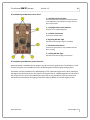
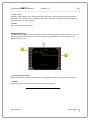
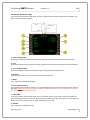
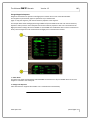
Probe Heat System Refresher The various Air Data probes/sensors on the 757 are electrically heated to ensure ice does not accumulate. Ice accumula on can prevent reliable data from these sensors which is a safety hazard. The probe heat system is automa cally controlled on 757s. There is no manual control of probe heat. On engine start, all probes are turned on. They shutoff on engine shutdown. www.qwsim.com qwsim.flight1.net The Ul mate 757 Collec on Version 1.3 43 Electrical System Control Panel 1 – Main Ba ery Switch Right Click to li the cover, then Ba ery switch selec on is available. Normal posi on for the Main ba ery switch is ON. When switch ON, the OFF light is ex nguished. 2 – Standby Power Switch and Standby power Sta‐
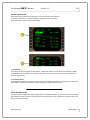
tus light Turns Standby Power ON or Off. Standby Power Off light illuminates when standby power is off. Real-life standby system dependencies are not simulated. 3 – External Power Switch External power becomes available automa cally when the aircra is on the ground, engines are shutdown and the parking brake is set. AVAIL means available. Push switch to turn on electrical power. ON means external power is powering the electrical system. 4—U lity Bus Switches Allows selec on of the Le or Right U lity busses. 5– Le and Right Generator Control Switches Controls engine generators. The switches are normally le ON to allow the respec ve engine generator to come online and power the busses a er engine start. The OFF light illuminates when engines not running. OFF light ex nguishes when engines running (switch in ON posi on. Any one generator can completely power the aircra Electrical Power System Refresher The 757 Electrical Power system is very complex. It consists on an AC (Alterna ng Current) system, a DC (Direct Current) system and a Standby system. The AC system consists of (3) powerplant (Engine and APU) driven generators and external power. The DC and Standby systems consists of many components - but is not at all discussed here. The Ba ery is the only DC power system component controlled in this simula on. The QualityWings 757 simulates External power, APU generator power and Engine generator power. On the ground, when the engines are shutdown and the parking brake is set….External power will become available for use. When the APU is running, APU electrics is available. When the engines are running, the engines will power the electrical power system so long as their switches are on. You will need to start your APU prior to engine shutdown if you do not want to lose power. www.qwsim.com qwsim.flight1.net The Ul mate 757 Collec on Version 1.3 44 APU Control Panel 1 – RUN light Flashes twice during start of APU, simula ng the APU Electronics unit prestart internal tes ng. Remains on steady once APU is up and running. 2 – FAULT light Flashes once during APU start and shutdown to simulate the APU fuel valve transi on to open (during start) and close (during shutdown). 3 – APU Master Switch Three posi on switch (OFF-ON-START). Only one click required to start/shutdown APU. How to Start/Shutdown APU When the APU is off, the switch is in the OFF posi on. Click Once to turn on. The switch will automa cally run through the ON posi on to START and then spring back to ON. The FAULT light flashes once, followed by 2 flashes of the Run light. A er a sped up simula on of the APU spool-up me (10 seconds instead of the real-life 40-60 seconds) then RUN light turns on steady to simulate APU running. To shutdown APU, click switch once, and it moves to OFF. The RUN light ex nguishes and the FAULT light flashes twice. The APU door (Fig. 1) on the exterior model is mounted on the fuselage just above the right horizontal stabilizer. It opens and closes in response to APU modes. It is open during APU opera on and closed (faired with fuselage) when APU is off. Fig. 1 ‐ APU Door shown in the open posi on APU System Refresher The 757 is equipped with a single Allied Signal model 331-200 Auxiliary Power Unit (APU) installed in the a tailcone of the aircra . The APU is an engine that is capable of supplying electrical power and Pneuma cs. The pneuma cs are normally al tude limited, but on the QualityWings 757 Pneuma cs and Electrical power are always available regardless of al tude. www.qwsim.com qwsim.flight1.net The Ul mate 757 Collec on Version 1.3 45 Engine Start Control Panel 1 ‐ Igni on Selector Switch Allows for selec on of One of a single of both Ignitor plugs to fire. Procedure is normally to use #1 Ignitor on Odd numbered days and #2 on even numbered days. 2 – Engine Start Switches Two posi on switch: GND & AUTO Used to ini ated engine start. User places Start switch to GND to start engine and when engine approaches idle the switch automa cally goes back to AUTO posi on. See How to Start engines (below) for more informa on. How to Start Engines AutoStart FS default Key command Ctrl + E will automa cally start the Le engine first and a er that engine reaches idle, the right engine is started. The Fuel Control switch will automa cally be placed to RUN at the precise moment for a perfect start. Standard Start The user can also ini ate the engine start manually by placing the Start Switch to the Auto posi on. The fuel control switches will also be placed to the Run posi on for you at max motor. New for SP3 is a Config op on that allows you to be in control of the fuel control switch. Standard start requires that the Air Condi oning and Bleed Air Control Panel be setup correctly. In order for engine start to commence: Both packs must be off, The Isola on Valve must be OPEN and the APU must be running with the APU Bleed Valve Open. If these condi ons are not sa sfied, switch will not remain in GND. They will spring back to Auto 2 seconds later. If the on-side VALVE light illuminates, the start has started begun successfully. Engine Start System Refresher The 757 engine star ng system consists of a start valve, pneuma c starter, the Start control panel and the Engine Fuel Control Cutoff switches (part of the Fuel & Igni on systems). The engines are started by using the Start switch on the Start Control Panel to open a pneuma c start valve on the engine. Bleed air from the APU, opposite aircra engine or Ground Pneuma cs carts supply the air that goes through the Start Valve to turn the engine Starter. The engine starter then turns the engine to suck in air. At a predetermined point, the pilot then moves the Fuel Control Cutoff switch to the Idle posi on. When the switch is placed to idle, fuel is supplied to the engine and igni on is started to create combus on to allow the engine accelerate to idle. At or around idle, the engine start valve closes and the starter disengages from the engine, as it is no longer needed.
www.qwsim.com qwsim.flight1.net The Ul mate 757 Collec on Version 1.3 46 Fuel Systems Panels 1 – Le (Right) Main Tank Fuel Pump Switches Allows for selec on of the fuel pumps. The PRESS lights indicate that fuel pump has no output pressure. PRESS light will illuminate if respec ve tank is empty of the switch is OFF. Autorun of Le system fuel pump during APU ops not simulated. Engine opera on not affected by pumps off. Engines will suc on feed. 2 – Center Tank Fuel Pump Switches Switches are selectable ON /OFF. Pumps must be ON in order to burn fuel from the center tank. The PRESS light on the switch indicates that the pump has no output pressure Center Tank Pump output pressure light will illuminate for any of the following: • The switch is OFF • The switch is ON with no fuel in the center fuel tank If the Center tank switches are ON with the respec ve side engine OFF. The center tank pumps will only operate when the respec ve side engine is running. 3 – Fuel CONFIG light Illuminates for either of the following: • Total Fuel Quan ty less than 2,200 lbs 4 – Fuel Quan ty Display Displays the fuel quan ty of each tank and Total Fuel Quan ty. 5—Fuel Crossfeed Switches Allows for selec on of Fuel Crossfeeding. To crossfeed, open either crossfeed valve and turn off the fuel pumps for the tank OPPOSITE of the tank you want to burn from. Fuel Systems Refresher The 757 is equipped with 3 Fuel tanks: Le and Right Main tanks which are located in each respec ve wing and a Center Tank located in the center wing box. The Fuel capacity of the Wing tanks are 2236 gallons (14,980 lbs) and the Center Tank capacity for all versions except the C32-A is 7017 (47,013 lbs). The C32-A has an addi onal 2298 gallons (15,400 lbs ) available in the Center Tank for a total fuel Quan ty of 92,000lbs instead of the normal 76,000 lbs. There are a total of 6 Fuel Pumps in the Fuel system: (2) for each Main tank and (2) for the Center Tank. The Center tank pumps are called Override Fuel Boost Pumps and operate at a higher output pressure than the Main Tanks boost pumps. Because of this, the center tank fuel quan ty is used first. Once the center tank is depleted, then main tank fuel is used. The Fuel Crossfeed valves allow the engines to use either fuel tank f necessary. www.qwsim.com qwsim.flight1.net The Ul mate 757 Collec on Version 1.3 47 Passenger Signs Control Panel 1 ‐No Smoking Sign Switch Sounds No Smoking Chime. AUTO posi on has no func on. 2 – Fasten Seatbelt Sign Sounds Fasten Seatbelt Chime. AUTO posi on has no funcon. Ligh ng Control Panel 1 – LT OVRD Switch Controls 2D Panel ligh ng (ON/OFF) 2 – Posi on Light Switch Controls posi on ligh ng 3 – An ‐collision Light Switch Controls Upper Lower An -collision lights 4 – Wing Light Switch Controls Wing Lights 5 – Logo Light Switch Controls Logo Lights 6 – Taxi/Runway Turnoff Light Switch Controls Taxi/Runway Turnoff lights on nose gear 7 – Landing Lights (WING) Controls Landing Lights on the wings 8 – Landing Lights (NOSE) For more informa on on the exterior ligh ng, click here. An ‐Ice Control panel 1—Wing An ‐Ice Switch and Valve lights Switch Controls Wing An -Ice which is only available on the air. Valve light remains on if WTAI is selected on the gnd. 2—Engine An ‐Ice Switches Switch Controls selec on of Engine An -Ice which is only availwith engines running. www.qwsim.com qwsim.flight1.net The Ul mate 757 Collec on Version 1.3 48 Air Condi oning and Bleed Air Control Panel 1 – Le (Right) Pack OFF Lights Illuminate when the respec ve pack switch is placed to the Off posi on. Must be OFF for engine start via start control panels. 2 – Le (Right) Pack Control Switches Controls the air condi oning packs. 3 – Isola on Valve Switch Controls the Isola on Valve 4 – Right Eng BLD OFF Light Illuminate when the right engine is shutdown 5 – APU Bleed Valve Switch Controls the APU bleed air. Only available when the APU is running. 6 – Le Eng BLD OFF Light Illuminate when the le engine is shutdown Air Condi oning and Bleed Air System Refresher Pneuma c bleed is available from the engines, the APU or external ground carts. This bleed air is used for several systems, most notable for the Air Condi oning Packs and the engine star ng system. Pneuma cs is always available on the QualityWings 757 for automa c engine starts. When star ng via the engine start control panel, the APU must be running and the Air condi oning packs must be turned off. On the real 757, start is not inhibited if the packs are on, but procedures are for the packs to be turned off since the volume of air going to the packs makes it difficult to start the engines as well. www.qwsim.com qwsim.flight1.net The Ul mate 757 Collec on Version 1.3 49 Main Panels (Standard) Main 2D Widescreen Panel Main 2D Regular Size Panel Main Panel (2D) 1 – Airspeed Indicator 2 – Al meter 3 – Ver cal Speed Indicator 4 – RDMI 5 – Clock 6 – Standby Indicator Stack (A tude, Airspeed, Al meter) 7 – EADI 8 – EHSI 9 – Cau on/Warning Annunciator Panel 10 – Standby Engine Indicator 11 – Autobrakes Panel 12 – Engine Oil Pressure Lights 13 – Flap Posi on Indicator 14 – VOR/ILS 15 – Landing Gear Control Lever www.qwsim.com 16 – Marker Beacon Lights 17 – Landing Gear Posi on Lights 18 – EICAS Displays (Upper & Lower) 19 – EICAS Display Select Switches 20 – SimIcons 21 – EICAS Cancel/Recall Switches 22 – Master Cau on/Warning Annunciator 23 – Autoflight Mode Control Panel 24 – Thrust Mode Select Panel 25 – Autoflight Status Annunciator 26 ‐ Ligh ng Panel: Runway Turnoff/Taxi Lt Ctrl 27 ‐ Ligh ng Panel: Landing Lt Ctrl NOTE: The Ligh ng panel has controls for Strobes and Light Override switch. Neither are shown in this graphic. qwsim.flight1.net The Ul mate 757 Collec on Version 1.3 50 Mach/Airspeed Indicator 1 ‐ VMO Pointer Indicates the maximum opera ng airspeed in knots. 2 ‐ Mach Indicator Displays Mach number. The Display range is .400 to .999 Mach. It is masked below .400 Mach 3 ‐ Command Airspeed Bug Indicates airspeed as manually selected with the Mode Control Panel IAS/MACH selector. 4 ‐ V1 Speed Bug Automa cally set by FMS when Takeoff page is accessed. 5 ‐ V Speed Clickspots Upper Right=V1 Middle Right=VR Lower Right=V2/VRef All bugs can be manually set via the V Speed Clickpoints 6 ‐ VR Speed Bug Automa cally set by FMS when Takeoff page is accessed. 7 ‐ V2/VRef Speed Bug V2 is Automa cally set by FMS when Takeoff page is accessed. Vref is set when Approach flpas are selected on the Approach pageon the FMC. 8 ‐ Command Airspeed Bug Indicates MCP Select Airspeed 9 ‐ Airspeed Indicator and Flag: Displays airspeed above 30 knots Al meter 2 ‐ Reference Al tude Marker Manually posi oned to the desired reference al tude using the reference al tude marker control. 3 ‐ Al meter Al tude (ALT) Light. Alerts when ap‐
proaching MCP Selected al tude 4 ‐ Barometric Se ng Window Displays barometric correc on (in millibars and inches of mercury) as set by the barometric se ng control. 5 ‐ Reference Al tude Marker Control Used to manually set the reference al tude marker. 6 ‐ Al tude Pointer Makes one revolu on each one thousand feet. 7 ‐ Barometric Se ng Control Rotate – adjusts barometric se ngs. 1 ‐ Al tude Indicator Indicates al tude in increments of twenty feet. NEG flag in view – displays in the two le –hand windows when al tude below zero feet is displayed. www.qwsim.com qwsim.flight1.net The Ul mate 757 Collec on Version 1.3 51 RDMI 2 ‐ Narrow Bearing Pointer Indicates le ADF/VOR magne c bearing to selected sta on 3 ‐ VOR/ADF Selector Rotate – selects related VOR or ADF for the Narrow bearing pointer. 4 ‐ Compass Card Indicates airplane heading. 5 ‐ VOR/ADF Selector Rotate – selects related VOR or ADF for the Wide bearing pointer. 6 ‐ Wide Bearing Pointer Indicates right ADF/VOR bearing to selected sta on 1 ‐ Le /Right DME (DME –L/R) Indicators Displays distance to VOR–tuned sta on or ILS–tuned sta on in nau cal miles. Displays dashes when DME distance is not available.. Nav 1, Nav 2, ADF 1 and ADF 2 are now available. Ver cal Speed Indicator 1 ‐ Ver cal Speed Pointer Indicates rate of climb or descent from 0 to 6,000 feet per minute. Clock 1 ‐ Chronograph (CHR) Switch Ini ates start, stop and reset func ons of the CHR display and controls chronograph second hand. 2 ‐ Chronograph Second Hand Indicates seconds. 3 ‐ Elapsed Time (ET) Selector Controls the elapsed me func on. RUN – starts the elapsed me display. www.qwsim.com HLD – stops the elapsed me display. RESET – (spring–loaded to HLD) returns ET display to zero. 4 ‐ A Elapsed Time/Chronograph & Flight Sim Rate Window Displays elapsed me in hours and minutes, or chronograph minutes. When selected, the chronograph display replaces the elapsed me display. Elapsed me con nues to run in the background and displays a er the chronograph is reset. Change Flight Sim rate by using click points in window 5 ‐ SET Rate Selector Toggles Flight Sim rate Mode. 6 ‐ Time/Date Window Displays me when me is selected with the date switch. Alternately displays date when date switch used. Change Flight Sim Time by using click points in window 7 ‐ DATE Switch Push – displays day and month, alterna ng with year. Subsequent push – returns display to me. qwsim.flight1.net The Ul mate 757 Collec on Version 1.3 52 Standby A tude Indicator Standby Airspeed Indicator Displays airplane a tude full me Displays airspeed Standby Al meter 1 ‐ Al tude Pointer Makes one revolu on each one thousand feet. 2 ‐ Al tude Indicator Indicates al tude in increments of twenty feet. 3 ‐ Barometric Se ng Window Displays barometric correc on as set by the barometric se ng control. 4 ‐ Barometric Se ng Control Rotate – adjusts barometric se ngs. EADI The EADI display is available in two configura ons and can be changed using the QualityWings control panel.. The EADI on the le is the standard EADI. The EADI on the right is called the Speed Tape EADI. The EADI on the le is shown with a double cue flight director and the EADI on the right is shown with a single cue flight director. Both EADIs have the op on to display a double cue flight director via the control panel. TIP: If your displays are blank (no horizon displayed), your IRS system is not aligned. All available symbology on the EADI are shown on the following pages. www.qwsim.com qwsim.flight1.net The Ul mate 757 Collec on www.qwsim.com Version 1.3 53 qwsim.flight1.net The Ul mate 757 Collec on www.qwsim.com Version 1.3 54 qwsim.flight1.net The Ul mate 757 Collec on Version 1.3 55 EFIS Control Panel PLAN – Displays a true north oriented map of the current FMC route. The FMC LEGS page displays <STEP> to cycle through and display each waypoint in the route. 3‐ Map Display Switches Toggle on/off extra informa on in the MAP mode. NAV AID – Displays VORs within the selected range. Low al tude VORs are inhibited in the 80, 160, and 320mile range displays. ARPT – Displays airports within the selected range. WPT - Displays waypoints within the selected range. Waypoint display is only available in the 10, 20 and 40mile range displays. DATA - 4 – Decision Height Reference Window Displays Decision Height as selected by the Decision Height Select Switch 5 ‐ Decision Height Select Switch Selects Decision Height 6—WXR Switch Turns on Range marks 1 – Range Control Selects the range for selected mode. TFC bu on displays TCAS targets Read more about TCAS here. 2 ‐ Display Mode Control: Selects desired display mode on the EHSI. VOR and ILS – Displays VOR or ILS course needles on an expanded or full compass rose. The expanded mode displays only 70° of the compass rose. Expanded and Full Modes are controlled by pushing the CTR switch MAP – Displays a track oriented display of the FMC programmed route. Displays data selected using the MAP bu ons on the control panel. www.qwsim.com qwsim.flight1.net The Ul mate 757 Collec on Version 1.3 56 EHSI The EHSI has several display modes, which are controlled via the EFIS Control panel. The available display modes are: VOR, APP, Map and Plan. The VOR and APP Modes are available in both FULL and Expanded modes while the MAP and PLAN modes are only available in Expanded mode. Read more about the EFIS Control panel here. All available symbology on the EHSI are shown on the following pages. There are different symbols depending on the mode selected www.qwsim.com qwsim.flight1.net The Ul mate 757 Collec on Version 1.3 57 EHSI VOR/APP Modes (Full and Expanded Symbology) www.qwsim.com qwsim.flight1.net The Ul mate 757 Collec on Version 1.3 58 EHSI MAP/PLAN Modes Symbology www.qwsim.com qwsim.flight1.net The Ul mate 757 Collec on Version 1.3 59 Cau on/Warning Annunciator Panel Red Warning Annunciators indicate an abnormal condi on requiring IMMEDIATE ac on. Red annuncia ons are also accompanied by an associated Level A EICAS message and Aural warning. Amber Cau on Annunciators indicate a condi on requiring IMMEDIATE crew awareness and future ac on. Amber annuncia ons are also accompanied by an associated Level B EICAS message and Aural warning. You can find more informa on about the EICAS system here. CONFIG (Associated EICAS message depends on condi on causing config problem. See below) Indicates that the aircra is in an unsafe Takeoff or landing condi on. There are several condi ons which may cause this annunciator to come Illuminate. For Takeoff Aircra on the ground and N1 greater than 67 % and one of the following: Flaps not in Takeoff posi on. Red FLAPS EICAS message will show. Stabilizer not in green band. Red STABILIZER EICAS message will show. Parking Brake Set. Red PARKING BRAKE EICAS message will show Spoilers not stowed. Red SPOILER EICAS message will show For Landing Aircra in-flight with the Landing Gear not down and one of the following: Flaps set to landing posi on (25 or 30 degrees) Thrust levers set to Idle and Radio Al tude below 800 feet A/P DISC (Associated EICAS message: AUTOPILOT) Illuminates for 5 seconds a er Autopilot is disengaged. OVSPD (Associated EICAS message: OVERSPEED) Illuminates for the dura on of an aircra Overspeed condi on. SPEEDBRAKES (Associated EICAS message: SPEEDBRAKES) Illuminates if speedbrakes are extended and Radio Al tude is below 800 feet CABIN ALT (Associated EICAS message: CABIN ALTITUDE) Illuminates if above 10,000 feet and No Air Condi oning Pack is on A/T DISC (Associated EICAS message: AUTOTHROTTLE) Illuminates for 5 seconds a er Autothro le is disarmed if opera ng in an autothro le mode. FMC Illuminates when there is a FMC generated message on the FMC CDU ALT ALERT (New for SP3) Illuminates if aircra al tude deviates more than 300 feet away from MCP Selected Al tude. Alert will ex nguish if aircra devia on con nues greater than 700 feet from MCP al tude., Inhibited with landing gear down. www.qwsim.com qwsim.flight1.net The Ul mate 757 Collec on Version 1.3 60 Standby Engine Indicator Indicator OFF Indicator ON ON/OFF Switch Turning on allows for display of select engine parameters. Turning Off hides these parameters Autobrakes Panel 1—Autobrakes Selector Switch Used to select Takeoff (RTO) and Landing (1-2-3-4-Max Auto) Autobrakes modes. OFF posi on prevents/disarms Automa c braking. RTO: Will apply brakes automa cally to a full stop if a rejected takeoff occurs. 1-2-3-4-Max Auto: Will apply brakes automa cally on touchdown. Autobrakes 1 will require the longest rollout distance while Max Auto requires the shortest distance. 2—AUTOBRAKES Annunciator Illuminates briefly when the autobrakes are disarmed from Landing mode Autobrakes System Refresher The autobrakes system automa cally applies the wheel brakes to a complete stop. Interface with the system is via the Autobrakes Control panel located on the Main Panel. Autobrakes allows the pilot to choose from varying levels of decelera on rates for landing and also has takeoff mode called RTO (Rejected Takeoff Mode). RTO Mode is only available on the ground. Part of the preflight involves selec ng the RTO mode on the panel. During takeoff roll if the thro les are retarded to idle a er the aircra has reached 85 knots, the brakes are automa cally applied to the maximum se ng to stop the aircra as quickly as possible. Landing Modes are 1-2-3-4-Max Auto. Prior to landing, the pilot selects the desired landing mode. A er touchdown and thrust levers at idle, brakes are automa cally applied at the selected decelera on rate. L (R) Engine Oil Pressure Lights Lights are illuminated when the engines are shutdown only. Low Oil Pressure condions with the engine running are NOT simulated www.qwsim.com qwsim.flight1.net The Ul mate 757 Collec on Version 1.3 61 Flap Posi on Indicator Indicator Needle The needle indicates the posi on of the flaps. Flap Placard Speeds The speed listed outside of the gauges are called Flap Placard Speeds. The flaps should not be extended when the aircra speed is equal to or greater than the speed listed at the applicable flap posi on. For example, 220K shows above Flaps 5. Do not extend flaps to the 5 posi on n l speed is below 220 knots Flap Load Relief System The flap load relief system protects the flaps from excessive air loads. If the flap airspeed placard limit is exceeded with the flaps in the 30 posi on, the flaps automa cally retract to posi on 25. When airspeed is reduced, the flaps automa cally re-extend. This system is simulated on the exterior model and on the flap posi on indicator. The EADI Speedtape displays Flap Placard Overspeed limits, but will not trigger OVERSPEED message. VOR/ILS Naviga on Control Panel (Nav 1) 1 ‐ Frequency Window Displays selected #1 VOR or ILS frequency 2 ‐ Course Window Displays selected course 3 ‐ Frequency Select Knob Used to change VOR/ILS frequency 4 ‐ Course Select Knob Used to change course . Landing Gear Control Lever The 3-posi on lever controls the posi on of the Landing Gear. UP - Retracts the Landing gear (in the air) DOWN - Extends the Landing Gear OFF - Used to simulate procedure used on 757 to remove hydraulic power from landing gear. No Flight sim func on or consequence if OFF posi on is not used. Gear Placard Speeds The speeds posted next to the respec ve gear posi ons are the maximum airspeeds in which the gear should be operated. When retrac ng the gear, airspeed should be below 270 knots. When extending the gear (or opera ng with gear extended), the airspeed must be below 270 knots The EADI Speedtape displays Gear Placard Overspeed limits, but will not trigger OVERSPEED message. www.qwsim.com qwsim.flight1.net The Ul mate 757 Collec on Version 1.3 62 Marker Beacon Lights INNER/AIRWAYS Marker Beacon Light Illuminated (white) – over an inner or airways marker beacon. MIDDLE Marker Beacon Light Illuminated (amber) – over a middle marker beacon. OUTER Marker Beacon Light Illuminated (blue) – over an outer marker beacon. Landing Gear Posi on Indicator Lights NOSE, LEFT & RIGHT Annunciators Illuminated to show landing gear s down and locked. Ex nguished when gear is in transit and UP GEAR & DOOR Annunciators Illuminated to show landing gear doors and landing gear are in transit during extension and retrac on. Ex nguished when gear doors are up and gear is in commanded posion. EICAS Displays The Upper and Lower EICAS displays show informa on about the engines and various systems. Upper Display The Upper EICAS display shows the Primary Engine parameters and Automa c Aler ng EICAS messages. Primary engine parameters on the Boeing 757 aircra which are: EPR, N1 and EGT. The EICAS messages display status of various systems and are divided into 3 categories: Level A, B and C messages. Level A messages (Red) are the highest priority of the messages. These messages are accompanied by a Siren sound. Level B messages (Amber) are the 2nd highest priority of the messages. These messages are accompanied by an Owl sound. Level C messages (Amber) are the lowest priority messages as they only require crew a en on. They are indented one space to dis nguish from the same colored Level B messages. No aural tones are generated for this level EICAS message. Level B and C messages can be hidden and recalled using the Cancel/Recall switches. For more informa on on the Cancel/Recall switches, click here. For a full list of the EICAS messages that we’ve simulated, click here. www.qwsim.com qwsim.flight1.net The Ul mate 757 Collec on Version 1.3 63 Lower Display The lower EICAS has 2 display modes: Engine Page and the Status Page. The engine page shows secondary engine parameters which are N2, N3, Fuel flow Oil Temperature, Oil Pressure, Oil Quan ty & Engine Vibra on. Oil Quanty and Engine vibra on parameters are sta c and not simulated. The Status Page shows Flight Control posi on informa on. All other data on this page is sta c and not simulated. Switching between Engine and Status pages is accomplished via the Engine/Status Switches. For more informa on on the Engine/Status Switches, click here. Upper EICAS Display Symbology www.qwsim.com qwsim.flight1.net The Ul mate 757 Collec on Version 1.3 64 EICAS Message List Level A Warning EICAS Messages These messages are accompanied by the Level A siren sounds AUTOPILOT DISC All autopilots disconnected CABIN ALTITUDE Illuminates if above 10,000 feet and No Air Condi oning Pack is on FLAPS Flaps are not in a takeoff posi on and at least one engine has takeoff thrust GEAR NOT DOWN A gear is not down and locked and a condi on that follows con nues: 1) Trailing edge flaps are set to 25 or 30 degrees 2) The two thrust levers are set to idle and the radio al tude is below 800 feet (244 meters) 3) At least one thrust lever is set to idle, the radio al tude is below 800 feet, and the 140 second me delay is complete OVERSPEED The airplane speed is larger than the maximum opera ng velocity/maximum opera ng mach (VMO/MMO) PARKING BRAKE The parking brake is set and one or two engines have takeoff thrust SPOILERS An engine is set to takeoff thrust and the spoilers are not in a takeoff posi on STABILIZER An engine is set to takeoff thrust and the stabilizer is not in a takeoff posi on Level B Cau on EICAS Messages These messages are accompanied by the Level B owl sounds AUTOTHROT DISC The autothro le was disengaged L (R) ENG SHUTDOWN The le or right engine has been shutdown L (R) FUEL SYS PRESS The le or right Fuel system pressure is low. This message is inhibited with a crossfeed valve open L (C, R) HYD SYS PRESS The le , center or right hydraulic system pressure is below 1500 PSI. Each system has 2 pumps. Both pumps would have to be off for the system to be in a low pressure situa on LOW FUEL The total fuel quan ty is less than 2200 lbs [1000 Kg]) www.qwsim.com qwsim.flight1.net The Ul mate 757 Collec on Version 1.3 65 Level C Advisory EICAS Messages These messages are NOT accompanied by any sounds BATTERY OFF Ba ery switch off C HYD ELEC 1( 2) The center electrical pump 1 or 2 output pressure is low CARGO DOORS ENTRY DOORS Two or more cargo doors are open. One or more entry doors are open CTR L (R) FUEL PUMP The center le or right fuel pump output is low EMER LIGHTS The Emergency Lights Switch is Disarmed L (R) ENG ANTI‐ICE The le or right engine an -ice switch is on and the engine is not running. ETAI only available during eng opera on. FMC MESSAGE The flight management system has an important message L (R) AFT FUEL PUMP L (R) FWD FUEL PUMP Le or Right A or Forward Fuel Pump output pressure is low. L (R) GEN OFF Le or Right engine generator switch is off L (R) HYD ELEC PUMP L (R) HYD ENG PUMP Le or Right Electric or Engine Hydraulic Pump output pressure is low. L (R) PACK OFF The le or right air condi oning pack is off PARKING BRAKE The parking brake is set STANDBY BUS OFF The Standby power Switch is in the off posi on L (R) YAW DAMPER Le or right yaw damper is off WING ANTI‐ICE The Wing An -Ice switch is on wand the aircra is on the ground. Wing an -ice only available in the air. L (R) UTIL BUS OFF The Le or right u lity bus switch is off www.qwsim.com qwsim.flight1.net The Ul mate 757 Collec on Version 1.3 66 EICAS Display Select Switches Engine Page Bu on Sets the Lower EICAS Display to show the Engine page Status Page Bu on 1st Click—Displays the Status page. 2nd Click—blanks lower display. 3rd Click—Restores Engine Data SimIcons Displays/Hides QualityWings Control Panel Displays/Hides Magnified PFD (Retro ONLY) Displays/Hides Overhead Panel Displays/Hides Magnified ND (Retro ONLY) Displays/Hides Thro le Quadrant Center Console Displays/Hides Magnified Upper EICAS Displays/Hides Radio Stack Displays/Hides Magnified Lower EICAS Displays/Hides Magnified EADI Displays/Hides FMCS Control Display Unit Displays/Hides Magnified EHSI Displays/Hides EFIS Control Panel Displays/Hides Rudder/Aileron Trim Panel Displays/Hides Ligh ng Panel. (Non HD Pnls Only) Displays/Hides Approach View Panel Displays/Hides Checklist Panel EICAS Cancel/Recall Switches Switches are used to Display/Hide Level B and C EICAS messages on the Upper EICAS display. Level A Warnings CANNOT be hidden. CANCEL - Hides (Clears) any Level B and C EICAS messages displayed on Upper EICAS This Does NOT correct the condi on. It only clears the display. RECALL ‐ Displays any Level B and C EICAS messages that were previously cancelled. Master Warning/Cau on Annunciator WARNING Illuminates whenever a Level A Warning is generated. Ex nguishes automa cally when the condi on causing the warning no longer exists CAUTION Illuminates whenever a Level B Cau on is generated. Ex nguishes automa cally when the condi on causing the cau on no longer exists www.qwsim.com qwsim.flight1.net The Ul mate 757 Collec on Version 1.3 67 Autoflight Mode Control Panel The MCP provides control of the autopilot, flight director and autothro le systems. The MCP selects and ac vates AFDS modes, and establishes al tudes, speeds, and climb/descent profiles. **MCP Mode Switch Lights** All MCP mode switches contain a light that appears when the mode switch is engaged to show the mode is selected or armed. The switch lights are shown on the EPR (5) and SPD (6) switches on graphic above Autopilot Flight Director System (AFDS) Controls 1 ‐ Flight Director (F/D) Switches The le and right flight director switches ac vate flight director steering indica ons on the EADI/Primary Flight Display (PFD) ON Command bars operate in current AFDS mode. FD displays on FMA. Switches come on automa cally upon selec on of an A/P mode OFF Flight director steering indica ons do not display 2 ‐ Autopilot (A/P) ENGAGE Switches Push (any switch can engage the autopilot) – CMD displays on FMA. V/S as the pitch mode and HDG HOLD as the roll mode. Autopilot engagement inhibited below 400 feet radio al tude in Standard Panel Mode. Always available in Lite Panel Mode. Only one autopilot can be engaged at a me UNLESS APP mode selected prior (Mul channel Approach) 3 ‐ Autopilot DISENGAGE Bar Push down – Disengages autopilot(s). Automa cally returns to Up posi on a er 5 seconds allowing for Autopilot re-engagement www.qwsim.com qwsim.flight1.net The Ul mate 757 Collec on Version 1.3 68 Autothro le (A/T) System Controls 4 ‐ Autothro le (A/T) ARM Switch ARM – Arms autothro le system for mode selec on. Autothro le operates when EPR, SPD, VNAV or FLCH switch pushed. OFF – Disconnects autothro le and prevents autothro le engagement. 5 ‐ Engine Pressure Ra o (EPR) Switch Push – Selects autothro le EPR mode. EPR annunciates on each FMA. Autothro le holds reference thrust value displayed on EICAS subject to maximum speed limits. 6 ‐ Speed (SPD) Switch Push – Selects autothro le SPD mode. SPD appears on FMA. Autothro le controls thrust to maintain IAS or MACH displayed in the speed window Autopilot Flight Director IAS/MACH Controls 7 ‐ IAS/MACH Window Displays selected speed when IAS/MACH selector controls command speed. Displays 200 knots when power first applied. Blank when FMC controls speed. · Display range: - 100 – 399 KIAS - 0.40 – 0.95 MACH 8 ‐ Select (SEL) Switch Push – Alternately changes the IAS/MACH window between IAS and MACH. 9 ‐ IAS/MACH Selector Rotate – Sets speed in IAS/MACH window and posi ons command airspeed bugs. Inopera ve when IAS/MACH window blank. Le click changes increment by 1's and by 10's when right clicked. www.qwsim.com qwsim.flight1.net The Ul mate 757 Collec on Version 1.3 69 Autopilot Flight Director Roll and Pitch Controls 10 ‐ Lateral Naviga on (LNAV) Switch Push – Arms or engages AFDS in LNAV as follows: If the ac ve route leg is beyond the turning radius of the airplane, LNAV annunciates on both FMAs. Previously engaged roll modes remain ac ve. Selec on of LNAV with the airplane not on a heading, which intercepts the ac ve leg, the FMC MSG lights illuminate and NOT ON INTERCEPT HEADING appears in the both CDU scratch pads. If the ac ve route leg is within the turning radius of the airplane, LNAV annunciates on each FMA. LNAV deac vates: By selec ng HDG HOLD or HDG SEL. When localizer is captured. By pushing LNAV switch a second me. 11 ‐ Ver cal Naviga on (VNAV) Switch Push – engages AFDS and A/T in VNAV mode. VNAV PTH or VNAV SPD displays on each FMA. AFDS and autothro le follow ver cal path and thrust guidance from FMCS. During climbs or descents, AFDS captures and holds al tude displayed in al tude window or FMC target al tude, whichever is reached first. With VNAV engaged, pushing IAS/MACH selector permits manual speed selec on. The FMS then use manually selected speeds for speed control. VNAV deac vates: by selec ng FL CH, SPD or EPR, V/S, ALT HOLD or APP by pushing VNAV switch a second me. in climb or descent, reaching al tude displayed in al tude window prior to reaching FMC target al tude. passing top of descent point if the MCP is not set to an al tude below cruise al tude. 12 ‐ Flight Level Change (FL CH) Switch Push – New for SP3: A/P engagement no longer necessary. A/T MUST however be armed! Selects FLCH mode and sets IAS/MACH window and command airspeed bugs to current airspeed. FLCH displays on each FMA. Will not engage if current airspeed is less than 160 knots or greater than 350 knots. Speed up or slow down prior to engaging FLCH is these situa ons AFDS pitch holds exis ng airspeed and A/T sets required thrust, limited by the thrust limit for climb and idle for descent. When selected al tude is reached, pitch mode changes to ALT HOLD and A/T changes to SPD mode. Changes thrust reference from TO to CLB. TMSP mode cannot be changed while in FLCH. With FLCH mode displayed, pushing switch resets IAS/MACH window and commands airspeed bugs to current airspeed, SPD and ALT HOLD modes. www.qwsim.com qwsim.flight1.net The Ul mate 757 Collec on Version 1.3 70 Autopilot Flight Director Heading and Bank Angle Controls 13 ‐ Heading (HDG) Window Displays selected heading and posi ons map display selected heading markers. Automa cally changes to ILS front course heading at LOC capture. 14 ‐ Heading Select (SEL) Switch Push – Engages HDG SEL roll mode. HDG SEL roll mode displays on each FMA. AFDS controls roll to acquire and hold heading shown in heading window. Bank is limited to 25. Bank Limit which is NOT selectable. Le click changes increment by 1's and by 10's when right clicked. 15 ‐ Heading HOLD Switch Push – Selects HDG HOLD roll mode and displays on each FMA. AFDS rolls wings level, then holds present heading. Autopilot Flight Director Ver cal Speed (V/S) Controls 16 ‐ Ver cal Speed (VERT SPD) Window Displays selected ver cal speed. Blank when V/S pitch mode not selected. Display range is from (–8000 to +6000 fpm) in 100 fpm increments. 17 ‐ Ver cal Speed Selector (DN/UP) UP or Down (DN) – sets ver cal speed in VERT SPD window. 18 ‐ Ver cal Speed (V/S) Switch Push – Selects V/S pitch mode, displays on FMA pitch flight mode annuncia on. Displays current ver cal speed in VERT SPD window. When selected al tude reached, pitch flight mode annuncia on changes to ALT HOLD. AFDS pitch maintains ver cal speed displayed in the VERT SPD window. If AFDS is engaged in V/S from FLCH or from VNAV, A/T automa cally engages in SPD mode if armed. www.qwsim.com qwsim.flight1.net The Ul mate 757 Collec on Version 1.3 71 Autopilot Flight Director Al tude Controls 19 ‐ Al tude (ALT) Window Displays selected al tude in 100 feet increments. Range: 0 to 50,000 feet. Displayed al tude is reference al tude, for al tude aler ng and level off. ALT window set to 10,000 feet when power is first applied. 20 ‐ Al tude Selector Rotate – Sets al tude in ALT window. Le click changes increment by 100's and by 500's when right clicked. 21 ‐ Al tude HOLD Switch Push – Selects al tude ALT HOLD pitch mode. ALT HOLD pitch mode displays on FMA. AFDS commands pitch to maintain the al tude when the switch was pushed. Autopilot Flight Director Approach Mode Controls 22 ‐ Localizer (LOC) Switch Push – arms, disarms, captures LOC as roll mode. displays LOC on both FMA roll flight mode annuncia ons before localizer capture; current roll mode LNAV, HDG SEL or HDG HOLD remains ac ve un l LOC capture. displays LOC on FMA roll flight mode annuncia ons a er localizer capture. localizer capture can occur when intercept track angle is within 120 degrees of the localizer course. Localizer mode can be disarmed by: pushing localizer switch a second me. selec ng another roll mode. disengaging the autopilot and turning both F/D switches OFF. Note: The LOC mode is a single autopilot func on only. For mul ple autopilot engagement, use Approach mode 23 ‐ Approach (APP) Switch Push – Arms, disarms, or captures LOC as roll mode and glideslope (G/S) as pitch mode. Displays LOC and G/S on FMA roll and pitch flight mode annuncia ons prior to localizer and glideslope capture. Displays LOC and G/S on both FMA roll and pitch flight mode annuncia ons a er each is captured. AFDS captures and tracks localizer and captures glideslope mode upon intercep on. Localizer must be captured before glideslope. Allows for Arming the other autopilot systems (CMD switch bars in view) for subsequent automa c engagement (Autoland) which occurs when localizer and glideslope are captured, and radio al tude is below 1500 feet. www.qwsim.com qwsim.flight1.net The Ul mate 757 Collec on Version 1.3 72 Approach mode can be disarmed by: Pushing approach switch a second me, or Selec ng other pitch or roll mode. Disengaging autopilot and turn both F/D switches OFF. 24 ‐ Nav/GPS Switch 3 modes , OFF, (NV) NAV, (GP) GPS. When a respec ve mode is on, a green light will display on the bu on. This allows for toggling between Nav/GPS modes as the default panels can. When NAV/GPS mode is selected NAV mode is armed, and heading hold is selected. In other words this will disengage LNAV when ac vated. When in NAV mode, when the VOR radial for the tuned NAV1 radio is captured, heading hold will turn off. When in GPS mode, and an ATC route is loaded into the FSPlanner, and, the GPS mode is ac ve and the autopilot is on, then heading hold is disengaged. The FMA will display 'NAV', or 'GPS' respec vely for the roll mode when this mode is ac ve. Autoflight System Refresher AUTO FLIGHT SYSTEM DESCRIPTION INTRODUCTION The automa c flight control system consists of the autopilot flight director system (AFDS) and the autothro le system (A/T). The mode control panel (MCP) and flight management computer (FMC) control the AFDS and the autothro le system to perform climb, cruise, descent and approach. AUTOPILOT FLIGHT DIRECTOR SYSTEM The AFDS consists of three Autopilots (Le , Center & Right) and the MCP. The MCP provides control of the autopilot, flight director, al tude alert, and autothro le systems. The MCP selects and ac vates AFDS modes, and establishes al tudes, speeds, and climb/descent profiles. The three autopilots control separate hydraulically powered autopilot control servos to operate flight controls. The autopilot controls ailerons and elevators. Rudder commands are added only during a mul ple autopilot approach. Nose wheel steering is also added during rollout from an automa c landing. MCP Switches MCP switches select automa c flight control and flight director modes. A light in the lower half of the switch illuminates to indicate the mode is armed or ac ve. Respec ve roll and pitch flight mode annuncia ons on the ADI will also display. Autothro le modes are discussed later in this sec on. Autothro le System The autothro le system provides thrust control from takeoff through landing. Autothro le mode and speed selec on is controlled from the MCP and the thrust mode select panel (TMSP). When in VNAV, the FMC selects autothro le modes and target thrust values. For more informa on on the TMSP, Click here. For more informa on on the FMC, Click here. www.qwsim.com qwsim.flight1.net The Ul mate 757 Collec on Version 1.3 73 AFDS Flight Mode Annuncia ons Flight mode annuncia ons display above AFDS status annuncia ons. Mode annuncia ons from le to right are: · AUTOTHROTTLE · PITCH · ROLL · AFDS STATUS Ac ve modes display at the top of the flight mode annuncia on boxes in large green le ers. Armed modes (except for TO on the ground and GA in flight) display in smaller white le ers at the bo om of the fight mode annunciator boxes. Autothro le Modes Autothro le annuncia ons are: · EPR – autothro le controlling to the selected EPR reference thrust. · SPD – autothro le controlling thrust to maintain speed selected in IAS/MACH or, if VNAV engaged, the speed as programmed by the FMC. · IDLE – autothro le is reducing or has reduced thrust to idle. Occurs a er FLARE is engaged during Autoland · FLCH – autothro le controlling to a maximum of the selected mode reference thrust during climb, and to a minimum thrust during descent. Roll Modes Roll annuncia ons are: LNAV – Arm LNAV by pushing the L NAV switch. The light illuminates and LNAV annunciates on the ADI roll mode annunciator in white characters below the current roll mode. · LNAV (armed) – LNAV is armed to ac vate when parameters are met. · LNAV (ac ve) – LNAV ac vates when in posi on to turn onto the ac ve route leg. In flight, selec on causes immediate ac va on if within 2 ½ NM of the ac ve leg. HDG – · HDG SEL (ac ve) – airplane turns to or maintains the heading selected in the MCP heading window. · HDG HOLD (ac ve) – AFDS holds present heading. When turning, AFDS holds the heading reached a er rolling wings level. LOC – · LOC (armed) – AFDS captures the localizer when within range and within 120 degrees of the localizer course. · LOC (ac ve) – AFDS follows the localizer course. NAV- - When in NAV mode, when the VOR radial for the tuned NAV1 radio is captured, heading hold will turn off. - When in GPS mode, and an ATC route is loaded into the FSPlanner, and, the GPS mode is ac ve and the autopilot is on, then heading hold is disengaged. www.qwsim.com qwsim.flight1.net The Ul mate 757 Collec on Version 1.3 74 Pitch Modes Pitch annuncia ons are: VNAV – Arm VNAV by pushing the V NAV switch. The light illuminates and VNAV annunciates on the ADI pitch mode annunciator in white characters below the current pitch mode. VNAV provides pitch commands to maintain the FMC computed airspeed/path: · VNAV SPD (ac ve) – Displayed during VNAV Climb and Cruise segments · VNAV PTH (ac ve) – Displayed during VNAV descent. If the MCP al tude window is set to the current cruise al tude as the airplane approaches the top of descent, the CDU scratchpad message RESET MCP ALT displays. · If descent of track, VNAV SPD will show un l back on path. When back on path - VNAV PTH will display V/S – Pushing the V/S switch opens the ver cal speed window and displays the current ver cal speed. It also opens the IAS/MACH window (if blanked). Pitch commands maintain the rate of climb or descent selected in the V/S window. FLCH – Pushing the FL CH switch opens the IAS/MACH window (if blanked). Pitch commands maintain IAS/MACH window airspeed or Mach. ALT HOLD – Al tude hold mode is ac vated by: · Pushing the MCP al tude HOLD switch, or · capturing the selected al tude from a V/S or FLCH climb or descent. G/S – Autopilot flight director system follows the ILS glideslope. FLARE – · FLARE (armed) – during autoland, FLARE displays below 1500 feet radio al tude. · FLARE (ac ve) – during autoland, flare ac vates at 45 feet radio al tude. FLARE deac vates at touchdown and the nose wheel smoothly lowers to the runway. AFDS Status Annuncia on The following AFDS status annuncia ons are displayed: · CMD – the autopilots are engaged · FD –the flight director is ON and the autopilots are not engaged www.qwsim.com qwsim.flight1.net The Ul mate 757 Collec on Version 1.3 75 Thrust Mode Select Panel (TMSP) Thrust Mode Select Panel The (TMSP) provides the following func ons: · Selec on of reference thrust modes (TO, GA, CLB, CRZ). · Selec on of fixed and assumed temperature derated reference thrust values. The thrust reference values are automa cally adjusted for atmospheric condi ons. 1 ‐ TO/GA: TO (Takeoff) is available on the ground. It is the default EPR reference mode on power up. GA (GoAround) is available in the air 2 ‐ CLB: Sets Climb thrust reference point 3 ‐ Derate 1: Derates Eng Thrust approximately 8 % from selected ref thrust mode (TO, CLB) 4 ‐ Derate 2: Derates Eng Thrust approximately 16 % from selected ref thrust mode (TO, CLB) 5 ‐ CRZ: Sets Cruise thrust reference point 6 ‐ Assumed Temp Select Knob Used to program ar ficial temperature which causes EPR derate. EPR reference will change to D-TO. 7 ‐ CON: Sets Max Con nuous Thrust reference point How to Use: For Takeoff - Ensure TO mode is the thrust mode set on EICAS prior to takeoff. If lower EPR desired for reduced thrust takeoff, used temp select knob to increase TAT reading. This will reduce EPR ref and thro les will command to the new lower ER for reduced thrust takeoff when clicking the EPR mode on the MCP EPR Thrust ref on EICAS will change from TO to CLB at 1500 feet or as defined on FMS Takeoff page (Accel Height). While in EPR mode a er takeoff, click CLB on the TMSP to have the thro les reduce to climb thrust at any me. If desired, clicking 1 or 2 will choose preset derates. EPR reference will show CLB 1 or CLB 2. Cruise Mode - Click CRZ on the TMSP. Thro les will command to Cruise thrust reference EPR. Preset derates are available clicking 1 or 2. EPR reference will show CRZ 1 or CRZ 2. Autoflight Status Annunciator The Autoflight Status Annunciator displays the Autoland status of the aircra . NO AUTOLND Displays when the IRS system is not aligned. Disappears when IRS is aligned LAND 3 Displays during Autoland approach at approximately 1500 feet Radio al tude. Means all 3 Autopilots are coupled for the automa c approach. www.qwsim.com qwsim.flight1.net The Ul mate 757 Collec on Version 1.3 76 Main Panel Retrofit (Differences) Main Panel Retrofit (2D) The Main Panel Retrofit is an op onal upgrade available on the 757 and 767 family. There are two 10” Flat Panel LCD Displays called the Primary Flight Display (PFD) and the Naviga on Display (ND). The PFD replaces the following components on the Standard Main panel: Airspeed Indicator, Al meter, Ver cal Speed Indicator, EADI, EHSI, RDMI and Marker Beacon lights. The ND expands on the data made available in the standard panel EHSI. Also, new on the Retrofit panel is the Integrated Standby Instruments Indicator. This indicator has all standby instruments previously on the standard panel (Stby Airspeed indicator, al meter and a tude indicator) all in one. The clock, EICAS Cancel/Recall switches and Warning/Cau on annunciator panel have all been relocated - but their func onality remain the same. There is also a different EFIS Control panel for Retrofit panel. For more informa on on the Retrofit EFIS Control Panel, click here. 1 – Primary Flight Display (PFD) 2 – Naviga on Display (ND) 3 – Integrated Standby Instrument Indicator 4 – Cau on/Warning Annunciator panel PFD: VOR Mode PFD: APP Mode PFD: MAP Mode www.qwsim.com ND: Map Mode ND: PLAN Mode qwsim.flight1.net The Ul mate 757 Collec on Version 1.3 77 1 ‐ Primary Flight Display (PFD) There are 3 available viewing modes for the PFD: VOR, APP and MAP modes. Selec on of these modes are accomplished via the EFIS Control Panel. The only area of the PFD that is affected by these mode changes is the lower HIS area. All other areas of the PFD are unaffected by the EFIS mode changes. For more informa on about the Retrofit Flightdeck EFIS Control Panel Click here. As with the Standard flightdeck EADI, the Flight Director is available in 2 different op ons: Single or double Cue. Selec on which op on you want to use can be done on the fly using the QualityWings Control panel. For more informa on on the QualityWings Control panel, click here. Symbology All available symbology on the PFD is shown on this and the following pages. HSI symbols are the same as those used on the Standard panel and can be found here. www.qwsim.com qwsim.flight1.net The Ul mate 757 Collec on Version 1.3 78 Symbology (Con nued) www.qwsim.com qwsim.flight1.net The Ul mate 757 Collec on Version 1.3 79 2 ‐ Naviga on Display (ND) The ND display informa on is almost iden cal to that displayed on the EHSI on the Standard Panel with the following important excep ons: - Only Map and Plan mode are available on the ND. - Ac ve Waypoint Data shows full me on the Top right when an Ac ve flightplan is loaded 3 – Integrated Standby Instrument Indicator (Standby PFD) 1 ‐ Mach Display Displays Mach above .40 2 ‐ Radio Al meter Displays Radio Al tude below 2500 feet 3 ‐ Barometric Pressure Shows in Inches of mercury of HPA as selected on the EFIS Control Panel 4 ‐ Airspeed Indica on 5 ‐ Al tude Indica on 6 ‐ Heading Display 7 ‐ STD Bu on Changes barometric pressure to standard se ng on both the Standby Instrument indicator and the PFD 8 ‐ BARO Adjustment Knob Allows adjustment of the barometric pressure on both the Standby Instrument indicator and the PFD Cau on/Warning Annunciator Panel Func onality iden cal to Cau on/Warning Annunciator panel on standard panel. Configura on changed due to space requirements on Retrofit Panel. You can find informa on on func onality here. Red Warning Annunciators indicate an abnormal condi on requiring IMMEDIATE ac on. Red annuncia ons are also accompanied by an associated Level A EICAS message and Aural warning. Amber Cau on Annunciators indicate a condi on requiring IMMEDIATE crew awareness and future ac on. Amber annuncia ons are also accompanied by an associated Level B EICAS message and Aural warning. You can find more informa on about the EICAS system here. www.qwsim.com qwsim.flight1.net The Ul mate 757 Collec on Version 1.3 80 Retrofit EFIS Control Panel 1 ‐ Decision Height Reset Switch Clears Decision Height alert from PFD 2 ‐ DH Reference Window Shows Selected Decision height as selected using (3) 3 ‐ DH Selector Knob 4 ‐ PFD Display Range Knob Chooses range to be displayed on HSI por on of PFD. 5 ‐ ND Display Range Knob Chooses range to be displayed on ND Selec ng TFC bu on displays the ND. For more informa on about TCAS, click here. 6 ‐ PFD Mode Select Knob Selects which mode is displayed on HSI por on of PFD VOR Mode is ONLY available in Full Arc. APP and MAP are only available in Exp Arc 7 ‐ ND Mode Select Knob Selects which mode is displayed on ND (Map or Plan) 8 ‐ Map Display Toggle Switch Choose whether the PFD or ND will display data as selected using the Map Switches (Item 10) 9 ‐ WXR Switch Selects Range Marks on the ND 10 ‐ Map Display Switches Same func onality as Standard EFIS Ctrl Panel. For info on Standard EFIS Control panel, click here. 11 ‐ Barometric Se ng Control UNITS - Chooses whether Inches or Mercury or HPA displayed on PFD STD - Chooses standard baro se ngs on PFD & Stby PFD www.qwsim.com qwsim.flight1.net The Ul mate 757 Collec on Version 1.3 81 Radio Communica ons Panel The Radio Communica ons Panel allows for control of the VHF Communica ons Panels (1 & 2), the ATC Control Panel, the ADF Control Panel and the VOR/ILS Control Panel. The VHF Comm #1 panel is the only panel that is automa cally tuned when using the Flight Simulator ATC. The Nav #2 Control panel works to tune frequencies for RDMI naviga on usage. 1 ‐ VHF #1 Ac ve Frequency Window When automa cally tuned when communica ng via Flight Sim ATC. Frequencies manually transferred from Standby Window. 2 ‐ VHF Comm #1 Transfer Switch Transfers frequency from Standby to Ac ve Window 3 ‐ VHF Comm #1 Standby Frequency Window Frequency that is tuned in this window must be transferred to Ac ve window before it can be used 4 ‐ Frequency Selector Knob Changes digits to the le of the decimal point 5 ‐ Frequency Selector Knob Changes digits to the right of the decimal point Items 6‐10 for the VHF #2 panel func on iden cal to the VHF#1 panel, except that FS ATC does not tune this panel 11 ‐ ADF #1 Frequency Window Used to tuned ADF frequency 12 ‐ ATC Transponder Frequency Window Used to tune ATC transponder codes. FS ATC will automa cally tune codes for you when flying an FS Planner route 13 ‐ Nav #2 Frequency Window Displays and tunes VOR or ILS frequency for RDMI use 11 ‐ ADF #2 Frequency Window Used to tuned ADF frequency 15 ‐ Panel Close Icon 16 ‐ Audio Receiver Control Trim Panel 1 ‐ Aileron Trim Control Click on le side on switches for le wing down Click on rightside on switches for right wing down 2 ‐ Rudder Trim Indicator 3 ‐ Rudder Trim Control Click on le side on knob for nose le trim Click on right side on knob for nose right trim 4 ‐ Aileron Trim Indicator www.qwsim.com qwsim.flight1.net The Ul mate 757 Collec on Version 1.3 82 Thro le Quadrant 1 ‐ FMCS CDU Full control of the CDU is available. For more informa on on the FMCS CDU, Click here 2 ‐ EICAS Lower Display Select Switches ENGINE: Selects Secondary engine info to be displayed STATUS: Selects Status Page and blanks lower display (2nd click). 3rd click restores engine data 3 ‐ Spoiler/Speedbrakes Lever DOWN - Stows Spoiler Panels ARMED - Arms Autospeedbrake system to deploy on landing UP - Raises Spoiler Panels Variable control of the Spoiler lever is available by dragging the lever 4 ‐ Reverse Thrust Levers Selects Reverse Thrust. Only available when thro les are at Idle 5 ‐ Flap Lever Selects Flap posi ons Up-1-5-15-20-25-30 757 Takeoff Flap posi ons are 5, 15 & 20 www.qwsim.com 757 Landing Flap posi ons are 20, 25, 30 6 ‐ Thrust (Thro le) Levers Controls engine thrust 7 ‐ Fuel Cutoff Switches Raised to RUN automa cally when ini a ng engine start on Overhead or via Autostart Place to CUTOFF to shutoff respec ve engine 8 ‐ Stab Trim Posi on Indicator Shows Stab Trim Posi on 9 ‐ Parking Brake Lever Click to Raise Parking brake lever which sets the parking brake. Click again to release parking brake 10 ‐ Stab Trim Control Switches Controls horizontal stabilizer trim movement 11 ‐ EFIS Control Panel (Main or Retro) Full control of the EFIS control panel is available. For more informa on on the EFIS Control panel, see the applicable EFIS Ctrl panel Sec on (Main or Retro) 12 ‐ Panel Close Icon qwsim.flight1.net The Ul mate 757 Collec on Version 1.3 83 QualityWings Control Panel The QualityWings Control Panel allows for individual door control as well as selec on of several op ons for the QualityWings Panel. The Panel can be selected via the “QW” SimIcon or on the Fs9 Views Menu (Views/
Instrument Panel/QualityWings Control Panel). Fig. 1 Gnd Power Not Available Fig. 2 Gnd Power Available to be connected Fig. 3 Gnd Power connected, and ready to provide pwoer www.qwsim.com Door Control All Entry and Service Doors can be opened via the Control Panel. Individual Entry & Service Door control is available, while the Cargo Doors open and close as a pair. The Main Cargo Door bu on controls the main deck door on the Freighter models. The 2-posi on door can be opened to Canopy Mode (CNPY), Fully Open (OPN) and closed (CLSD). EADI Style Choose between the 2 available EADI op ons for the Standard Main Panel: Speed Tape or Round Dial Panel Mode Choose between QualityWings Lite and Standard Modes. For more informa on of QualityWings Modes, click here. F/D Style Choose between Single Cue or Dual Cue Flight Director Styles Landing Checklist Green: Armed Red: Disarmed For more informa on about the Landing Checklist, click here. QWPAS Enables and disables Prerecorded Announcement System. For more informa on about QWPAS, click here. Ground Power Ground power is available to be connected whenever the Parking is set. When the Parking brake is released, the Bu on shows in Red (Fig. 1). When the parking brake is set, Gnd Pwr becomes available to be connected and the bu on shows in Orange (Fig. 2). To Gnd Pwr to the aircra , press the bu on and it will turn Green (Fig. 3). Ground power is now available to supply power to the aircra . It can be selected via the Overhead Panel External power Switch. There are 2 QW Config file op ons for Gnd pwr: ExtPwrAvailWithApuOn AutoExtPwrAvail=1 Interior Visibility [FSX Only] Choose whether to display/hiode the Virtual Cockpit and/or the Wingviews. Blue bu on means VC/WV is hidden qwsim.flight1.net The Ul mate 757 Collec on Version 1.3 84 FMCS Control Display Unit (CDU) The FMCS CDU allows interface with the FMC. It can be viewed by clicking the “FMS” SimIcon, via the Views Menu and on the Thro le Quadrant Popup window. Inside the Virtual Cockpit, the FMC CDU cannot be controlled directly. Clicking on the VC FMCS CDU opens the FMC popup window. 1 ‐ Control Display Unit (CDU) Display Shows FMS data pages 2 ‐ Line Select Keys Referred to as bu on (Number)(Posi on) throughout the manual. The bu ons are numbered 1 - 6 from top to bo om and L or R depending on Line Select Key row posi on. For example, the top le bu on is Line Select key (LSK) 1R. The lower right bu on is LSK 6R Push – · moves data from scratchpad to selected line · moves data from selected line to scratchpad · selects page, procedure, or performance mode as applicable · deletes data from selected line when DELETE is shown in scratchpad www.qwsim.com qwsim.flight1.net The Ul mate 757 Collec on Version 1.3 85 Func on and Execute Keys 1 ‐ CDU Func on Keys Push – INT REF – shows page for data ini aliza on or for reference data RTE – shows page to input or change origin, des na on, or route LEGS – Shows page to evaluate or modify lateral and ver cal route data Show page to control ND PLAN mode display DEP ARR – shows page to input or change departure and arrival procedures HOLD – shows page to create holding pa erns and show holding pa ern data PROG – shows page to view dynamic flight and naviga on data, including waypoint and des na on ETAs, fuel remaining, and arrival es mates MENU – (bu on inopera ve) FIX – shows page to create reference points on ND map PREV PAGE – shows previous page of related pages (for example, LEGS pages) NEXT PAGE – shows next page of related pages VNAV – shows the CLB, CRZ, or DES page to view or change ver cal naviga on path data NAV RAD – shows page to monitor or control VOR tuning ATC – (bu on inopera ve) FMC COMM – (bu on inopera ve) 2 ‐ Execute (EXEC) Key Push – · Makes data modifica on(s) ac ve · Ex nguishes execute light Execute Light (Inside of Execute Key) Illuminated (white) – ac ve data is modified but not executed www.qwsim.com qwsim.flight1.net The Ul mate 757 Collec on Version 1.3 86 Alpha/Numeric and Miscellaneous Keys 1 ‐ Alpha/Numeric Keys Push – · Puts selected character in scratchpad · Slash (/) key – puts “/” in scratchpad · Plus Minus (+/-) key – first push puts “-“ in scratchpad. Subsequent pushes alternate between “+” and “-“. 2 ‐ Clear (CLR) Key Push – · Clears last scratchpad character · Clears scratchpad message Push and hold – clears all scratchpad data 3 ‐ Delete (DEL) Key Push – puts “DELETE” in scratchpad 4 ‐ Space (SP) Key Push – · Puts space in scratchpad www.qwsim.com qwsim.flight1.net The Ul mate 757 Collec on Version 1.3 87 CDU Page Components 1 ‐ Page Title Subject or name of data shown on page ACT (ac ve) or MOD (modified shows whether page contains ac ve or modified data) 2 ‐ Line Title Title of data on line below 3 ‐ Line Data Shows – · data · entry fields · prompts 4 ‐ Scratchpad Shows messages, alphanumeric entries or line selected data. 5 ‐ Page Number Le number is page number. Right number is total number of related pages. Page number is blank when only one page exists. 6 ‐ Boxes Data input is mandatory 7 ‐ Dashes Data input is op onal. The data is not mandatory. 8 ‐ Prompts Caret “<” or “>” is before or a er prompt. Push – selects indicated informa on, mode or page. www.qwsim.com qwsim.flight1.net The Ul mate 757 Collec on Version 1.3 88 Flight Management System Descrip on INTRODUCTION The flight management system (FMS) aids the flight crew with naviga on, in–flight performance op miza on, automa c fuel monitoring, and flight deck displays. Automa c flight func ons manage the airplane lateral flight path (LNAV) and ver cal flight path (VNAV). The displays include a map for airplane orienta on and command markers on the airspeed, al tude, and thrust indicators to help in flying efficient profiles. The flight crew enters the applicable route and flight data into the CDUs. The FMS then uses the naviga on database and airplane posi on to calculate commands for an automa c flight path control. LNAV and VNAV are ONLY available via Automa c control from the Automa c Flight Director System (Autopilot). The FMS naviga on database supplies the necessary data to fly routes, SIDs, STARs and Onroute airways. Cruise al tudes and crossing al tude restric ons are used to calculate VNAV commands. Lateral offsets from the programmed route can be calculated and commanded. Updated Database files are available via Navigraph (For an addi onal fee) The FMS commands are sent to the autothro le, autopilot, and flight director. Map and route data are sent to the HSIs and NDs. The EFIS control panels are used to select the data to be displayed on the HSIs. The mode control panel selects the autothro le, autopilot, and flight director opera ng modes. For more informa on on the Autoflight system, click here. For more informa on on the Flight Instruments displays, click here. Flight Management System Opera on PREFLIGHT When first powered, the FMS is in the preflight phase. During preflight, flight plan and load sheet data are automa cally or manually entered into the CDU. The flight plan defines the route of flight from the origin to the des na on and ini alizes LNAV. Flight plan and load sheet data provide performance data to ini alize VNAV. The QualityWings 757 allows any of four different methods to enter flightplan data into the FMS for preflight: - via flightplans created in FS Planner - via flightplans created for FSPlanner through 3rd party naviga on programs such as FSBuild - via flightplans created in QW757 Na ve .rte format by 3rd party Naviga on programs such as FSBuild. - manually Required preflight data consists of: · performance data (Cruise Al tude ONLY) · route of flight · takeoff data Op onal preflight data includes: · SID · STAR Each required or op onal data item is entered on specific preflight pages. Preflight starts with the IDENT page. If the IDENT page is not displayed, it can be selected with the IDENT prompt on the INIT/REF INDEX page. Visual prompts help the flight crew select necessary CDU preflight pages. Preflight pages can be manually selected in any order. www.qwsim.com qwsim.flight1.net The Ul mate 757 Collec on Version 1.3 89 A er the necessary data on each preflight page is entered and checked, push the lower right line select key to select the next preflight page. When ACTIVATE is selected on the ROUTE page, the execute (EXEC) light illuminates. Push the EXEC key to make the route ac ve. Use the departure/arrival (DEP/ARR) page to select a standard instrument departure (SID). Selec on of the SID may cause a route discon nuity in the flight plan. The modificaon must be connected to the exis ng route and executed. This can be accomplished on the ROUTE or LEGS page. When all required preflight entries are complete, PRE-FLT COMPLETE is displayed on the TAKEOFF REF page. Terminology The following paragraphs describe FMC and CDU terminology. Ac ve – flight plan data being used to calculate LNAV or VNAV guidance commands. Ac vate – the procedure to change an inac ve route to the ac ve route for naviga on. It is a two step procedure. · select the ACTIVATE prompt · push the execute (EXEC) key. Al tude constraint – a crossing restric on at a waypoint. Delete – using the delete (DEL) key to remove FMC data and revert to default values, dash or box prompts, or a blank entry. Econ – a speed schedule calculated to minimize opera ng cost. The economy speed is based on the cost index. A low cost index causes a lower cruise speed. Maximum range cruise or the minimum fuel speed schedule may be obtained by entering a cost index of zero. This speed schedule ignores the cost of me. A low cost index may be used when fuel costs are high compared to opera ng costs. A minimum me speed schedule may be obtained by entering a cost index of 9999. This speed schedule calls for maximum flight envelope speeds. Enter – put data in the CDU scratchpad and line select the data to the applicable loca on. New characters can be typed or exis ng data can be line selected to the scratchpad for entry. Erase – remove entered data, which has resulted in a modifica on, by selec ng the ERASE prompt. Execute – push the illuminated EXEC key to make modified data ac ve. Message – FMC informa on displayed in the scratchpad. Modify – to change ac ve data. When a modifica on is made to the ac ve route or performance mode, MOD displays in the page tle, ERASE displays next to line select key 6 le , and the EXEC key illuminates. Prompt – CDU symbol that aids the flight crew in accomplishing a task. Prompts can be boxes, dashes, or symbols (< or >) to remind the flight crew to enter or select data. Select – pushing a key to obtain the necessary data or ac on, or to copy selected data to the scratchpad. Speed restric on – an airspeed limit associated with a specified al tude entered by the FMC. Waypoint – a point on the route or in the naviga on database. It can be a fixed point such as a la tude and longitude, VOR or ADF sta on, or an airway intersec on. www.qwsim.com qwsim.flight1.net The Ul mate 757 Collec on Version 1.3 90 FMS UPLINKING OPTIONS Loading flightplans is easy in the QualityWings FMC. Flightplans can be created manually by advanced users, but uplinking is the easiest and fastest method of loading the FMS. Using FS Flight Planner Both FS9 and FSX have built in flight planners which can load create simple flightplans for use in the FMS. The advantage of these flightplans is that they allow for ATC guidance since the Flightplans is "on file" with Flightsim ATC. ATC will provide guidance to get you flying toward your Lateral route (LNAV) and ver cal profile (VNAV). Plans saved in FS Planner are called PLN files. Click here for a tutorial on using FS Planner. Using 3rd Party So ware to create PLN files 3rd Party Flight Simulator Planner so ware (Such as FSBuild created by our very own Ernie Alston) allow you to create flightplans for use in the FMS. The plan is first created in the 3rd part so ware and then exported to the default folder where PLN files are stored. The plan can then be loaded via FS Flight Planner and then uplinked to the FMS. The advantage of these flightplans is the same as using Flight Planner, but 3rd party so ware allows for more control over your route. Click here for a tutorial on using 3rd Party So ware to create PLN files. Using 3rd Party So ware to create RTE files 3rd Party Flight Simulator Planner so ware allows you to create flightplans for use in the FMS. The plan is first created in the 3rd part so ware and then exported to the QualityWings Flightplans. The FMS system can read these flightplans (Up to 200) allowing for easy access to the flightplans via the CDU. Because these plans are not created with FS Planner, flightsim ATC guidance is NOT available. Click here for a tutorial on using 3rd Party So ware to create RTE files. FMC PREFLIGHT Introduc on FMC preflight is required before flight. Comple on of the FMC preflight requires data entry in all minimum required data loca ons. Addi onal entry of op onal preflight data op mizes FMC accuracy. Flightplans can be "uplinked" to the FMC by using one of three methods which were described briefly above and in detail later sec ons. Uplinking reduces the number of required ac ons by you. Manual entries replace exis ng data. Preflight Page Sequence The usual FMC power–up page is the iden fica on page. Preflight flow con nues in this sequence: · iden fica on (IDENT) page · posi on ini aliza on (POS INIT) page · ROUTE page · DEPARTURES page (no automa c prompt) · performance ini aliza on (PERF INIT) page · takeoff reference (TAKEOFF REF) page. Some of these pages are also used in flight. www.qwsim.com qwsim.flight1.net The Ul mate 757 Collec on Version 1.3 91 Minimum Preflight Sequence Minimum Preflight Sequence During preflight, a prompt in the lower right directs the flight crew through the minimum requirements for preflight comple on. Selec ng the prompt key displays the next page in the flow. If a required entry is missed, a prompt on the TAKEOFF page leads the flight crew to the preflight page missing data. Airplane iner al posi on is NOT necessary for FMC preflight and flight instrument opera on. A route must be entered and ac vated. Flight uplinked into FMS are automa cally ac vated. The minimum route data is origin and des na on airports, and a route leg. Performance data requires the airplane weight and cruise al tude. Airplane weight is automa cally entered for you and a cruise al tude is uplinked as well. But the cruise al tude MUST be verified to be the cruise al tude that matches your flightplan. Takeoff data requires a flap se ng. Default Flaps se ng is set at 15. You can adjust default flaps via QualityWings op ons. For more informa on on QualityWings Op ons, click here. www.qwsim.com qwsim.flight1.net The Ul mate 757 Collec on Version 1.3 92 PREFLIGHT PAGES ‐ PART 1 The preflight pages are presented in the sequence used during a typical preflight. Ini aliza on/Reference Index Page The ini aliza on/reference index page allows manual selec on of several FMC pages. It gives access to most of the pages used during preflight. 1 ‐ Iden fica on (IDENT) The IDENT page is the first page in the preflight sequence. 2 ‐ Posi on (POS) The POS INIT page is used for IRS ini aliza on. 3 ‐ Performance (PERF) The PERF INIT page is used for ini aliza on of data required for VNAV opera ons and performance predic ons. 4 ‐ TAKEOFF The TAKEOFF REF page is used to enter takeoff reference data and Vspeeds. 5 ‐ APPROACH The APPROACH REF page is used for entry of the approach VREF speed. 6 ‐ FLIGHT PLANS The page is used to access routes stored in the QualityWings/Flightplans folder 7 ‐ LOAD ACT RTE Uplinks the ac ve loaded FS Flight Planner route. Displays RTE UPLINK OK when ac ve flightplan is loaded ok. 8 ‐ SAVE FPL This page is used to save the ac ve flightplan www.qwsim.com qwsim.flight1.net The Ul mate 757 Collec on Version 1.3 93 Iden fica on Page Most of the data on this page is for flight crew verifica on ONLY. 1 ‐ MODEL Displays the airplane model that is currently loaded. (757-200 or 757-300) 2 ‐ Naviga on (NAV) DATA Displays the naviga on database iden fier. The current AIRAC cycle that is being used shows. 3 ‐ INDEX Push – displays the INIT/REF INDEX page. 4 ‐ ENGINES Displays the engine model for the model that is currently loaded (RB211 or PW Series) 5 ‐ ACTIVE Displays the effec vity date range for the naviga on database. 6 ‐ Posi on Ini aliza on (POS INIT) Push – displays the POS INIT page. www.qwsim.com qwsim.flight1.net The Ul mate 757 Collec on Version 1.3 94 Posi on Ini aliza on Page 1 ‐ Reference Airport (REF AIRPORT) Displays the ICAO four le er airport iden fier of the closest airport Entry blanks when airborne. 2 ‐ Coordinated Universal Time (UTC) Displays current SIMULATOR Time and Date. 3 ‐ INDEX Push – displays the INIT/REF INDEX page. 4 ‐ Last Posi on (LAST POS) Displays the current aircra posi on. 5 ‐ ROUTE Push – displays the ROUTE page. www.qwsim.com qwsim.flight1.net The Ul mate 757 Collec on Version 1.3 95 Route Page One routes (RTE 1) can be stored and displayed in air traffic control format. The first route page displays origin and des na on data. Subsequent route pages display route segments between waypoints or fixes. Route Page 1/X 1 ‐ Page Title Preceded by ACT when the route is ac ve, and by MOD when the route is modified and the change is not executed. 2 ‐ ORIGIN Entry: · must be a valid ICAO iden fier in the naviga on database · made automa cally when a company route is entered · required for route ac va on Entry deletes exis ng route. 3 ‐ RUNWAY (Op onal) Enter the applicable runway for the origin airport. Runway label displayed if departure is selected when flightplan is loaded and can also be manually entered. Runway must be in the naviga on database. Entry: · causes MOD to display in the tle if route is ac ve · can be selected on the DEPARTURES page 4 ‐ Des na on (DEST) Entry: · must be a valid ICAO iden fier in the naviga on database · made automa cally when a company route is entered · required for route ac va on · displays MOD in page tle if entered in an ac ve route. www.qwsim.com qwsim.flight1.net The Ul mate 757 Collec on Version 1.3 96 5 ‐ Company Route (CO ROUTE) A saved flightplan can be called from the naviga on database by entering the filename prefix. The data supplied with a company route can include origin and des na on airports, departure runway, SID and STAR, and the route of flight. An entry is op onal for ac va on of the route. If the name is not contained in the naviga on database, the entry is allowed and the scratchpad message NOT IN DATABASE is displayed. Entry of a new company route replaces the previous route. 6 ‐ ACTIVATE Push the ACTIVATE key to arm the route and illuminate the execute light. When the EXEC key is pushed, the route becomes ac ve, ACT is displayed in the tle, and the ACTIVATE prompt is replaced with the next required preflight page prompt. Ac va on of a route is required for comple on of the preflight. Route Page 2/X Route segments are defined as direct rou ng, airways, or procedures with start and end points such as waypoints, fixes, navaids, airports, or runways. More waypoints for each route segment are shown on the RTE LEGS page. 1 ‐ VIA The VIA column displays the route segment to the waypoint or termina on in the TO column. 2 ‐ TO Displays the end point of the route segment specified by the VIA entry. Enter the end point of the route segment specified by the VIA entry. www.qwsim.com qwsim.flight1.net The Ul mate 757 Collec on Version 1.3 97 PREFLIGHT PAGES – PART 2 Departure/Arrival Index Page The departure and arrival index page is used to select the departure or arrival page for the origin and des na on airports for the route. Departure and arrival prompts are available for the origin airport. Des na on airports have only arrival prompts. 1 ‐ Departure (DEP) – Route 1 Push – displays the departure page for route 1 origin airport. 2 ‐ Arrival (ARR) – Route 1 Des na on Push – displays the arrival page for route 1 des na on airport. Departures Page The departures page is used to select the departure runway, SID, and transi on for the route origin airport. The departures page for the displays when the DEP ARR unc on key is pushed with an inac ve RTE or RTE LEGS page is displayed. www.qwsim.com qwsim.flight1.net The Ul mate 757 Collec on Version 1.3 98 Departures Page The departures page is used to select the departure runway, SID, and transi on for the route origin airport. The departures page for the displays when the DEP ARR func on key is pushed with an inac ve RTE or RTE LEGS page is displayed. 1 ‐ Standard Instrument Departures (SIDS) Displays a list of SIDS for the airport. Push – · selects SID for use in the route · other SIDs no longer display and transi ons for the selected SID display · runways for selected SID remain and others no longer display. 2 ‐ Transi ons (TRANS) Displays transi ons compa ble with the selected SID. Push – · selects transi on for entry in the route · other transi ons no longer display. 3‐ ERASE or INDEX Erase displays when a route modifica on is pending. INDEX displays when no route modifica on is pending. ERASE push – removes route modifica ons not executed and displays the original route. INDEX push – displays the DEP/ARR INDEX page. 4 ‐ RUNWAYS Displays a list of runways for the selected airport. The runway selected on the RTE 1/X page displays as <SEL> or <ACT>. Push – · selects runway for use in the route. All other runways no longer display · SIDs associated with selected runway remain, all others no longer display · subsequent change of a runway deletes departure procedures previously selected. www.qwsim.com qwsim.flight1.net The Ul mate 757 Collec on Version 1.3 99 5 ‐ <SEL>, <ACT> Selec ng an op on displays <SEL> inboard of the op on and creates a route modifica on. A er execu ng the modifica on, <SEL> becomes <ACT>. Execu ng a modifica on or leaving the page and returning displays all opons and the <SEL> or <ACT> prompts. 6 ‐ ROUTE Push – displays the related RTE page. Naviga on Radio Page The NAV RADIO page displays the tuned VOR/ILS frequencies, iden fiers and current radial for the Nav radio. The VOR/ILS can be remotely tuned from this page. Tuning done on this page will show on the Nav panels in the flightdeck and vice-versa. 1 ‐ Frequency and Tune Status Displays tuned VOR or ILS frequency and Iden fier. Although label says VOR, an ILS frequency may be tuned. 2 ‐ RADIAL Displays the current radial from the le VOR or ILS sta on to the airplane. www.qwsim.com qwsim.flight1.net The Ul mate 757 Collec on Version 1.3 100 Performance Ini aliza on Page The performance ini aliza on page allows the entry of airplane data to ini alize performance calcula ons. This data is required for VNAV opera on. 1 ‐ Gross Weight (GR WT) Airplane gross weight is automa cally calculated by the FMC. Change through FS9/FSX Fuel-Payload editor. 2 ‐ FUEL Automa cally displays Fuel on board. No manual changes allowed. Change through FS9/FSX Fuel-Payload editor. 3 ‐ Zero Fuel Weight (ZFW) ZFW is automa cally calculated by the FMC. Change through FS9/FSX Fuel-Payload editor. 4 ‐ RESERVES Valid entry is thousands of pounds with a decimal (hundreds) op onal. 5 ‐ INDEX Push – displays the INIT/REF INDEX page. 6 ‐ Cruise Al tude (CRZ ALT) Cruise al tude can be entered manually or from a uplinked flightplan. Entered value is displayed on the CLB and CRZ pages. NOTE: You must check you that the al tude matches the al tude you choose when flying via FS Plan‐
ner. The Cruise al tude may be incorrect!! 7 ‐ COST INDEX Cost index is used to calculate ECON climb, cruise, and descent speeds. Larger values increase the ECON cruise speed. Entering zero results in maximum range airspeed and minimum trip fuel. Cost index can be entered by the flight crew or from a company route or uplink. Valid entries are 0 to 199. 8 ‐ TAKEOFF Push – displays the TAKEOFF REF page. www.qwsim.com qwsim.flight1.net The Ul mate 757 Collec on Version 1.3 101 Takeoff Reference Page The takeoff reference page allows the input of the final performance data required for takeoff. Entries on the takeoff reference page complete the normal FMC preflight. 1 ‐ FLAP By default, flaps 15 is entered. To change, enter a valid takeoff flap se ng. Takeoff flap se ngs are 5, 15, or 20. 2 ‐ INDEX Push – displays the INIT/REF INDEX page. 3 ‐ V Speeds V Speeds are automa cally calculated when the Takeoff Ref page is accessed. The calcula ons are based on a Flaps 15 takeoff. If another Flap se ng is desired: - Change the Flap value - Flight crew entered speeds are displayed in large font. V1 and VR are displayed on the ADI Speedtape. V Speeds are deleted when the flightplan is cleared. 4 ‐ Gross Weight (GR WT) Displays the airplane gross weight value from the PERF INIT page. 5 ‐ Pre–Flight (PRE–FLT) Status Displays COMPLETE if all required pre–flight entries have been made. Criteria for COMPLETE is flight plan is ac vated, reserve fuel entered, cruise al tude entered and departure runway selected. www.qwsim.com qwsim.flight1.net The Ul mate 757 Collec on Version 1.3 102 Route Legs Page The legs page is used to evaluate and modify the planned route of flight during the climb and to add or delete waypoint constraints. The data on the climb page comes from preflight entries made on the route and departure pages, and from the FMC data bases. 1 ‐ Page Title Title format shows route status: · RTE X LEGS – inac ve route · ACT RTE X LEGS – ac ve route · MOD RTE X LEGS – modified ac ve route. 2‐ Waypoint Iden fier Shows waypoints by name or condi on. Ac ve leg is always the first line of the first ac ve RTE X LEGS page and is highlighted by green background. All route waypoints are shown in flight sequence. Waypoints on an airway are included on the route legs page. Waypoints can be modified. Examples: · add waypoints · delete waypoints · change waypoint sequence · connect route discon nui es. Boxes are shown for route discon nui es. Dashes are in the line a er the end of the route. 3 ‐ Leg Direc on www.qwsim.com qwsim.flight1.net The Ul mate 757 Collec on Version 1.3 103 4 ‐ Waypoint Speed/Al tude Constraints Manual entry allowed in climb or descent phase. Entered by FMC when constraints are part of a procedure. Speed constraint is assumed to be at or below the displayed speed. Valid entries are: · speed – airspeed or Mach – requires an al tude constraint at the same waypoint · al tude in thousands of feet or flight level (19000, 190) · XXX/XXXXX – airspeed/al tude entered simultaneously Al tude constraint suffixes: · A – cross at or above al tude 5 ‐ Distance to Waypoint Distance between the waypoints displayed in nau cal miles. 6‐ Waypoint Speed/Al tude Predic ons 7 ‐ ACTIVATE, Route Data (RTE DATA) Push – three possible prompts · ACTIVATE – ac vates inac ve flight plan; shows RTE DATA prompt · RTE DATA – shows route data page · STEP – changes the center point on the HSI map in the PLAN mode. 8 ‐ Center (<CTR>) Displays when PLAN mode selected. Displays adjacent to the waypoint around which HSI plan mode is centered. 9 ‐ MAP Center (CTR) STEP Replaces ACTIVATE or RTE DATA when PLAN mode selected. Push – steps <CTR> to next waypoint. HSI plan mode re-centers. www.qwsim.com qwsim.flight1.net The Ul mate 757 Collec on Version 1.3 104 LNAV Modifica ons This sec on shows typical techniques to modify the route. The modifica ons include: · add and delete waypoints · change waypoint’s sequence · connect discon nui es · intercept a course. RTE LEGS Page Modifica ons Modifica ons to the LNAV route are usually made on the RTE LEGS page. When the route is modified, MOD is displayed in the tle and the execute light is illuminated. Add Waypoints Waypoints can be added to the route at any point. Added waypoints are followed by route discon nui es. First, enter the waypoint name in the scratchpad. Second, locate the correct line in the flight plan and push the adjacent line select key. The scratchpad waypoint name is put into the selected line. The entered waypoint is connected to the waypoint above it via a direct route. A route discon nuity follows the waypoint. For example, AVE is typed into the scratchpad. Push line select key 3L to put AVE into line 2. The FMC assumes LIN direct AVE. DERBB and the rest of the flight plan are kept but, are put a er the route discon nuity. 1 ‐ Page Title MOD – replaces ACT when modifica on is in progress. ACT – replaces MOD when ERASE is selected or execute key is pushed. 2 ‐ Modified Waypoint AVE waypoint entered into the route a er LIN. Modifica on creates a route discon nuity because AVE was not in the ac ve route. The FMC now requires rou ng beyond AVE. 3 ‐ Discon nuity Discon nuity is corrected when applicable waypoint is entered in boxes. 4 ‐ ERASE Push – removes all modifica ons and shows ac ve data. Displayed when the FMC contains modified data. Removed when the modifica ons are executed. 5 ‐ ROUTE DISCONTINUITY Line tle separates route segments when there is a discon nuity. www.qwsim.com qwsim.flight1.net The Ul mate 757 Collec on Version 1.3 105 Delete Waypoints Use the RTE LEGS page to remove waypoints from the route. Two methods to remove a waypoint are: · delete the waypoint with the DEL func on key · change the sequence of other waypoints. The data in the route before the deleted waypoint does not change. A discon nuity is put in the route when the DEL func on key is used to remove a waypoint. 1 ‐ Ac ve Route The ac ve route shows LKV followed by LIN and DERBB. 2 ‐ DELETE Entry Pushing the DEL func on key arms the delete func on and selects DELETE to the scratchpad. 3 ‐ Discon nuity With DELETE in the scratchpad, pushing the line select key for LKV deletes the waypoint. Boxes replace LKV and a route discon nuity is displayed. www.qwsim.com qwsim.flight1.net The Ul mate 757 Collec on Version 1.3 106 Change Waypoint Sequence Waypoints moved from one posi on in the flight plan to another do not cause route discon nui es. The waypoint may be manually typed or copied from any of the RTE LEGS pages. To copy the waypoint, push the line select key adjacent to the waypoint. The example below shows the flight plan being modified to fly from POWEL direct LIN. Push the line select key adjacent to LIN to put LIN in the scratchpad. Push the line select key adjacent to LKV. LKV is removed from the flight plan and the rou ng is direct from POWEL to LIN to DERBB. The modifica on does not cause a route disconnuity. Several waypoints can be removed from the flight plan at a me with this method. 1 ‐ Ac ve Route The ac ve route shows LKV followed by LIN and DERBB. The clearance is to fly from POWEL direct LIN. The LIN waypoint is selected to the scratchpad. 2 ‐ Change LIN’s Sequence LIN is selected to the waypoint a er POWEL. LKV is removed with no discon nuity www.qwsim.com qwsim.flight1.net The Ul mate 757 Collec on Version 1.3 107 Remove Discon nui es A discon nuity exists when two waypoints are not connected by a route segment. To remove a discon nuity, copy the subsequent waypoint from the route into the scratchpad and enter it into the discon nuity. 1 ‐ Discon nuity The ac ve route has a discon nuity a er POWEL. The example shows how to fly direct from POWEL to DERBB. Copy DERBB to the scratchpad. Any subsequent waypoint in the route can be selected to the scratchpad to remove the discon nuity. 2 ‐ Con nuous Route Select DERBB to the boxes to remove the discon nuity. If a waypoint which does not already exist on the route is entered into the boxes the discon nuity moves one waypoint further down the route. SELECT WAYPOINT Page The SELECT (Desired) WAYPOINT page is displayed when a waypoint iden fier or name is entered and the navigaon database contains more than one loca on for the same waypoint name. Selec on of a waypoint returns the display to the previous page. www.qwsim.com qwsim.flight1.net The Ul mate 757 Collec on Version 1.3 108 NAVIGATION DATA Reference Naviga on Data Page The reference naviga on data page displays data about waypoints, navaids, airports, and runways. 1 ‐ Iden fier (IDENT) Valid entries are any waypoint, navaids, airport, or runway from the naviga on database. Only runways at the des na on airport can be entered. Entry changes to dashes when page is exited and then reselected. 2 ‐ LATITUDE Displays la tude of entered iden fier. When the iden fier is a runway the la tude displayed is for the threshold of the runway. 3 ‐ INDEX Push – displays the INIT/REF INDEX page. 4 ‐ Frequency (FREQ) Displays frequency of entered iden fier when it is a navaid. 5 ‐ LONGITUDE Displays longitude of entered iden fier. When the iden fier is a runway the longitude displayed is for the threshold of the runway. 6 ‐ ELEVATION Displays eleva on of entered iden fier when it is a navaid, airport, or runway. www.qwsim.com qwsim.flight1.net The Ul mate 757 Collec on Version 1.3 109 Fix Informa on Page Two iden cal fix informa on pages are used to create fixes and waypoints for the HSI. Some of the created waypoints can be copied into the route. 1 ‐ FIX Before entry of a name or iden fier, boxes displayed and most data lines are blank. Valid entries are airports, navaids, and waypoints from the naviga on database. The selected fix displays on the HSI and is highlighted by a green circle. 2 ‐ Radial/Distance (RAD/DIS), ETA, DTG, ALT Valid entries are XXX/YYY.Y: · decimal values can be omi ed · leading zeros can be omi ed for distance entries · distance only entries must start with a slash (/). Distances from the fix display on the HSI as a circle around the fix. When the circle intersects the ac ve route, the ETA, DTG and predicted al tude at the intersec on display for the closest of the two intersec ons. Bearings from the fix display on the HSI as radial lines from the fix. When the bearing intersects the ac ve route, the ETA, DTG and predicted al tude at the intersec on display. ETA – displays the es mated me if arrival to the intersec on point. DTG – displays the distance to go to the intersec on point. ALT – displays the predicted al tude at the intersec on point. www.qwsim.com qwsim.flight1.net The Ul mate 757 Collec on Version 1.3 110 VNAV Pages Climb Page The climb page is selected by pushing the CDU VNAV func on key while on the ground, during takeoff, or in climb. The climb page is used to evaluate, monitor, and modify the climb path. The data on the climb page comes from preflight entries made on the route and performance pages, and from the FMC data bases. The FMC provides speed control in the climb mode to provided the best economy or a fixed speed. In each mode, the same type of data is shown on the page. 1 ‐ Cruise Al tude (CRZ ALT) Displays cruise al tude entered on PERF INIT page. Al tude displays in feet or flight level depending on transi on al tude. 2 ‐ Selected Speed (SEL SPD) · if Cost Index is entered, then economy speed shows based on Cost index · speeds can be set manually · shows CAS and Mach values. Mach used above FL240 3 ‐ Speed Restric on (SPD RESTR) Speed restric ons not associated with specific waypoints are manually entered on this line. 4 ‐ Transi on Al tude (TRANS ALT) Transi on al tude for origin airport contained in naviga on database. FMC uses 18,000 feet if transi on al tude is not available. Manually change transi on al tude here. Valid entries are XXX, XXXX, XXXXX, or FLXXX. www.qwsim.com qwsim.flight1.net The Ul mate 757 Collec on Version 1.3 111 Cruise Page All Engine Cruise The cruise page is used to monitor and change cruise al tude and speed. Speed changes can be manually selected or automa cally selected with the selec on of other VNAV modes. When Cost index is entered, economy speed is used. When the flight crew enters a selected speed, page data changes. 1 ‐ Cruise Al tude (CRZ ALT) Displays cruise al tude entered on PERF INIT page. Valid entries are: XXX, XXXX, XXXXX, OR FLXXX. Al tude displays in feet or flight level depending on the transi on al tude. 2 ‐ Target Speed (TGT SPD) Displays target speed for cruise. If Cost index entered, this value is based on that number. Can be manually changed. Once changed, will not change back to CI based speed. Mach used above FL240 3 ‐ Actual Wind 4 ‐ Des na on ETA/FUEL Es mated me of arrival and calculated fuel remaining at the des na on. www.qwsim.com qwsim.flight1.net The Ul mate 757 Collec on Version 1.3 112 Descent Page The descent page is used to monitor the descent. Descent speed modes are fixed speed (TGT). The default VNAV descent mode is a fixed speed descent based on the Cost Index entered OR manually entered on the DES page. The descent page is available full me. The fixed speed mode controls descent speed un l a lower speed restric on is reached. 1 ‐ End Of Descent At (E/D AT) Shows the end of descent al tude and waypoint. The end of descent point is a waypoint in the descent phase with the lowest al tude constraint. Blank if no E/D point exists. 2 ‐ Target Speed (TGT SPD) Shows the current target descent speed. · Speed based on cost index if entered · shows CAS or Mach. · Can be manually entered · Mach used above FL240 3 ‐ Speed Restric on (SPD RESTR) Speed restric ons are manually entered on this line. Valid entry is a CAS and al tude (example 240/8000). www.qwsim.com qwsim.flight1.net The Ul mate 757 Collec on Version 1.3 113 Progress Page The progress page displays general flight progress data. Progress Page 1/2 The page tle displays the company flight number entered on the RTE page. Page one of the progress pages displays general data about: · waypoints (previous, ac ve and next) · des na on 1 ‐ FROM Previous waypoint is displayed. Can not be modified. 2 ‐ TO Ac ve waypoint is displayed. Can not be modified. 3 ‐ NEXT Waypoint a er TO waypoint is displayed. Cannot be modified. 4 ‐ Des na on (DEST) When the page is selected the ac ve route des na on is displayed. 5 ‐ Wind 6 ‐ ATA/ETA Actual me of arrival (ATA) at previous waypoint. Es mated me of arrival (ETA) at waypoint or des na on. 7 ‐ Distance To Go (DTG) Distance to go to waypoint or des na on. 8 ‐ FUEL Es mated fuel remaining at waypoint or des na on. 9 ‐ FUEL QTY Current Fuel quan ty www.qwsim.com qwsim.flight1.net The Ul mate 757 Collec on Version 1.3 114 Progress Page 2/2 Progress page two contains: · wind data · true airspeed · track error data. · sta c air temperature. 1 ‐ Headwind (H/WIND), Tailwind (T/WIND) Displays headwind (H/WIND) or tailwind (T/WIND) component rela ve to the airplane heading. 2 ‐ WIND Displays current wind direc on and speed referenced to true north. 3 ‐ Crosstrack Error (XTK ERROR) Displays crosstrack (XTK) error in nau cal miles le or right of the ac ve route. 4 ‐ Crosswind (X/WIND) Displays le (L) or right (R) crosswind component rela ve to airplane heading. 5 ‐ Sta c Air Temperature (SAT) Displays outside sta c air temperature. 6 ‐ TAS Displays airplane true airspeed. www.qwsim.com qwsim.flight1.net The Ul mate 757 Collec on Version 1.3 115 Arrivals Page The arrivals page allows selec on of an approach, standard terminal arrival route (STAR), and an arrival transi on to the des na on airport. This page can also be used to view data about a selected airport that is not the des na on. Route 1 and route 2 have separate arrival pages. The approaches, STARS/
profile descents, and transi ons are shown and selected on this page. 1 ‐ Standard Terminal Arrivals (STARS) Lists the STARS and PROFILE DESCENTS for the airport. STARS are shown first in a list under the STAR line tle. Profile descents are listed a er the STARS under the PROF DES line tle. When a selec on is made the procedures not selected are removed from the page. The selected procedure is listed with <SEL> and a list of compa ble transi ons is shown. 2 ‐ Standard Terminal Arrivals Transi ons (STARS TRANS) Lists all the transi ons for the selected STAR. When a selec on is made the transi ons not selected are removed from the page. The selected transi on is listed and marked <SEL>. 3 ‐ INDEX Push – shows the DEP/ARR INDEX page. 4 ‐ APPROACHES Lists available approaches and runways for the des na on airport. When a selec on is made, other approaches and runways are removed from the page and compa ble transi ons are listed. The list of STARS and profile descents is reduced to those compa ble with the selected approach. 5 ‐ Approach Transi ons (APPROACHES TRANS) Transi ons are listed when an approach is selected. Shows a list of available transi ons to the selected approach. 6 ‐ ROUTE Push – displays the related RTE page. www.qwsim.com qwsim.flight1.net The Ul mate 757 Collec on Version 1.3 116 Approach Reference Page The approach reference page shows approach planning data and approach reference speed (VREF) selec on. It is accessed via the INIT/REF INDEX page LSK 5L. 1 ‐ Gross Weight (GROSS WT) Airplane gross weight is shown. 2 ‐ INDEX Push – shows the INT/REF INDEX page. 3 ‐ FLAPS VREF Push the applicable line select key to select the correct VREF speed. It will be placed in the scratchpad. Then select LSK 4R to place in FLAP/SPEED sec on. The three VREF speeds are based on landing flap se ng. Shows the calculated reference speed for flaps 20°, 25°, and 30°. 4 ‐ FLAP/SPEED The flap posi on and VREF speed is entered for landing. The VREF speed is shown on the ADI Speedtape. Dele on of the data removes VREF from the ADI Speedtape. www.qwsim.com qwsim.flight1.net The Ul mate 757 Collec on Version 1.3 117 HOLDING Hold Page (First Hold) The hold page is used to enter a holding pa ern into the route. When the flight plan does not have a holding pa ern, push the HOLD func on key to show the RTE X LEGS page with the HOLD AT line. The holding page displays actual or default data about the holding pa ern. Entries make route modifica ons, which can be erased or executed. Ac ve holding pa erns are magenta 1 ‐ HOLD AT When the HOLD func on key is pushed and no holding pa ern exists in the route, the RTE LEGS page displays prompts to enter the holding fix. Enter the holding fix to show the RTE X HOLD page. Route waypoints ONLY should be entered as the holding fix. In this example, POWEL was selected into the scratchpad by selec ng LSK 2L. the next step would be to click LSK 6L. 2 ‐ HOLD AT Present Posi on (PPOS) Selects the airplane present posi on as the holding fix. Creates a Waypoint for the current posi on. www.qwsim.com qwsim.flight1.net The Ul mate 757 Collec on Version 1.3 118 HOLD PAGE (EXISTING HOLD) When one or more holding pa erns are already in the route, push the HOLD key to show the hold page for the first holding pa ern. Holding parameters can be monitored and changed on this page. New holding pa erns are added using the NEXT HOLD prompt. 1 ‐ Holding FIX Displays the holding fix. 2 ‐ Inbound Course/Direc on (INBD CRS/DIR) Displays the holding inbound course and turn direc on. Valid entry is XXX (inbound course), XXX/X (inbound course/turn direc on), /X or X (turn direc on). 3 ‐ LEG TIME Default display is 1.0 MIN (minute). Displays –.– if a LEG DIST is entered. Valid entry is X, X.X, or .X in minutes from 0.1 to 9.9. 4 ‐ Leg Distance (LEG DIST) Default display is ––.– NM if no leg distance has been entered or if a LEG TIME is entered. Valid entry is X.X, XX.X, or .X. 5 ‐ NEXT HOLD Push – displays a new hold page for a new holding pa ern entry. 6 ‐ FIX ETA Displays the ETA to the next passing of the holding fix. 7 ‐ BEST SPEED Fixed value of 220 knots and can NOT be adjusted. 8 ‐ EXIT HOLD Pushing arms a return to the holding fix via the inbound course for holding pa ern exit · EXEC light illuminated. When the EXEC key is pushed, the airplane will cross the holding fix and exit holding. If executed when outbound in the holding pa ern the airplane will immediately turn inbound and exit holding when the fix is crossed. www.qwsim.com qwsim.flight1.net The Ul mate 757 Collec on Version 1.3 119 FMC Messages FMC messages: · display in the CDU scratchpad · illuminate the amber FMC light on the instrument panel · cause the EICAS advisory message FMC MESSAGE to display DELETE – DEL key pushed. INVALID DELETE – dele on of selected data is not allowed. INVALID ENTRY – entry format or range is incorrect for the selected field or the entered airway/waypoint does not coincide with the naviga on database. NO ACTIVE FLIGHT PLAN ‐ displays when LOAD ATC RTE is selected and there is no FS Planner route currently loaded. NOT IN DATABASE – data is not in the route or the naviga on database. RESET MCP ALT – displays 'a er' the TOD is passed and the aircra remains above the cruise alt -100 . Clears automa cally when aircra goes below cruise alt -100 . RTE UPLINK OK – Ac ve FS Planner route data has been loaded and is ready to be executed. www.qwsim.com qwsim.flight1.net The Ul mate 757 Collec on Version 1.3 120 FMS Loading Tutorial Load a Stored Flight Plan 1. 2. 3. 4. 5. Press the 'INIT REF' bu on. Press the L6 LSK bu on (< Index label). Press the R2 LSK bu on (Flight Plans label) Scroll through the Stored Flight Plans list for the filename to select. The Flight Plans list will show every stored flight plan in your FS..\QualityWings\FlightPlans folder. Only the first 200 files only. 6. Select the LSK next to the FlightPlan name to select. 7. The EXEC bu on will light up, press the EXEC bu on to ac vate and execute the FlightPlan The file formats supported from this folder are: FS2004 Planner .pln FSX Planner .xml QW 757 / ISG1 .rte Load the current FS Planner ATC/GPS Flight Plan 1. Press the 'INIT REF' bu on. 2. Press the L6 LSK bu on (< Index label). 3. Press the R3 LSK bu on (Load ATC Rte label). If Load was successful the FMS scratchpad will display 'RTE UPLINK OK' message If Load was Unsuccessful the FMS scratchpad will display 'NO ACTIVE GPS RTE' message. 4. Clear the FMS scratchpad (CLR bu on) 5. Press the LEGS bu on 6. Press the R6 LSK to Ac vate the Flight Plan. 7. The EXEC bu on will light up, press the EXEC bu on to Ac vate/Execute the Flight plan. 8. The Legs page status will change to 'ACT' Export from FSBUILD 1. Fsbuild Ver 2.3.7.6.2 (Ho ix) or later required. 2. If FS_HOME path is set, QualityWings folder will automa cally be known to FSB. If not, then Set FS_HOME Path on Op ons/Export Directories page. Go to Se ngs tab, and press the 'Save Config Op ons' bu on. Shut Down FSBuild, and restart again. 3. Prior to building or autogen a route, go to the 'Export To' menu, and Select the QualityWings 757 menu item. 4. Build the flight/plan route. 5. A message box will appear with the text 'Created QualityWings 757 file... followed by the exact path and filename the file was wri en to. 6. Go to the QualityWings 757 FMS 7. From here Follow the steps for 'Load a stored flight Plan' sec on above For other 3rd party Flight Planner programs or websites (FSCommander, FSNav, Simroutes.org, vroute.net etc,). 1. Export the flight plan in FS Planner format 2. Save to the FS..\QualityWings\FlightPlans folder. 3. From here Follow the steps for 'Load a stored flight Plan' sec on above www.qwsim.com qwsim.flight1.net The Ul mate 757 Collec on Version 1.3 121 TUTORIAL FLIGHT QualityWings Ul mate 757 Tutorial (Simple) Aircra : B757-200 Rolls Royce w/Winglets Route: KTPA-KMIA Flight plan : Flight Sim Flight planner IFR High Al tude Airways FL200 Flight is done WITH ATC Guidance! PAYLOAD SETUP Please perform this step BEFORE YOU START FLIGHTSIM or BEFORE YOU LOAD A QW AIRCRAFT!!! Se ng Payload via the QualityWings Livery/Load Manager A er you ini ally load the QW Aircra , before we get started, you need to set your Fuel Load Via the QualityWings Livery/Load manager. For today’s flight, we are going to set the payload at 50% Full. You can do this at the bo om of the Livery manager. MAKE SURE YOU CLICK APPLY and make sure you set the payload for the appropriate aircra !! FUEL QUANTITY SETUP A er you load the aircra be sure to set the fuel in the Le and Right main fuel tanks to 100% in the default FS fuel loader. Open the QualityWings Control panel (QW Simicon) and select landing Checklist. it will turn green when it is enabled. - Setup Flight using Default Simulator Flight Planner - Load the flight. You can choose to move the aircra to your Departure Airport if you are not already there. - Select the "FMS" simicon on the side of the 2D panel to access the FMC Control Display Unit. This is where we interface with the Flight Management System. - The FMS loads on the IDENT page. Select the Line Select Key (referred to as LSK from this point forward) next to INDEX. This will bring you to the INIT/REF page. Another way to get to this page would have been to hit the INIT REF bu on. - Select LOAD ATC RTE. RTE UPLINK OK shows in the FMC Scratchpad. Select the CLR key to remove this message from the scratchpad. otherwise, the Amber F<MC Alert message will show on EICAS - When the Route is loaded, you will automa cally be taken to the RTE page. Confirm your Origin and Des na on correct. If so, select the EXEC key which should be lit up at this me. Click execute clears the EXEC light and turns your RTE ACTIVE. The Title page changes from RTE to ACT RTE - Select LSK 6R for PERF INIT (Performance Ini aliza on). This page sets informa on for the aircra ver cal profile to be used for VNAV control - Confirm the al tude chosen in our Flightplan matches what we selected (FL200). If not, correct it by entering 200 in the scratchpad and selec ng the LSK 1R for CRZ ALT. For the Cost Index, we'll use 80 today. - Now that we've completed the cruise al tude parameters for this flight, let's go to the takeoff ref page. You'll no ce the very low v-speeds, we are light today and will be using a rather long runway... enter 5 in the scratchpad to adjust our takeoff flap se ng to 5. Your v-speeds will increase due to the lowered flap se ng. - Select V2+25, in the IAS/MACH speed window on the MCP. For instance, if our V2 speed is 132 so you will enter 157 in the speed window. You do not want to exceed this speed un l the accelera on height of 1000 feet. www.qwsim.com qwsim.flight1.net The Ul mate 757 Collec on
Version 1.3 122 - Now that we've entered all of the performance data, select the DEP/ARR bu on on the FMS so we can enter our Departure as per the flightplan. - Select the DEP bu on and then select a departure runway (choose whichever is ac ve per ATC). Your arrival will be set enroute when ATC assigns your approach. - The flightplan is now entered, select the INIT REF key and then INDEX to get back to the Index page. Select TAKEOFF and you will no ce "PRE-FLIGHT COMPLETE" shows bo om right. Your FMS is ready to get you going! - Now select the EFIS simicon in the 2D panel to open the EFIS control panel. Put the HSI in Map Mode and select 40 miles for the range. Hit the TFC bu on for the TCAS system. - We're almost ready to push back now, go to the overhead panel and select the APU switch in the start posion. When the APU is fully spooled up, you should see it display "Run". Contact ATC for IFR Clearance - The APU is now running, now we are ready to start the engines. Manual Start In the overhead panel, you will see a bleed air panel on the right side, above this panel are the packs switches. Please make sure that these are switched off before we start the engines. In addi on, ensure that the Isola on valve Switch is ON (Flow-bar visible). - Before engine start make sure there is APU bleed air on or the engines will not start. The engine start panel is above the fuel sec on of the overhead, turn the start posi on to both, then select "GND" to start either the # 1 or # 2 engine. - When one engine is fully spooled up you may start the remaining engine. AutoStart - Click CTRL + E for automa c engine start. The sim will start both of your engines for you. Contact Ground for Taxi Clearance - Taxi to runway 36L, make sure to set the flaps to 5, turn on the flight director and arm the auto thro le. Make sure your taxi lights and an collision lights are turned on. For more informa on on how to taxi the aircra , Click here Contact Tower for Takeoff Clearance - As you approach the runway, derate your thrust to 50 degrees Celsius. On the RB211 engine, this should derate your take thrust ref to 1.70 EPR. - When you line up on the runway, turn off the taxi lights and switch to the landing light. Do not forget to turn the wing lights and set the autobrake to "RTO". - You are now ready to takeoff, advance the thro les to approximately 1.45 EPR and select the EPR bu on to engage takeoff thrust. The power should be set to the derated ref of 1.70 EPR. - At VR, your rota on speed, rotate the aircra and follow the flight director. Retract the gear and manually fly the aircra and hold V2+25 knots un l you reach the accelera on height of 1000 feet. Under ATC Control www.qwsim.com qwsim.flight1.net The Ul mate 757 Collec on
Version 1.3 123 - At 1000 feet your engines will automa cally reduce to Climb thrust. - When you reach 190 knots, retract your flaps to 1, and at 205 bring the flaps up. - Turn on the center autopilot and we suggest controlling the aircra as follows: - ATC will give you a series of instruc ons to turn the aircra as they line you up to intercept your Flight Plan course. Use Autopilot HDG SEL mode as required. - ATC will give you a series of instruc ons to increase the al tude of the aircra as they set you up to get to cruise al tude. You can use VNAV, but tVNAV will transi on to ALT HOLD when it reaches a MCP constraint. The MCP aAl tude overrides VNAV requests! We suggest using FLCH during these phases.For climbing, FLCH (Flight Level Change will command for climb thrust and adjust pitch to maintain the speed. Current aircra speed upon FLCH mode selec on becomes target speed. This speed can be adjusted. - For climbout, turn off the landing light and wing light. - Prior to the Top of Descent, it's me to start ge ng setup for Miami. Select the INIT ref key. You will see the Miami ILS approach informa on and flap se ngs. Select flaps 30 and the Line select Next to "--/---" to select this Approach Flaps. Enter the ILS informa on into the Nav Control Panel on the glareshield. - In the HSI you'll see the li le T/D icon in green as you approach it. This is your top of descent posi on. Even if you are using VNAV, we suggest wai ng un l ATC clears you for qa descent to adjust your MCP al tude to a lower al tude. In many cases, ATC is pre y much in sync with FMC computerd T/D. in the event that they are not in sync, this will prevent nuisance ATC instruc ons to return to your "cruising al tude" due to them seeing a premature descent. Perform Checklist Item—IN RANGE
- Now that you are descending you may require drag as the aircra my be diffult to slow down. If this is the case you will get an amber colored FMC Level-C alert. This FMC message on EICAS is telling you that the FMC CDU has an improtant message for you to view. The message DRAG REQUIRED may be showing which means the aircra needs a li le bit of assistance slowing down. The 757 is a very "Slippery" aircra . Extend the speedsbrakes to help aid in slowing the aircra down. - Once below 10K Turn on the landing lights and set the autobrakes to "2". - Before I explain the final approach phase, please follow these flap retra on speeds and refer to them as you approach the airport. Flaps 1 : 240, Flaps 5 : 215, Flaps 15 : 190, Flaps 20 : 170, Flap 25 : 160, Flaps 30 : 150/145. ATC Approach Vectors - ATC will alert you of your current posi on rela ve to your des na on airport. "Boeing 1979, you are XX miles Northeast. Turn right heading XXX. Expect vectors ILS approach XXX.XX - You now know which runway you will be using - Navigate to the DEP/ARR page and select the appropriate Runway. This will give you visual reference on your HSI, assuming you are s ll in MAP mode on the EFIS Control panel Perform Checklist Item—APPROACH - When u pass under 2500 feet, bring the gear down and reset the MCP to 1000 feet. Select the glideslope buton "APP" to arm the glidesploe hold. The autopilot is now in full control of the airplane and will autoland into Miami. Perform Checklist Item—LANDING - When crossing 1700 feet reset your speed window to the VRef Speed called out of the FMC Approach page for the Flap se ng that we used (Flaps 30). Add 5 knots and this is your VREF + 5 speed. At 1500 feet you should see the Land 3 status illuminate and the aircra is now commi ed to autoland. - Now that you've landed operate the Thrust Reversers. You do not need to worry about the spoilers as they www.qwsim.com qwsim.flight1.net The Ul mate 757 Collec on
Version 1.3 124 auto deploy since yuou armed them during the Approach - At 85 Knots you will hear a Level-A warning because the AP has disengaged. This is normal. Disengage autobrakes by manually braking the aircr and exit the runway. Perform Checklist Item—AFTER LANDING
- Once you've exited the runway retract the flaps and spoilers and turn off the landing lights. You may use the taxi lights if you'd like.
Perform Checklist Item—SHUTDOWN/PARKING Go to the gate, arm the park brake and shut down the engines. You have now completed your flight. QualityWings Ul mate 757 Tutorial (Advanced) Aircra : B757-200 Rolls Royce w/Winglets Route: KTPA-KMIA Flight plan : GANDY1 SABEE CYY ILS 08R Flight is done WITHOUT ATC Guidance! COLD AND DARK SETUP Prerequisites: Please perform this step BEFORE YOU START FLIGHTSIM or BEFORE YOU LOAD A QW AIRCRAFT!!! The best method at star ng cold and dark is to first set your QW757.cfg file to load "Cold and Dark" panel configura on by default. This can easily be done by se ng the following op ons in the QW757.cfg file: PanelState=Cold_And_Dark.PNL LoadPanelStateonAcLoad=1 Note: As long as these op ons are set in your QW757.cfg file, the aircra will load Cold and Dark. HOWEVER, if you do not use the QualityWings "Cold and Dark" Flight that we included, the engines will load "Running". Once loading the QualityWings Cold and Dark Panel Situa on and Flight, please be pa ent for approximately 10 seconds as the aircra sets up the Cold and Dark Situa on! www.qwsim.com qwsim.flight1.net The Ul mate 757 Collec on Version 1.3 125 PAYLOAD SETUP Please perform this step BEFORE YOU START FLIGHTSIM or BEFORE YOU LOAD A QW AIRCRAFT!!! Se ng Payload via the QualityWings Livery/Load Manager A er you ini ally load the QW Aircra , before we get started, you need to set your Fuel Load Via the QualityWings Livery/Load manager. For todays flight, we are going to set the payload at 50% Full. You can do this at the bo om of the Livery manager. MAKE SURE YOU CLICK APPLY and make sure you set the payload for the appropriate aircra !! FUEL QUANTITY SETUP A er you load the aircra be sure to set the fuel in the Le and Right main fuel tanks to 100% in the default FS fuel loader. Checklist Item Reference ‐ COLD & DARK START For this flight we'll be doing a cold and dark startup and manual flightplan entry, we will explain everything you need to do. The first thing you want to do is go to the overhead panel, click on the "O" Simicon (adjacent to the airspeed indicator). - Right click on the ba ery bu on to open the plas c over, and then le click to turn on the power. You may close the cover once you turn on the be ery. - Next to the Ba ery bu on, you'll see the STBY power knob, select that to the auto posi on. You will hear an electric buzz sound and the stby a tude indicator gyro spool up, this is normal. - Below the STBY power knob, you'll see external power bu on. As long as the parking brakes are on, EXT PWR will be available on our aircra . Turn it on, you will hear the equipment cooling sound and AC power turn on. Do not release the parking brake, this will cause ground power unit to disconnect power to the aircra . - If it's dark out, I'd recommend selec ng the panel backligh ng on. This can be done by selec ng the LT OVRD (Light Override) bu on above the Taxi/Runway Turnoff light switch on the full overhead, or selec ng the LT OVRD switch on the ligh ng panel in the 2D. if youa re in the Virtual Cockpit, the LT OVRD switch can also be accessed on the overhead. Perform Checklist Item ‐ RECEIVING AIRCRAFT - Select the "FMS" simicon on the side of the 2D panel to access the FMC Control Display Unit. This is where we interface with the Flight Management System. - Select the RTE (Route) bu on and then Enter "KTPA" in the scratchpad and select that into ORIGIN box. You can do this by selec ng Line Select Key 1L. Do the Same for the DEST (Des na on) Box for "KMIA". - Select the INIT REF bu on to go to the PERF INIT page. Enter "2" for the reserves. - Enter 340 in the scratchpad for your cruise al tude, enter this in the CRZ ALT box. For the Cost Index, we'll use 80 today. - Now that we've completed the cruise al tude parameters for this flight, let's go to the takeoff ref page. You'll no ce the very low v-speeds, we are light today and will be using a rather long runway... enter 5 in the scratchpad to adjust our takeoff flap se ng to 5. Your v-speeds will increase due to the lowered flap se ng. - Select V2+25, in the IAS/MACH speed window on the MCP. For instance, if our V2 speed is 132 so you will enter 157 in the speed window. You do not want to exceed this speed un l the accelera on height of 1000 feet. - Now that we've entered all of the performance data, select the DEP/ARR bu on on the FMS so we can enter our Departure as per the flightplan. - Select the DEP bu on and then select the GANDY1 SID in the KTPA departures list. Select the SABEE transiwww.qwsim.com qwsim.flight1.net The Ul mate 757 Collec on
Version 1.3 126 on and Runway 36L. - Now that we've entered our SID, go back to the DEP ARR page and select ARR - Select the CYY5 arrival without a transi on unlike the SID. For the approach we'll do the ILS Runway 08R, select that with the KROME transi on. - Go to the LEGS page and hit the NEXT PAGE key un l you get to page 3/4 of our flightplan. - Hit the DEL (Delete) key and you will see the word DELETE spelled out on the scratchpad. Then select this next to DHP to remove that fix. - Now select the bu on next to the fix KROME, it should spell out in the scratchpad. Select bu on next to the empty box to close the flightplan discon nuity with the fix KROME. - The flightplan is now entered, select the RTE key to get back to the main route page. Select ac vate, no ce the Execute light turn on, hit the execute key to finalize the ac va on. - Now select the EFIS simicon in the 2D panel to open the EFIS control panel. Put the HSI in Map Mode and select 40 miles for the range. Hit the TFC bu on for the TCAS system. - We're almost ready to push back now, go to the overhead panel and select the APU switch in the start posion. When the APU is fully spooled up, u should see it display "Run". Perform Checklist Item ‐ BEFORE START
- The APU is now running, now we are ready to start the engines. In the overhead panel, you will see a bleed air panel on the right side, above this panel are the packs switches. Please make sure that these are switched off before we start the engines. In addi on, ensure that the Isola on valve Switch is ON (Flowbar visible). - Before engine start make sure there is APU bleed air on or the engines will not start. The engine start panel is above the fuel sec on of the overhead, turn the start posi on to both, then select "GND" to start either the # 1 or # 2 engine. - When one engine is fully spooled up you may start the remaining engine. Perform Checklist Item ‐ AFTER START - Taxi to runway 36L, make sure to set the flaps to 5, turn on the flight director and arm the auto thro le. Make sure your taxi lights and an collision lights are turned on. Perform Checklist Item ‐ BEFORE TAKEOFF - As you approach the runway, derate your thrust to 50 degrees celcius. On the RB211 engine, this should derate your take thrust ref to 1.70 EPR. - When you line up on the runway, turn off the taxi lights and switch to the landing light. Do not forget to turn the wing lights and set the autobrake to "RTO". - You are now ready to takeoff, advance the thro les to approximately 1.45 EPR and select the EPR bu on to engage takeoff thrust. The power should be set to the derated ref of 1.70 EPR. - At VR, your rota on speed, rotate the aircra and follow the flight director. Retract the gear and manually fly the aircra and hold V2+25 knots un l you reach the accelera on height of 1000 feet. Checklist Item Reference ‐ AFTER TAKEOFF - At 1000 feet your engines will automa cally reduce to Climb thrust. Turn on the center autopilot and select the LNAV and VNAV switches on the MCP. You may now release the flight controls as the autopilot is now fying the aircra . - When you reach 190 knots, retract your flaps to 1, and at 205 bring the flaps up. - For climbout, turn off the landing light and wing light. Do not forget to set the MCP to 34,000 feet so the aircra does not stop climbing. - Once you reach the cruise al tude, go to the FMS and select VNAV to view informa on of the CRZ and DES phases of the flight. You can also hit the PROG (progress) bu on top view informa on on how the aircra is performing. www.qwsim.com qwsim.flight1.net The Ul mate 757 Collec on
Version 1.3 127 - Prior to the Top of Descent, it's me to start ge ng setup for Miami. Select the INIT ref key. You will see the Miami ILS approach informa on and flap se ngs. Select flaps 30 and the Line select Next to "--/---" to select this Approach Flaps. Enter the ILS informa on into the Nav Control Panel on the glareshield. - In the HSI you'll see the li le T/D icon in green as you approach it. This is your top of descent posi on. In prepera on for the descent reset your MCP al tude to 10,000 feet so allow VNAV to fly the aircra down. Perform Checklist Item ‐ IN RANGE
- Now that you are descending you may require drag as the aircra my be diffult to slow down. If this is the case you will get an amber colored FMC Level-C alert. This FMC message on EICAS is telling you that the FMC CDU has an important message for you to view. The message DRAG REQUIRED may be showing which means the aircra needs a li le bit of assistance slowing down. The 757 is a very "Slippery" aircra . Extend the speedbrakes to help aid in slowing the aircra down. - Reset your MCP to 2000 feet before you get to 10,000 feet so the AP can con nue descending through 10K. - Once below 10K Turn on the landing lights and set the autobrakes to "2". - Before I explain the final approach phase, please follow these flap retra on speeds and refer to them as you approach the airport. Flaps 1 : 240, Flaps 5 : 215, Flaps 15 : 190, Flaps 20 : 170, Flap 25 : 160, Flaps 30 : 150/145. Open the QualityWings Control panel (QW Simicon) and select landing Checklist. it will turn green when it is enabled. Perform Checklist Item ‐ APPROACH
- As you approach the waypoint KROME your ini al approach fix, hit the Speed hold bu on on the MCP and set it to 170 and select the "LOC" bu on to arm the localizer hold. - When u pass under 2500 feet, bring the gear down and reset the MCP to 1000 feet. Select the glideslope bu on "APP" to arm the glidesploe hold. The autopilot is now in full control of the airplane and will autoland into Miami. Perform Checklist Item ‐ LANDING
- When crossing 16, 1700 feet reset your speed window to the VRef Speed called out of the FMC Approach page for the Flap se ng that we used (Flaps 30). Add 5 knots and this is your VREF + 5 speed. At 1500 feet you should see the Land 3 status illuminate and the aircra is now commi ed to autoland. - Now that you've landed operate the Thrust Reversers. You do not need to worry about the spoilers as they auto deploy since you armed them during the Approach - At 85 Knots you will hear a Level-A warning because the AP has disengaged. This is normal. Disengage autobrakes by manually braking the aircra and exit the runway. Perform Checklist Item ‐ AFTER LANDING
- Once you've exited the runway retract the flaps and spoilers and turn off the landing lights. You may use the taxi lights if you'd like. Perform Checklist Item ‐ SHUTDOWN/PARKING
- Go to the gate, arm the park brake and shut down the engines. You have now completed your flight. www.qwsim.com qwsim.flight1.net The Ul mate 757 Collec on Version 1.3 128 Taxiing Thrust Use To ini ate taxi and reduce possibility of jet blast damage: • Smoothly advance power to a minimum required for the aircra to roll forward; maximum of N1 35% RPM. • Aircra response to thrust change is slow, par cularly at high gross weights. Idle thrust is adequate for taxiing under most condi ons. A slightly higher thrust se ng is required to start taxiing. Allow me for aircra response to each thrust change. • Retard the power as soon as possible a er the airplane starts to taxi. Use of reverse thrust is not recommended during taxi or for power back. Controlling the aircra The normal straight away taxi speed should not exceed approximately 20 knots. When approaching a turn, use approximately 8 to 12 knots. In Flight Simulator, rudder pedals (twist the joys ck, use the rudder pedals, or press 0 [le ] or ENTER [right] on the numeric keypad) are used for direc onal control during taxiing. Avoid stopping during turns as excess thrust may be necessary to get rolling again. Use the reference point shown below while taxiing in the 2D panel. On the Widescreen panels, use below the MAN Switch on the VHF Nav Panel to the le of the Mode Control panel as the Centerline Reference Point. www.qwsim.com qwsim.flight1.net The Ul mate 757 Collec on Version 1.3 129 VIRTUAL COCKPIT TOUR www.qwsim.com qwsim.flight1.net The Ul mate 757 Collec on Version 1.3 130 Virtual Cockpit Tour The Virtual cockpit provides a dynamic 3-dimensional flight sim experience while inside “the office”. In the 2D cockpit, panels must be accessed via Sim-Icons and overlay one another. In the VC, you must “look” for these panels as you would in a real airplane! Great care was taken to ensure that 2D and 3D cockpit func onality work in parallel. If it works in the 2D, it works in the 3D Virtual Cockpit. And we’ve thrown in some cool anima ons such as the ability to move the flightdeck seats to really enhance your experience on those long flights! Accessing Virtual Cockpit: FS9 Ensure VC model is loaded and click “S” (Default flightsim switch views command). The VC view mode is a er the 2D view Mode. You can also select the VC in the Flightsim Views Menu. FSX Ensure VC model is loaded and click “F9” (Default flightsim View Virtual Cockpit command). Click F9 to switch back to 2D. You can also select the VC in the Flightsim Views Menu. Basic VC Commands You can move inside the virtual cockpit using these combina ons: Back: Control + Enter Forward: Control + Backspace Le : Control + Shi + Backspace Right: Control + Shi + Enter Up: Shi + Enter Down: Shi + Backspace FS9 You can pan around by clicking and holding your Mouse Wheel and moving mouse around. FSX You can pan around by holding your keyboard space key and moving your mouse around. VC Ligh ng The Light Override (LT OVRD) switch controls ligh ng in the VC. NOTE: if you click “L”, all lights will turn on and off. Use the Landing light switches in lieu of the “L” command whenever possible. www.qwsim.com qwsim.flight1.net The Ul mate 757 Collec on Version 1.3 131 Par al VC Ligh ng Full VC Ligh ng Interfacing with the Aircra in the Virtual Cockpit Interface with the Virtual cockpit is done using the mouse. Some items require you to Select and hold it with the mouse and move it, such as the thro le. Some items require right clicks to move in one direc on and le clicks to go the opposite way, such as the Autobrakes switch. The pictures following show areas of the VC either can be interfaced with, or respond to movement of a control device (yoke, joys ck). Pink circles represent areas that when clicked will open up a windowed Popup for ease of use. Standard cockpit shown. Retrofit similar. www.qwsim.com qwsim.flight1.net The Ul mate 757 Collec on Version 1.3 132 Note: The EFIS Control Panel in the Retrofit Cockpit opens as a popup window. The Standard cockpit EFIS ctrl panel can be directly controlled in the VC without a popup www.qwsim.com qwsim.flight1.net The Ul mate 757 Collec on Version 1.3 133 Click on these clickspots to manipulate the flightdeck accommoda ons: Seats and Sunvisors Click on these clickspots to manipulate the flightdeck accommoda ons: Seats and Storage doors www.qwsim.com qwsim.flight1.net The Ul mate 757 Collec on Version 1.3 134 TCAS SUPPLEMENT www.qwsim.com qwsim.flight1.net The Ul mate 757 Collec on Version 1.3 135 Traffic Collision and Avoidance System (TCAS) QualityWings is pleased to offer Lee Hetherington's TCAS II v7.0 logic fully integrated into the 757 EHSI and Nav displays (Retrofit). The TCAS is a full-fledged implementa on of TCAS II version 7.0 (aka change 7.0 aka MOPS 7.0) logic, as specified by RTCA document DO-185A plus its amendments approved by SC-147A. Literally all features of the logic are implemented with the excep on of TCAS/TCAS resolu on advisory (RA) nego a on and Mode S ground sta ons. It is believed this is the most advanced TCAS II version 7.0 logic simula on in Flight Simulator. The 757 DOES NOT include the Ver cal Speed Indicator version of the TCAS II gauge, but this addi on can be obtained by downloading Lee’s freeware TCAS II gauge which is readily available on sites such as Flightsim.com. The QualityWings Standard Panel (ONLY) can be made to accommodate the Freeware TCAS VSI with some simple tweaks. QualityWings no longer supports this. It does work though! TCAS Logic shown on EHSI (included) TCAS Logic shown on VSI (Not included) www.qwsim.com qwsim.flight1.net The Ul mate 757 Collec on Version 1.3 136 How to use: To enable TCAS, access the EFIS Control Panel. Select the TFC (Traffic bu on) and you will no ce a Green TFC symbol on the EHSI/ND. This is your indica on that TCAS is working. You can change the range of the display on the EHSI/ND via the EFIS Control panels to see targets further out. Ver cal TCAS target range must be specified in the QW757.cfg file. TcasVertRange= \\ Sets the TCAS ver cal range (default 3000 ) A maximum of 9000 can be chosen. For more informa on on how to edit the QW757 config file, click here TCAS Symbology Al tudes Traffic is displayed with one of four symbols, a two-digit rela ve al tude (e.g., +03 or -07) or a three-digit flight level (e.g., 250), and an arrow indica ng a ver cal rate of at least +/- 500fpm. The al tude is indicated in units of 100 , with a + indica ng above ourself and a - indica ng below for rela ve al tudes. The al tude tag, relave or absolute, will be posi oned above the symbol if the intruder is above own al tude or below the symbol if the intruder is below own al tude Resolu on Advisory (RA) A red symbol indicates a Threat and is accompanied by an aural warning which will direct you to perform a specific maneuver. It can be a Climb, descend or even maintain command. An RA concludes with a "Clear of Conflict" aural alert. Traffic Advisory (TA) A yellow circle indicates a Poten al Threat and is accompanied by the aural warning "Traffic, Traffic" for a Traffic Advisory (TA). A TA generally precedes an RA by 15-20 seconds. If an RA or TA is already ac ve and a new TA appears, the aural warning will be a single "Traffic." Proximate Traffic A white solid diamond indicates Proximate Traffic that is within 6nm and +/- 1200 ver cally and is not an RA or TA: Other Traffic A white hollow diamond indicates Other Traffic that is within a se able ver cal range of own aircra . this range can be defined via the QualityWings op ons file. default range is 3,000 feet. www.qwsim.com qwsim.flight1.net The Ul mate 757 Collec on Version 1.3 137 Page Inten onally Blank www.qwsim.com qwsim.flight1.net The Ul mate 757 Collec on Version 1.3 138 SYSTEMS MODES www.qwsim.com qwsim.flight1.net The Ul mate 757 Collec on Version 1.3 139 Systems Programming QualityWings understands that flight simmers come in MANY MANY different flavors. Some users love a hardcore simula ng experience and want to be in control of every area of the aircra they are flying. They take pride in learning systems and opera ng the aircra to every detail possible within the limita ons of Microso Flight Simulator. There are also MANY MANY more users who couldn’t care less what’s going on with the aircra . They want to fly from point A to point B as quickly as possible without having to setup an en re cockpit. We have put A LOT of though into the design of the 757 panel and systems, and through a combina on of intuive programming and a bunch of Customizable User op ons - we believe we have created a 757 experience that EVERYONE can enjoy. The real-life Boeing 757 is an incredibly complex aircra , with hundreds and hundreds of processing going on “behind the scenes”...yet, a certain level of pilot interface is required. We have tried to create an experience that does not overwhelm you, but it is sophis cated enough to keep you on your toes in some cases. For instance, on the real 757 - when the A/P disengage bar is selected to disengage the Autopilot, it will remain down preven ng re-engagement un l it is returned to it’s normal posi on. On the QualityWings 757, a er 5 seconds we return the disengage bar back to normal. One less step for you to worry about. In another example, we allow you to control the Air Condi oning Packs...but forget to turn them on before flight and you may be faced with an un mely system warning. Panel Modes: Standard vs. Lite Mode Standard panel mode is the most realis c of the 2 panel modes and while it’s not extremely complicated, there are users who really like a true Lite experience. Enter QualityWings LITE Mode. At the touch of a bu on, several ‘advanced func ons’ are disabled. Lite Mode consist of the following: VNAV disabled. Autoland disabled. FLCH disabled. Thrust Hold disabled. Single bu on push complete start/shutdown op on (Start/Stop bu on displays on overhead panel). Z key toggles on/off A/P. CTRL-H toggles on/off heading Sel mode. CTRL-Z toggles on/off al tude hold mode. Ver cal speed window always open. When Alt Hold is ac vated V/S hold is also ac vated. LNAV will engage (not arm) if selected, it will immediately turn to the next ac ve wpt instead of flying the current heading un l intercep ng track (intercept heading not required). Autopilot can be turned on any me (even on the ground). Speed/Mach hold can be ac vated any me (even on the ground). Pressing CMD bu on toggles on/off autopilot. Heading hold disabled (only Heading select is available, hdg hold box will light up however). IRS will align whether aircra is in mo on or not. Certain Level A Warning alarms disabled (Flaps,Stabilizer,Spoilers,Parking Brake). In Overhead panel a 'Start/Stop' bu on displays.. www.qwsim.com qwsim.flight1.net The Ul mate 757 Collec on Version 1.3 140 LITE Mode is selected via the QualityWings Control panel. Upon selec ng lite mode, the QualityWings Control panel “Panel Mode” bu on will switch from STANDARD to LITE and the START/STOP bu on (normally hidden) now shows. 1 ‐ Start/Stop Bu on - Start - Turns on Ba ery - Aligns IRS's - Turns on Y/D - Turns on APU - Turns on Packs - Autostarts both Engines - Bu on label changes to 'Stop' - Stop - Shuts down Engines, - Turns off Packs - Turns off Y/D - Turns off IRS's - turns off APU - Bu on label changes to 'Start' www.qwsim.com qwsim.flight1.net The Ul mate 757 Collec on Version 1.3 141 OPTIONS www.qwsim.com qwsim.flight1.net The Ul mate 757 Collec on Version 1.3 142 QualityWings Op ons In addi on to the “On the Fly” op ons available via the QualityWings Control Panel, there are over 100 other op ons that can be set via a configura on file. The config file (QW757.cfg) can be found in the QualityWings folder within the Flightsim folder: \Flight Simulator 9\Qualitywings\QW757.cfg \Microso Flight Simulator X\Qualitywings\QW757.cfg By default, the QW757.cfg does not have many op ons set. If the op on is not in the cfg file, the default value for a given parameter is always used. All op ons are conveniently available in another text file within the QualityWings fold er for copy and paste purposes. For more informa on on the QualityWings Config file, check out this Video Tutorial: h p://www.youtube.com/watch?v=51QEDqJXNNA Available Op ons and Descrip ons There are 2 types of op ons: Enable/Disable Type Op ons and Variable User Customizable Op ons. Enable/Disable type op ons require either “0” or a “1” to set the op on. Variable User Customizable Op ons allow you to tweak (preset) certain op ons to your personal liking (within specified limits). Notes: Leaving an op on file blank sets an op on of zero “0”. This can cause confusion between values where “0” is used to disable and where “0” can be used to set a parameter. If you do not intend to set an op on, make sure it is not in the QW757.cfg file. // in front of an op ons cancels op on and uses default GENERAL OPTIONS Enable/Disable Type Op ons ActLnavWoIntHdg=1 Allows LNAV to ac vate when aircra is not on Intercept heading. AutoExtPwrAvail=1 Automa cally makes External Power available when condi ons warrant. AutoLandApDiscSpd= Speed when below autopilot is disconnected during autoland. BlankMainGaugeOnPopup=0 Disables blanking of main window when expanded popup window of same gauge is opened. Default is 0. If for some reason you want the gauges to show when the display pop-ups are ac vated, set this op on to 1. Note: Blanking the respec ve display on popup ac va on helps performance! BurnFuelFromCtrFirst=0 Disables burning fuel from CTR tank first. Default is 0 DisplayLdgChkLst=1 Displays landing checklist on lower EICAS, when the Landing checklist is ac vated DisplayVCOnLoad=0 Loads aircra with VC Off DisplayWVOnLoad=0 Load Aircra with WV Off ExtPwrAvailWithApuOn External Power becomes available without APU on. EnableManualEngStart=1 Allows for manual Start of Engines (User controls fuel control switch) Irs=1 Aligns IRS's on aircra load. Default is 0 LdgChecklist=1 Ac vates Landing Checklist feature on aircra load. Default is 0 LiteMode=1 Load Aircra in Lite Mode config. Default is 0 LoadPanelStateonAcLoad=0 Disables the automa c loading of the LastSavedPanelState.pnl file (or defined PanelState= file). ‘1’ enables automa c loading and is default. Packs=1 Turn packs on, on aircra load SetSpdOffwhenAPMasterSetOff=1 Turns off speed hold automa cally whenever the autopilot is disengaged. YawDampers=1 Turn on Yaw Dampers on aircra load. WindVectorDegVar=Mag Show the Wind vector as degrees 'Mag' or 'true' (default) UseATForVnavDesc=1 Uses default autothro le for VNAV descent UseAxisAutoBraking=1 Uses Joys ck/Controller Axis braking for Autobrakes UseDefAutoBrakes=1 Uses FS default autobraking system. www.qwsim.com qwsim.flight1.net The Ul mate 757 Collec on Version 1.3 143 Variable User Customizable Op ons AltWinRightClickIncr=200 Sets increment value of al tude window on right click (default 500, must be in even hundreds. In this example, 200 has been selected. Right clicking the al tude window reading 10,000 would result in the window changing to 9,800 or 10,200) FlchMinIas= Minimum IAS FLCH will engage (Default 150 knots) FlchMaxIas= Maximum IAS FLCH will engage (Default 340 knots) IrsAlignSecs=17 Length of me in seconds to align the IRS's (default is 17) LdgFlaps= Preset Landing Flaps se ng PanelState=xxx.pnl Panel state file to use every aircra load (This file is not used if the situa on matches the LastSavedPanelState.pnl file). simver=9 Set simulator version (should only be used if aircra is not correctly finding sim version by default) TcasVertRange= Default TCAS ver cal range (in hundreds of ) Default is 30 (or 3000 ) FMS OPTIONS Enable/Disable Type Op ons SetClbThrAtAccelHt=1 Disables the automa c switch from TO thrust to CLB thrust at the accelera on height. Default is 0. Se ng a 1 disables. 1xAtTod=1 Automa cally changes to 1x sim rate on reaching TOD Arm1xAtTod=1 Allows Arming of 1x at TOD feature in FMC (label will display on FMS CRZ page) ArmPauseAtTod=1 Allows Arming of pause at TOD feature (label will display on FMS CRZ page) PauseAtTod=1 Automa cally pauses the sim on reaching TOD WeightUnit=KGS Displays weighs in FMS as LBS (def) or KGS. Variable User Customizable Op ons AccelHt= FMC Accelera on height on aircra load (default 1000 RA) ClbAltRest= Preset Climb Al tude restric on (displays under Spd Rest label on FMS CLB page) ClbSpdRest= Preset Climb Speed restric on (displays under Spd Rest label on FMS CLB page) ClimbIas= Preset Climb Indicated Airspeed (displays under Sel Speed label on FMS CLB Page) ClimbMach= Preset Climb Mach speed (displays under Sel Speed label on FMS CLB Page) CostIndex= Preset Cost Index 0-200 CruiseIas= Preset Cruise Indicated Air Speed (displays under Sel Speed label on FMS CRZ Page) CruiseMach= Preset Cruise Mach speed (displays under Sel Speed label on FMS CRZ Page) DescAltRest= Preset Descend Al tude restric on (displays under Spd Rest label on FMS DES page) DescSpdRest= Preset Descend Speed restric on (displays under Spd Rest label on FMS DES page) DescentIas= Preset Descent Ias speed (displays under Sel Speed label on FMS DES Page) DescentMach= Preset Descent Mach speed (displays under Sel Speed label on FMS DES Page) FmcDispDragReqMsg=0 Disables 'DRAG Required' FMC message in VNAV mode FmcShowResetMCPMsg=0 Disables 'Reset MCP' message in FMC ToFlaps= Preset Takeoff Flaps se ng TransAlt= Preset Transi on al tude V1= Preset V1 speed (FMS will not auto-calc when this se ng is made) VR= Preset VR speed (FMS will not auto-calc when this se ng is made) V2= Preset V2 speed (FMS will not auto-calc when this se ng is made) VREF= Preset VREF speed (FMS will not auto-calc when this se ng is made) GAUGE OPTIONS Enable/Disable Type Op ons ShowRoundEadiVSpeeds=1 Display V-speeds on EADI in round mode. ShowExtDestCtrlineRwyId=1 Displays runway iden fier at the end of the extended runway centerline display in Map mode (ND/MFD/EHSI) DispFPV=1 Displays Flight Path Vector (Retro PFD only) EadiMode= 0 Speed Tape ADI , 1 Round ADI www.qwsim.com qwsim.flight1.net The Ul mate 757 Collec on Version 1.3 144 EadiFMA= 0 FMA's display on bo om, 1 FMA's display on top FlightDirectorType= 1 Single Cue , 0 Dual Cue MapModeDispHdgAlways=1 Displays HDG in ND, or HDG in Retro MFD in Map mode (default is TRK) Variable User Customizable Op ons DisplayFont=Arial Font to use in EADI/EHSI/Eicas screens (default is 'QualityWings757'). EADISkyColor=R,G,B Sets color of the EADI ADI sky por on (insert RGB numbers separated by comma , Ex =100,151,249 EADIGndColor=R,G,B Sets color of the EADI ADI Ground por on PFDSkyColor=R,G,B Sets color of the Retro PFD ADI Sky por on PFDGndColor=R,G,B Sets color of the Retro PFD ADI Ground por on PFDTapeColor=R,G,B Sets color of the Retro PFD Speed, Alt, FMA Tape EfisLinesize=1 Sets line thickness in standard cockpit EFIS displays EadiRefreshRate= Sets EADI refresh rate (per second), min is 1, max and default is 18. FmsRefreshRate= Sets FMS refresh rate (per second), min is 1, max and default is 18. RetroEhsiRefreshRate= Sets Retro EHSI refresh rate (per second), min is 1, max and default is 18. RetroPfdRefreshRate= Sets Retro PFD refresh rate (per second), min is 1, max and default is 18. RetroNdRefreshRate= Sets Retro ND refresh rate (per second), min is 1, max and default is 18. NdRefreshRate= Sets ND refresh rate (per second), min is 1, max and default is 18. StdbyPfdRefreshRate= Sets Retro standby PFD refresh rate (per second), min is 1, max and default is 18. LowerEicasRefreshRate= Sets EADI refresh rate (per second), min is 1, max and default is 18. UpperEicasRefreshRate= Sets EADI refresh rate (per second), min is 1, max and default is 18. ShowLiteModeStatus=1 Displays (L) in Lower right corner of Upper EICAS to indicate Lite more is ac ve
SOUND OPTIONS Enable/Disable Type Op ons [Zero disables these sounds] AltCallApprMins=0 Disables 'Approaching Minimums' al tude callout AltCallMins=0 Disables 'Minimums' al tude callout AltCall10=0 Disables '10' al tude callout AltCall20=0 Disables '20' al tude callout AltCall30=0 Disables '30' al tude callout AltCall40=0 Disables '40' al tude callout AltCall50=0 Disables '50' al tude callout AltCall100=0 Disables '100' al tude callout AltCall200=0 Disables '200' al tude callout AltCall300=0 Disables '300' al tude callout AltCall400=0 Disables '400' al tude callout AltCall500=0 Disables '500' al tude callout AltCall1000=0 Disables '1000' al tude callout AltCall2500=0 Disables '2500' al tude callout InhibitCockpitSoundsOnStopSound=1 inhibits cockpit sounds when view is outside the cockpit (ie when other sounds are also disabled). includes slew mode as well. PlayAnnouncements=1 Plays Cabin announcements PlayCockpitSounds=0 Disables all the non sound.cfg cockpit sounds PlayEventSounds=0 Disables event sounds (bu on clicks etc) PlayGpwsSounds=0 Disables GPWS sounds PlaySpoilersSounds=0 Disables the spoiler sound PlayCoolingSounds=0 Disables the Equip Cooling sound PlayPacksSounds=0 Disables the packs running sound PlayStbyPwrOnSounds=0 Disables the standby power on buzzing sound PlayGearDragSounds=0 Disables the Gear Drag sound PlayWarningSounds=0 Disables the Cockpit warning sounds (Level A, B etc) PlayTakeoffCalloutSounds=0 Disables the takeoff callout sounds (V1, rotate, V2 etc) www.qwsim.com qwsim.flight1.net The Ul mate 757 Collec on Version 1.3 145 Variable User Customizable Op ons VolumeCoolingFan=100 Sets cooling fan sound volume (min 1, Max 100) default 100 VolumeCrewCallouts=100 Sets Crew callouts sound volume VolumeWarnings=100 Sets Warnings sounds volume VolumeStbyPwrOn=100 Sets standby power buzzing sound volume VolumePacksOn=100 Sets Packs running sound volume VolumeSpoilers=90 Sets Spoilers sound volume VolumeEvents=10 Sets Events sounds volume VolumeStbyA Spool=85 Sets the volume of the standby power spooling up sound VolumeGpws=100 Sets the volume of the GPWS sounds www.qwsim.com qwsim.flight1.net The Ul mate 757 Collec on Version 1.3 146 SOUNDS www.qwsim.com qwsim.flight1.net The Ul mate 757 Collec on Version 1.3 147 QualityWings Sounds In addi on to the expertly mixed Engine Sounds for both engine variants, the QualityWings sound suite promises to capture the 757 experience like never before! And new for SP2 is the QWPAS (QualityWings prerecorded Announcement System. In addi on we’ve added 2 new modes of GPWS: Glideslope and Don’t Sink logic Recommended Sound Configura on Setup To experience the awesome sound quality of the sounds included in this package, we recommend you adjust you Sound Se ngs as follows: Engines=55 Cockpit=75 Environment=75 Takeoff Callouts Aural callouts are provided at 80 knots and at the appropriate V-Speeds as calculated by the FMS. Flap Retrac on Callouts are also provided. A flightplan is NOT necessary for callouts. All you must do is access the takeoff page prior to takeoff so that the V-Speeds can calculate. Click here to see more info about the Takeoff page. Landing Checklist Callouts The Landing Checklist callouts are available as long as the Landing Checklist op on is enabled in the QualityWings Control panel . It is disabled by default. The prerequisites for the checklist are as follows: Approach Ref Speeds Set via the FMC. Just as with the Takeoff callouts, a flightplan is NOT necessary. Just access the Approach page while in-flight and set your desired Landing Flaps. Click here to see more info about the Approach page. Arrival Runway defined in the FMS. Flightplan not necessary, but a des na on must be entered on the RTE page. Click here to see more info about the Route page. You must be less than 5 miles away from the runway You must be less than 1,500 feet radio Al tude Aircra must be within 15 degrees of the runway centerline When entering the checklist threshold (1500 and 5 miles out), the callout “Landing Checklist” will sound. If you selected the op on to display the Checklist on EICAS in the QualityWings Config file, the checklist will show on the Upper EICAS. As you complete items on the checklist—the color will change from Yellow (Item incomplete) to Green (Item Completed) The following items will be called out: Spoilers Your ac on - Arm the spoilers (Shi + /) Flaps Your ac on - Set Flaps to landing Flaps set on Approach ref page. At this point in approach, flaps should be near landing flaps. Gear Your ac on - Extend Landing gear Once all items are complied with, the callout “Landing Checklist Complete” lets you know you are setup for landing. Don’t blow it lol www.qwsim.com qwsim.flight1.net The Ul mate 757 Collec on Version 1.3 148 PERFORMANCE DATA www.qwsim.com qwsim.flight1.net The Ul mate 757 Collec on Version 1.3 149 Fuel Planning How to read performance charts for fuel planning 1. First you need to determine the distance of your flight. The distance of this flight will be 2,500 nau cal miles. Draw a ver cal line up along the2,500 mile line to your intended Zero Fuel Weight as determined in Step (2). 2. This flight will carry a mixed load of payload. The total payload of passengers and cargo = 28,060lbs. Adding this to the empty weight gives me a ZFW=160.000lbs. Draw a horizontal line from 160,000lbs (OEW + Payload = ZFW) to intersect the ver cal line drawn in Step 1. We happen to intersect the 210,000 Gross Weight Line. 3. We can now determine our “Es mated Fuel Load”. Our range and ZFW for this flight intersect the 210,000lb Gross Weight (GW) line. This GW minus ZFW = 50,000. We will need a approximately 50,000 lbs of fuel for this flight. We suggest you consider adding addi onal reserve fuel if you expect to encounter extreme headwinds. www.qwsim.com qwsim.flight1.net The Ul mate 757 Collec on Version 1.3 150 B757‐200 Passenger/Freighter (RB211‐535E4B/PW2043) www.qwsim.com qwsim.flight1.net The Ul mate 757 Collec on Version 1.3 151 B757‐200 Passenger/Freighter (RB211‐535C) www.qwsim.com qwsim.flight1.net The Ul mate 757 Collec on Version 1.3 152 B757‐200 Passenger w/Winglets (RB211‐535E4B/PW2043) www.qwsim.com qwsim.flight1.net The Ul mate 757 Collec on Version 1.3 153 B757‐300 Passenger (RB211‐535E4B/PW2043) www.qwsim.com qwsim.flight1.net The Ul mate 757 Collec on Version 1.3 154 B757‐300 Passenger w/Winglets (RB211‐535E4B/PW2043) www.qwsim.com qwsim.flight1.net The Ul mate 757 Collec on Version 1.3 155 FOLDER STRUCTURE www.qwsim.com qwsim.flight1.net The Ul mate 757 Collec on Version 1.3 156 Folder Structure Aircra Models, Panels, Sounds and Textures QualityWings objects can be found in the Aircra folder of FS9 and the Simobjects\Airplanes folder in FSX 1 ‐ Aircra Folder There are 7 QualityWings Aircra folders containing all 15 models. Each aircra folder contains all models and most textures needed, but not all aircra folders contain panels and sounds. Only the QualityWings 752 Passenger and QualityWings 753 Passenger folders contain Panels. Only the 752 folder contains sounds. Each aircra folder has an Aircra .cfg file and all needed .Air files (Flight Dynamics) 2 ‐ Model Folders PW=Pra & Whitney RR=Rolls Royce RR535C=Rolls Royce 535C Engine Model WL=Has Winglets WV=Wingview Model VC=Virtual Cockpit Model (This folder no longer present a er SP2 as the VC/Wv models are now combined into one model) 3 ‐ Panel Folders Panel.main - Has all Standard main panel files Panel.main_VC - 2D Views removed Panel.mainHD - Has all Widescreen main panel files Panel.mainHD_VC - 2D Views removed Panel.retro - Has all Retrofit main panel files Panel.retro_VC - 2D Views removed Panel.retroHD - Has all Widescreen main panel files Panel.retroHD_VC - 2D Views removed **NOTE: Virtual Cockpit models MUST use panels with the “_VC” suffix to prevent conflicts with sta c 2D views 4 ‐ Sound Folders Sound.pw - Contains all Pra & Whitney Sound files. Only the QualityWings 752 Passenger has the files. All other aircra are aliased to this folder Sound.rr - Contains all Rolls Royce Sound files. Only the QualityWings 752 Passenger has the files. All other aircra are aliased to this folder 5 ‐ Texture Folder Each texture folder contains MOST of the texture necessary for the livery. Common textures such as Virtual Cockpit bmps can be found in a common texture folder which differs between FS9 and FSX. FS9 Common textures can be found In the QualityWings folder while commons in FSX are inside the QualityWings 752 Passenger\Common folder. The contents differ between pla orms. www.qwsim.com qwsim.flight1.net The Ul mate 757 Collec on Version 1.3 157 Folder Structure QualityWings Folder contains support files and more Repaint Kit ‐ Contains repaint Kit Common (FS9 Only) ‐ Contains Common textures Documenta on ‐ Users Manual FlightPlans ‐ Contains some sample FlightPlans. Flightplans may be placed here for use in the FMS Higher Quality Bitmaps ‐ Those users with the Recommended PC System may want to try our higher Quality 32-bit BMPS for the FS9 VC and the Engines. This folder is no longer present in the FSX Build. Navdata ‐ Contains AIRAC cycle Sounds - Contains Other QualityWings Sounds Freeware TCAS Ready Configs and Flight Dynamics Op ons are no longer available! www.qwsim.com qwsim.flight1.net The Ul mate 757 Collec on Version 1.3 158 Aircra .cfg File Refresher Shown below are the contents of the QualityWings 752 passenger AIRCRAFT folder. In the Folder Structure secon, we explained what each folder is responsible for. In this sec on, we will show the rela onship between the folder and the Aircra .cfg file. [Fltsim Sec on] Each flightsim sec on of an aircra configura on file represents a different version (configura on) of the aircra , and is known as a configura on set. Configura on sets allow a single aircra container to represent several aircra , and allow those aircra to share components. If there is only one sec on (labeled [fltsim.0]), it is because there is only one configura on set in that aircra container. If there is more than one configura on set (labeled [fltsim.0], [fltsim.1], [fltsim.2], and so on), each one refers to a different version of the aircra . Title Sec on The tle of the aircra . All flightsim aircra must have different tle Sim Sec on Specifies which AIR (flight model) file to use. The file is located in the same folder as the aircra configura on file. Model Sec on Specifies which model folder to reference. Panel Sec on Specifies which panel folder to reference. Panels with “HD” have widescreen (16:10) are default **NOTE: Virtual Cockpit models MUST use panels with the “_VC” suffix to prevent conflicts with sta c 2D views Sound Sec on Specifies which sound folder to reference. Texture Sec on Specifies which texture folder to reference. Folder suffixes must be added like so [Texture.abc]. Cfg would say Texture=abc www.qwsim.com qwsim.flight1.net The Ul mate 757 Collec on Version 1.3 159 REPAINT KIT www.qwsim.com qwsim.flight1.net The Ul mate 757 Collec on Version 1.3 160 QualityWings Repaint Kit (Now including QWHDT files) The repaint kit allows you to paint high quality liveries for your 757. It’s easy enough for the novice painter, but deep enough for the more advanced painters to appreciate. The kit is located in the QualityWings folder and requires Adobe Photoshop, as kit files are in .PSD format. QWHDT files are for FSX ONLY!! Livery Manager Format Features sample files for you to use see what is needed for the Livery manager. You can find more informa on on the Livery Manager in the next chapter. 757‐200 Freighter QW752F Fuselage Master.psd QW752F_FuseL_T.bmp QW752F_FuseR_T.bmp QW757F_Cargo_T.psd QWHDT Subfolder Contains QW752 PaintKit Freighter QWHDT Public.psd Package & Special subfolders contain QWHDT Fuse bmps 757‐200 Passenger QW752 Fuselage Master.psd QW752_FuseL_T.bmp QW752_FuseR_T.bmp QWHDT Subfolder Contains QW752 PaintKit Pax QWHDT Public.psd QWHDT Fuse bmps also included 757‐300 Passenger QW753 Fuselage Master.psd QW753_FuseL_T.bmp QW753_FuseR_T.bmp www.qwsim.com QW753FuseStretch_T.bmp QWHDT Subfolder Contains QW753 PaintKit Pax QWHDT Public.psd QWHDT Fuse bmps also included Common QW757_radomelines.bmp QW757_registra on.psd QW757_Stabs_t.psd QW757Belly_T.psd QW757Gear_t.psd Engines PW2000 QW757engine_PW_L_T.psd QW757engine_PW_R_T.psd QW757engine_PW_L_T.bmp QW757engine_PW_R_T.bmp RB211‐535C QW757engine_RR535C_L_T.psd QW757engine_RR535C_R_T.psd QW757engine_RR535C_L_T.bmp QW757engine_RR535C_R_T.bmp RB211‐535E4B QW757engine_RR_L_T.psd QW757engine_RR_R_T.psd QW757engine_RR_L_T.bmp QW757engine_RR_R_T.bmp Wings QW757Wings_L_T.psd QW757Wings_R_T.psd QW757Winglet_T.psd QWHDT Subfolder Contains QWHDT Wings More informa on about the PSD files can be found in the pages following this one. Recommended Pain ng Tools: DXTBMP.exe Imagetool.exe qwsim.flight1.net The Ul mate 757 Collec on Version 1.3 161 Fuselage Masters The fuselage masters are the star ng point for an airline livery job. This is where the en re fuselage can be painted as well as the Ver cal Stabilizer. This PSD is only an area to paint as it has no func on within the simulator. Once you are finished, pain ng on the .psd, the image must be fla ened and then cut up to be used in several other bitmaps. The fla en process must be done twice: once for the le side and once for the right side. There are 6 different Masters: B757-200 Passenger (FS9 or FSX) QW752F Fuselage Master.psd QW753 Fuselage Master.psd B757-300 Passenger (FS9 or FSX) QW752 Fuselage Master.psd B757-200 Freighters (Package & Special) (FS9 or FSX) QW752F Fuselage Master.psd B757-200 Passenger (FSX ONLY) QW753 Fuselage Master.psd B757-300 Passenger (FSX ONLY) QW752 Fuselage Master.psd B757-200 Freighters (Package & Special) (FSX ONLY) All masters contain the different Door op ons for the 757 aircra as well as MANY other op ons, such as an oponal bulk cargo door.When the Masters load, an informa on layer shows as an overlay, providing you with important informa on such as which .bmps the various parts of the .psd must be copied to. This overlay can and must be hidden before con nuing. Informa onal Layer Shown Informa onal Layer Hidden www.qwsim.com qwsim.flight1.net The Ul mate 757 Collec on Version 1.3 162 Engine Masters The engine masters are where the engines are painted. This PSD can be exported for use in the sim. Save as targa and then convert to 32-bit (higher quality) or DXT3 (Be er performance). When the Masters load, an informa on layer shows as an overlay on some engine .psds, providing you with important informa on such as available opons and ps. This overlay can and must be hidden before con nuing. RB211‐535E4B PSD showing Spinner Op ons PW2000 PSD showing pain ng p Stabilizer Masters The Stabilizer masters are where the horizontal and ver cal stab are detailed. The Ver cal stab texture is taken from the fuselage masters while the horizontal stab can be le as is or customized. When the Masters load, an informa on layer shows available op ons and ps. This overlay can and must be hidden before con nuing. www.qwsim.com qwsim.flight1.net The Ul mate 757 Collec on Version 1.3 163 Wing Masters The wing masters are where the wings are painted. This PSD can be exported for use in the sim. Save as targa and then convert to 32-bit (higher quality) or DXT3 (Be er performance). When the Masters load, an informa on layer shows as an overlay, providing you with important informa on such as available op ons and ps. This overlay can and must be hidden before con nuing. Winglet Masters The winglet masters are where the winglets are painted. This PSD can be exported for use in the sim. Save as targa and then convert to 32-bit (higher quality) or DXT3 (Be er performance). www.qwsim.com qwsim.flight1.net The Ul mate 757 Collec on Version 1.3 164 Gear Masters The gear masters only have one available op on set for the wheels. There are many different looking wheels on the 757. Now you can choose. Also, there are 2 rims that the simulator looks at so that not all wheels look the same. This PSD can be exported for use in the sim. Save as targa and then convert to 32-bit (higher quality) or DXT3 (Be er performance). When the Masters load, an informa on layer shows as an overlay, providing you with important informa on such as available op ons and ps. This overlay can and must be hidden before con nuing. Belly Texture The belly texture also has the PW pylon. This PSD can be exported for use in the sim. Save as targa and then convert to 32-bit (higher quality) or DXT3 (Be er performance). When the Masters load, an informa on layer shows as an overlay, providing you with important informa on such as available op ons and ps. This overlay can and must be hidden before con nuing. www.qwsim.com qwsim.flight1.net The Ul mate 757 Collec on Version 1.3 165 Nose “Forehead” Registra on This PSD allows for registra on numbers to be placed on the nose above the Number 1 flightdeck windows. This PSD can be exported for use in the sim. Alpha channels must be used to make the registra on number visible. Standard working area shown Use black alpha to hide all EXCEPT the registra on Freighter Interior The QW757F_Cargo_T.psd only has one area of focus and that is the Freighter Door interior. You may paint airline logos on the door interior. This PSD can be exported for use in the sim. www.qwsim.com qwsim.flight1.net The Ul mate 757 Collec on Version 1.3 166 Night Textures We’ve provided layered Night .psd files allowing you to easily match your favorite airlines window config.
Other Bitmaps Radome Lightning Strips QW757_radomelines.bmp Purpose Used to set color of Radome lightning strips if necessary Fuselage (Le Side) Textures QW752FuseL_T.bmp QW752F_FuseL_T.bmp QW753FuseL_T.bmp Paintable areas Stabilizer Trim Plate (Texture used for both le and right side of aircra ) Fuselage (Right Side) Textures QW752FuseR_T QW752F_FuseR_T.bmp QW753FuseR_T.bmp Paintable areas VHF Antennas Water System Drain Masts www.qwsim.com qwsim.flight1.net The Ul mate 757 Collec on Version 1.3 167 Preparing your livery for Installa on INSTRUCTIONS Advanced users You can install livery manually, but make sure you check the Livery Manager Format for the variant you’re pain ng and make sure you have all files necessary. Edit the Aircra Config files as necessary. Beginners We recommend preparing your livery so that it can be installed automa cally via the QualityWings Livery Manager. When you are done with your repaint, check the Livery Manager Format for the variant you’re pain ng and make sure you have all files necessary. You must edit the Texture.ini file in the Livery Manager Format Folder with the informa on for your livery. Here's a sample Texture.INI. This is a Con nental Airlines 757-300. Con nental added Winglets to their 757-300s, but at the me this manual was printed s ll had some 757-300s without winglets. We wanted to allow for BOTH models to show, for both the VC and WV: The config file needs to have one [QW757_Repaint.General] sec ons, which includes op ons common to all varia ons, and several [QW757_fltsim.XX] sec ons, one for each varia on of the same base model. Note that, the numbers on the [QW757_fltsim.XX] sec ons don't have any rela onship with the actual numbering that will be used on the target aircra .cfg, they are only needed because it's not legal to have sec ons with the same name under an .INI file. If they were all called [QW757_fltsim] (without a number), the livery manager won't work. The number that will be used in the aircra .cfg file, will depend on how many other [fltsim] sec ons are in there already. www.qwsim.com qwsim.flight1.net The Ul mate 757 Collec on Version 1.3 168 Op ons for the [QW757_Repaint.General] texture=COA This is the texture varia on suffix that will be created atc_id=N75851 atc_airline=CONTINENTAL These two will be the same for all varia ons of the same base model for this repaint. So, all 4 Con nental varia ons will have the same atc codes. des na on=QualityWings 753 Passenger This is very important, and it's the des na on folder, which also tells the program which is the base model for this repaint. This info is only used by the Livery Manager and is not copied in the aircra .cfg. The common textures in FS9 (and the "thumbnail.jpg" and "texture.cfg" in FSX) will be taken from the "texture" folder under THIS folder. There can be only one des na on folder. This means, if you have a repaint that can be used on more than one base model, you need to create two separate .ZIP, each one with its own different texture.cfg that will point to the correct des na on. Op ons for the [QW757_fltsim.XX] sec ons: [QW757_fltsim.0] Progressive number of the varia on, always star ng from 0 tle=QualityWings 757-200 RB211-535E4B WV Title of the airplane. This is not very important for the Livery Manager, but all tles should be different in Flight Simulator. model=RR_WV The model string is important because the Livery Manager uses informa on to create informa on for other Aircra .cfg sec on ui_varia on=Con nental Airlines [Winglets] This is what will be listed on the "Installed Repaints" listbox. NOTE: It is not possible to remove just one varia on of a repaint: if one has installed the 4 varia ons of the Con nental 753 Passenger repaints, all 4, including the texture folder will be removed. FSX: A er you install your paint, you may create your own customized .jpg thumbnail, as a generic thumbnail is provided just to get you going. Crea ng .QWL file When you are ready, select all files and send them to a compressed folder. Rename the new compressed folder and change the extension from .ZIP to QWL. Please note, that you may have to change your Windows ‘Folder Op ons’ to show file extensions (Uncheck Hide extensions for known file types). Your livery is now Livery manager Ready! www.qwsim.com qwsim.flight1.net The Ul mate 757 Collec on Version 1.3 169 LIVERY MANAGER www.qwsim.com qwsim.flight1.net The Ul mate 757 Collec on Version 1.3 170 QualityWings Livery/Load Manager A QualityWings Livery and Load Manager is provided to allow for installa on/uninstalla on of liveries. It also al lows you to set desired Payload (passenger and Cargo). The Livery manager reads files forma ed in QualityWings format (.qwl) ONLY. The Manager IS installed automa cally. The 757 installer now creates a QualityWings pro gram group under the Windows Start bu on, which includes both a link to this manual, and a link to install the Livery Manager. It's also possible to find the setup.exe in the FS\QualityWings\LiveryManager setup folder. A er the installa on, the Livery/Load Manager itself will appear as a normal icon under the Start menu, in the QualityWings group, together with the users manual. The program it's very easy to use: it works in two modes, FS9 and FSX, and it's possible to switch between the two, if both sims are installed and the QW757 is installed on both sims. If only one sim is used, or the QW757 is installed only on that, the mode is fixed. The list of installed repaints contains the House Livery versions, but these CANNOT be removed. Please Run the Livery/Load manager as an Administrator! Please Run the Livery/Load manager prior to loading a QW Aircra ! www.qwsim.com qwsim.flight1.net The Ul mate 757 Collec on Version 1.3 171 LIVERY MANAGER Installing a repaint Clicking the "Install Repaint" bu on, will ask the user to browse any folder to look for a .QWL file that contains the repaint. The .QWL file will be uncompressed in a temporary folder under the %TMP% folder, the exis ng aircra .cfg will be modified to add the new [fltsim] sec ons, and the textures will be copied from the temporary folder to the des na on folder. Mul ple liveries can be installed at a me. Removing a repaint The texture varia on folder is erased, and the aircra .cfg is updated to remove all the orphaned [fltsim] sec ons. AND YES, IT DOES RENUMBER THE SECTIONS!! Panel Type You can change the type of panel you want to use for a par cular livery. The available op ons are as follows: Standard Defini on Panels Main Main VC [Greyed out for FSX] Retro Retro VC [Greyed out for FSX] Widescreen Defini on Panels Main HD Main HD VC [Greyed out for FSX] Retro HD Retro HDVC [Greyed out for FSX] Main is the standard 757 Cockpit Retrofit is the Retrofit Displays 757 Cockpit The “VC” pos ix is only available for FS9. use “VC” when using with a model that has a Virtual Cockpit in FS9. The the Non VC for Wingview (WV) models. A er choosing your desired panel, click the APPLY bu on which will become available when a new panel selecon is detected. LOAD MANAGER The Load manager allows you to set the individual payloads for a specific Zone or a preset Payload. The zones available will depend on the model selected. As an example, the 757-300 has an extra passenger zone as compared to the –200s. The available presets are: 33% Full 50% Full 75% Full 100% Full When you have made your selec on, click APPLY and the changes will be applied the next me your start the Flight Simulator (or reload aircra ). www.qwsim.com qwsim.flight1.net The Ul mate 757 Collec on Version 1.3 172 FLYING THE 757 www.qwsim.com qwsim.flight1.net The Ul mate 757 Collec on Version 1.3 173 Flying the Ul mate 757 By Nick Peterson For you to get the most enjoyment out of this simula on, I thought I'd give everyone a li le basic instruc on on opera ng techniques for the B757. These were (are) used at the Major US airline I flew for and we used RR powered -200s only, so any other type or other company may have there own techniques. For taxi: No more than 35%N1 should be needed for breakaway thrust. At close in gates you do not want to blow a bunch of stuff around. At light weights the plane will almost start rolling on it's own. Usually it was about 28%N1 to get moving. Once you are taxiing, occasionally you will need a li le thrust to keep her going, but it should roll at idle thrust. For 90deg turns taxi speed should be no more than 10-12kts (we used the ground speed read out in the EADI). Over 15kts you will scrub the nose gear res. For takeoff: We mainly used Flaps 5. Flaps 15 would be used for airports like DCA, SNA, SAN and so on. Occasionally, we would use Flaps 20 out of Lihue or DCA for heavy loads. It is a very capable plane performance wise. We could take 190pax and 60,000lbs of fuel out of a 6000 runway!! Try that Airbus hahaha . Max thrust was seldom used. Typical de-rates were 42C all the way to 63C if we were really light. It depended on runway length, weight, flap se ng and obstacles in the departure path. I mainly remember a lot of 55-58C de-rates. These would be from 10,000 foot runways. At max thrust and light weights the accelera on is downright scary. You can easily be airborne in less than 2500 . I have climbed from San Diego to FL 390 in about 13 minutes. Trim se ng varied depending on flap se ng. Of course every flight we received the weight and balance and that had the exact numbers so these come mostly from memory: Flap 5 typical se ngs were about 3.9-4.5 units nose up. Flap 15 and 20 typical trim was about 4.8-5.5 units nose up. Once lined up on the runway, the pilot flying would advance the thrust lever to about 60% and hit "THR on the mode control panel" This is to make sure the engines were spooled before engaging the autothro le. Rota on rate is about 2.5-3.0 degrees per second. The simplest way is to count...."one thousand one, on thousand two, on thousand three." That's how long your rota on should take. The lowest tail clearance occurs with flaps 5 and a er the main gear are in the air. I believe it was a li le less than 26 inches(66cm or so). Ini al pitch (again depending on weight) was anywhere from 16-20deg. nose up. We climbed to 1,000 feet AFE (above field eleva on) then began accelera on. At 1000 feet we would select climb thrust, VNAV (or FLCH) and begin to retract flaps. For a flap 15(or 20) departure it would be flaps 5, flaps 1, flaps up. For flap 5 just flap 1 and flap up. There would be 20 kts spacing between each flap se ng and the retrac on schedule depended on weight. We would be clean by 190-210kts. www.qwsim.com qwsim.flight1.net The Ul mate 757 Collec on Version 1.3 174 For Climb: 250kts to 10,000 . The schedule was based on the FMC, but I can say most of the me it was 296310kts to Mach Crossover. Then, usually M.785-M.801. For a heavy weight departure (say 250,000lbs) we would go usually no higher than FL340 ini ally. Maybe FL360. At that weight you are not going straight to FL390, you are just too heavy. A few hours into the flight you could head up to FL380 or FL390. Never go above FL380 unless you are less than 200,000lbs, the margins get pre y small. Fuel planning: Figure 10,000lbs for your 1st hour of flight, then 8,000 pounds per hour a er that. Landing fuel depended on the weather but on a VFR day it was about 8-9,000 lbs and with an alternate about 12-14,000 lbs. The lowest I landed with was about 6,000lbs and that's pre y darn light. IFR 45 min reserve is 5.1 or so and that is what we put in the INIT REF page on the FMC. Cost Index depended on the winds. Usually 30/50/70. 30 for a tailwind, 70 for a headwind. Going to Hawaii it was Mach .80 and we did not use CI because we were filed at a constant Mach number. For Descent: Plan to be 30 miles from the airport at 10,000 feet. If it's straight in, 40 miles out a 10,000 feet. Below 10,000 feet at typical rate of descent at idle thrust was around 1400 feet per minute. You could get about 23-2500 feet per minute with speed brakes. Approach Planning: For approach planning, plan to be at 250kts at 10,000 . If you are landing straight in, be er make it 40 miles out at 10,000 . An idle descent at 250kts will give you about 1200-1400 feet per minute, 2400fpm with speedbrakes out. If you descend at 2000fpm the airplane WILL accelerate, even at idle thrust. The best I have ever done is 210kts to about 10 miles out, and the was as ght as I wanted to go. A captain once told me, "if you are star ng to be slightly concerned about coming in too fast you shoulda slowed down five miles ago!" Arrival: We used LNAV un l about 12 miles out. The LOC in the real airplane was notorious for zig- zagging across the LOC, so we'd use LNAV to about 12 out, then hit LOC. Only hit APP when you are on the LOC as the AP will follow the G/S down without localizer capture and that is very bad when you are around high terrain. Configuring for landing depended on the weight. This is perhaps the only plane I have ever flown where some mes it is harder to slow down when it is light versus heavy. The wing is very efficient and it just glides and glides. Let's use an example of 194,000lbs landing weight. I'd have to look at the table but I remember VRef being around 130kts. In zero wind we add 5 kts for an approach speed of 135kts. We add 40kts to 130 and 80 kts to 130 to get our flap extension speeds. So in our example our bugs would be set at 130, Orange MCP bug(speed window) to 135, then 170 at 210 for flap speeds. To configure for landing we slow first, then extend flaps. So in the above example we slow to 210, call www.qwsim.com qwsim.flight1.net The Ul mate 757 Collec on Version 1.3 175 flaps 1. At 190, flaps 5. The slowest we could fly flaps 5 is 170kts, one of our bugged speeds. At G/S capture, call gear down, flaps 20 and arm the speedbrakes. At about 150kts we would call flaps 30 for the final configura on. For simple terms, the above speeds will work in about every condi on. Autobrakes typically 2, but 1-4 were used if necessary. Once stabilized, it was about 60%N1 or so to hold speed on glidepath. Now the final part, landing technique, I'll put out there the disclaimer that this was MY technique. As we say in the States there are 80 ways to skin a cat and landing a 757 is no excep on. So this is what worked best for me: Trim usually wound up being around 8-9.5 units nose up. At really light weights(say 160,000lbs or so) the plane was not easy to land at all. Vref was very low, around 115kts and the plane did not like flying that slow. The controls were mushy and it just kinda waddled in. My TECHNIQUE was to never select an approach speed less than 125kts, and that seemed to work pre y good. At about 1500 AFE I would usually disconnect the AP and A/T to hand fly. As I crossed the threshold I waited for the al tude callouts. At this point (let's use the 135kts and 190,000lbs example) the speed would be 135kts, thrust around 60%N1 and pitch around 2.5 deg. Nose up. The GPWS would call 50, 40, 30, 20......at 20 I would hesitate only slightly, then raise the nose a few degrees to lower the rate of descent. Once I had the pitch, by this me 10 would be called, I would hold that pitch and slowly reduce thrust to idle. If it worked out right you would hit idle exactly the same moment the main wheels touched. The next step is to land the nosewheel, which is easier said then done. It kind of always just went clunk. We used max reverse, though I guess some carriers are using idle reverse to save fuel. At 80kts we would reduce reverse to idle at 60kts and stow the reversers. Then all that was le was to clear the runway, clean up the flaps and such, and off to the beach! Photo courtesy of Trevor Bair www.qwsim.com qwsim.flight1.net The Ul mate 757 Collec on Version 1.3 176 ABOUT THE QW TEAM www.qwsim.com qwsim.flight1.net The Ul mate 757 Collec on Version 1.3 177 The Ul mate 757 Collec on Development TEAM Stefano Anedda ‐ Founder/Lead Exterior Model Designer Country: Italy Bio: Stefano founded ‘CustomSim’ which eventually became “QualityWings Simula ons”. For the 757 series, he built the base for the 757-200 series. Corey Ford ‐ President/Master Texture Ar st/Advisor/Lead Developer Country: United States Bio: Corey got his start with the gold standard in flightsim groups ‘Project Opensky’ as a texture ar st in 2006. He joined QualityWings in 2008. Responsible for Master Textures, Design advisor on the 757, Panel enhancements, and the Users Manual Jacob Kubique ‐ Virtual Cockpit Designer Country: Australia Bio: Another ‘Project Opensky’ member, Jacob joined QualityWings in March of 2008 and was developed the Virtual Cockpit and 2D Panel for the 757 series. Jacobs Virtual Cockpits are among, if not THE best in the FlightSim Community (If we may say so ourselves). Lars Roennig ‐ Lead Exterior Model Designer Country: Germany Bio: Yet ANOTHER ‘Project Opensky’ member, Lars Roennig joined QualityWings in October 2008. Lars, was responsible for the 757-300, 757-200 and several advanced modeling features. Hard to believe he only started modeling in 2007. Ernie Alston ‐ Lead Gauges Programmer Country: United States Bio: Ernie is our lead programmer and has been programming FMC so ware for ages. His ISG FMCs are extremely popular within the FlightSim Community as well as his FSBuild Flightsim Plan Building so ware. He joined QualityWings in August 2008. Emil Serafino ‐ Sound Designer/Product Technical Support Country: United States Bio. Another FlightSim community veteran, Emil joined QualityWings in April 2008 and has applied his unmatched Sound developing skill to the 757 series. In addi on to his du es as our sound guru, Emil is in charge of Product Technical Support. Brandon Henry ‐ Flight Dynamics Editor Country: United States Bio: An aspiring pilot and the youngest member of the team, Brandon helped develop the Flight Dynamics for the 757 Series. Brandon has spent years perfec ng his cra as an FDE developer a er ge ng his start with Project OpenSky. Nick Peterson ‐ Flight Dynamics Editor Country: United States Bio: A cer fied Boeing 757 pilot, Nick helped develop the 757 Flight Dynamics, helping to bring a high level of realism to the 757. How convenient, and actual 757 pilot who also happens to be a Flight Dynamics veteran! www.qwsim.com qwsim.flight1.net The Ul mate 757 Collec on Version 1.3 178 Development Team Suppor ng Cast David Aquino - Texture Ar st forum username: El_Matatan Country: Mexico Bio: David contributed several repaints for the Ul mate 757 Collec on. Tom Collins - Texture Ar st forum username: Tom Country: United Kingdom Bio: Tom contributed several repaints for the Ul mate 757 Collec on. Umberto Colapicchioni Product Packaging and support programs Beta Tes ng Team Jonathan Cecil, Anthony Flahant, Ben Fluth, Jay Gardner, Brian Kircher, Renzo Marcus, Ma Mar n, Sam Millar, Eric Olsen, Kyle Schurb, Benjamin van Soldt, Nicholas Taylor and Kevin Yang. Addi onal Acknowledgements A VERY Special Thanks to these people/groups who have helped immensely! Marc Brodbeck Jorge Garcia Jakob Klein Flightsim.com FlightXpress Magazine www.qwsim.com qwsim.flight1.net The Ul mate 757 Collec on Version 1.3 179 SUPPORT www.qwsim.com qwsim.flight1.net The Ul mate 757 Collec on Version 1.3 180 How to Obtain Support for your 757 Should you need assistance with your 757, please feel free to contact us on the Support Forums: h p://qwsim.flight1.net/forums/forums.html Technical Support requests will ONLY be handled in the SUPPORT FORUM for “The Ul mate 757 Collec on” Support Guidelines. In order to be er assist you, you need to be as SPECIFIC AS POSSIBLE as to the nature of your problem In addi on, the following informa on is REQUIRED in your post to receive support! What pla orm did you experience difficul es? FS9 or FSX? What opera ng System do you use? Other informa on to consider providing: Have you recently made any changes to your PC (Hardware or so ware) HELP US HELP YOU. Vague descrip ons of problems will hinder our ability to help you and only cause delays in resolving your issue. . A quick Note to consider before reques ng support A LOT of me and effort has been put into developing this manual. Communica on between the development team and the end-user (YOU) is paramount here at QualityWings Simula ons, and hopefully that is reflected in the manner that this manual was put together. We ask that you CAREFULLY read this manual while you become familiar with the aircra . We understand that you may want to just “jump right in”...and we have gone through great lengths to make sure that you can do that. But all good pilots put in some level of prepara on before every flight. Do not be in midated by the size of this manual. Informa on is VERY easy to find through the use of bookmarks which are enabled by default. Before you request support, may we suggest that you check this manual carefully. Happy Flying :-) The QualityWings Development Team www.qwsim.com qwsim.flight1.net The Ul mate 757 Collec on Version 1.3 181 SP2 SUPPLEMENT www.qwsim.com qwsim.flight1.net The Ul mate 757 Collec on Version 1.3 182 Highlights FSX Na ve Models This Service Pack features many new features and addresses some Post Sp1 Bugs. Perhaps the most significant feature of this Service Pack is that the FSX Version now features FSX Na ve models. The development of the FSX Na ve models was a radical change from the original FSX Compa ble models and the Na ves allow for several product improvements for FSX Users. The FSX Na ve models allow for the following improvements in FSX: Be er Exterior Model performance in FSX * (Note 1)
Be er Virtual Cockpit performance in FSX * (Note 1)
Higher Quality bitmaps for the Virtual Cockpit
High Quality Exterior textures (QWHDT – QualityWings High Defini on Textures)
Bump and specular mapping for Exterior textures
Wingview and Virtual Cockpit combined in one model. No more choosing WV or VC prior to flight!
Improved Virtual Cockpit Ligh ng including independent control of the Text Backligh ng and Flood ligh ng
The new FSX na ve models correct the following Pre SP2 issues: Mul player func onality
New Features In addi on to the improvements on the FSX side of the product, both pla orms include 2 very exci ng new features: QWPAS
QualityWings Mechanical Checklist
QWPAS (QualityWings Pre-Recorded Announcement System) promises to take your flight experience to another level with the including of several commonly heard Announcements from Flight A endants and Flightcrew. More informa on on the QWPAS system can be found HERE The QualityWings Mechanical Checklist is a new panel which users can use to ensure they have configured the aircra prior to 4 common flight situa ons. More informa on on the Checklist can be found HERE www.qwsim.com qwsim.flight1.net The Ul mate 757 Collec on Version 1.3 183 Other Fixes, Modifica ons and Addi ons In addi on to the major addi ons described above, we also addressed some long standing issues, including the Autobrakes issue that affected SOME of your customers. We also addressed TCAS not loading un l the user cycles through different views. The Livery Manager has been tweaked as well. You spoke and we listened. QualityWings House Liveries can now be hidden in the Livery manager to reduce clu er. A complete list of all fixes, modifica ons and addi ons in the Change Log HERE New in the Virtual Cockpit There are a couple of changes in the Virtual Cockpit. As men oned, the Na ve models allowed for individual ligh ng controls for the flood lights and text backligh ng. In addi on, we now allow you to open the QW Ctrl panel in the VC. The new Checklists can also be accessed via a switch in the VC. 1. Panel Backligh ng Switch (FSX Only)
Turns on/off Panel text backligh ng 2. Flood Lights Switch (FSX Only)
Turns on/off Flood ligh ng. LT OVRD Switch can override this switch 3. QW Control Panel Switch
Opens/Closes QW Control Panel 4. Checklists Switch
Opens/Closes Checklists Panel www.qwsim.com qwsim.flight1.net The Ul mate 757 Collec on Version 1.3 184 Text Backligh ng with flood ligh ng Off Text Backligh ng Off with flood ligh ng On. Backligh ng can be turned on with flood on as well www.qwsim.com qwsim.flight1.net The Ul mate 757 Collec on Version 1.3 185 QWPAS The QWPAS system automa cally provides cabin announcements for your flight. The announcements Include: PREFLIGHT ANNOUNCEMENTS Boarding Announcement Plays a er flight plan is loaded into FMC, and when L1 or L2 doors are open and the parking brake is set. Set brakes first, open either the L1 or L2 door and then load flightplan (EXEC required) Gate Departure Announcement Plays shortly a er main cabin entry doors are closed. Boarding announcement must be completed. Safety Demo Plays shortly a er the Gate Departure Announcement. If the aircra is too close to the departure runway, the announcement may not play! Pilot to Flight A endant Departure Announcement Alerts the F/A to be seated for departure. Plays as the aircra approaches the departure runway as specified in the FMS. Dep Runway MUST be specified! ENROUTE ANNOUCNEMENTS A er Takeoff Alerts passengers that the use of portable electronic devices is permi ed passing 10,000 AGL Cruise Announcement Plays as the aircra reaches Top of Climb as defined in the FMS and the seatbelt sign on. The Seatbelts sign MUST be on prior to reaching Cruise al tude. If not, the announcement will not play! Seatbelts Sign illuminated Alerts passengers that the seatbelt sign has been turned on. Aircra must be within 80 nm of TOD and switch moved from Off to On. Ini al Descent Plays as the aircra starts its descent as the first warning to passengers to prepare for landing Final Approach Plays as aircra begins its final approach as the final warning to passengers to prepare for landing Pilot to Flight A endant Arrival Announcement Alerts the F/A to be seated for arrival. Plays as the aircra is on short final. Customs Declara on Played at a point shortly during or shortly a er cruise to brief passengers on US Customs declara on info (Travel to the US) Customs Declara on - Non US Played at a point shortly during or shortly a er cruise to brief passengers on Non US immigra on info (Travel from the US to other countries) AFTER LANDING A er Landing Plays as aircra slows below 35 knots during landing rollout www.qwsim.com qwsim.flight1.net The Ul mate 757 Collec on Version 1.3 186 Checklists Panel The mechanical check list is used to ensure you have completed all necessary items prior to the following flight situa ons: Before Engine Start A er Engine Start In-Range A er Landing (1) Departure checklist Mode Window Displays the mode as selected by the Mode Select Switch. Takeoff modes are 'Before Start' or 'A er Start' (2) Departure checklist Status Window Displays the checklist status for the selected mode. Yellow and Black Warning Flag shows if any one item is NOT COMPLETE. Green Completed Flag shows when ALL items are complete (3) Approach checklist Mode Window Displays the mode as selected by the Mode Select Switch Departure modes are 'In-Range' or 'A er Ldg' (4) Approach checklist Status Window Displays the checklist status for the selected mode. Yellow and Black Warning Flag shows if any one item is NOT COMPLETE. Green Completed Flag shows when ALL items are complete (5) Checklist Mode Select Switch Selects the Departure or Arrival Mode (Departure switch on the right side on Arrival Window). Checklist starts up totally blank. Subsequent clicks select between the modes (6) Checklist Item Challenge Window Displays the area/system/item of focus (7) Checklist Item Response Window Displays the required ac on to sa sfy checklist requirements. Completed item shown (8) Checklist Item Response Window Displays the required ac on to sa sfy checklist requirements . Incomplete item shown (9) Inac ve Window Not all Checklist modes use all the windows. This is OK (10)Checklist Item Confirma on Switch Click to complete the required checklist item www.qwsim.com qwsim.flight1.net The Ul mate 757 Collec on Version 1.3 187 * Statement on Performance (Note 1) The Pre SP2 models for FSX were what are called Non Na ve FSX models. They were compa ble with FSX, but not designed for FSX. Some users reported performance issues with the FSX product in the Exterior and VC views. The New FSX models significantly improved performance on ALL QualityWings team FSX setups. PCs of varying capabili es were tested! Several performance benchmarks were done on the model and we are excited and sa sfied with the level of performance of the FSX product – much more so than SP1. It must be noted however that FSX is, has been and will always test the capability of even the best PCs. It is impossible to guarantee performance gains due to the unbelievable amount of varia ons between everyone’s FSX setup. There are a million opinions on how to customize se ngs correctly, but in reality – each user has to be honest with his or herself about their PCs capability to enjoy ANY FSX Add-on. In our tests, we did note the following: On PCs which generally do a good job of handling FSX, performance gains were more evident than a PC which was struggling with FSX in the first place.
Leaving your Frame rates locked is not always as beneficial as leaving it Unlimited! FSX can work harder to maintain a Locked rate than it will without rate restric on.
The Standard Cockpit performs slightly be er than the retrofit. The Retrofit Cockpit has bigger screens and uses more resources to draw gauges.
We did not see any significant degrada on in performance between Standard liveries and QWHDT Liveries
Tips 1. Keep your PC defragmented. This is one of the biggest contributors to doggy flightsim performance. Default FSX aircra do not tax your system nearly as much as detailed 3rd party addons 2. The QW Config file has a couple of op ons that can help improve performance: When you click on a display such as the ADI or EHSI, blanking the gauge in the spot where the pop up was prevents the gauge from being drawn twice. Gauge Refresh se ngs allow you to tweak gauge refresh rates if needed.
www.qwsim.com qwsim.flight1.net The Ul mate 757 Collec on Version 1.3 188 SP3 SUPPLEMENT www.qwsim.com qwsim.flight1.net The Ul mate 757 Collec on Version 1.3 189 Highlights Service Pack 3 marks the end of the development cycle for the Ul mate 757 Collec on. In addi on to Post SP2 Bug fixes and improvements, we’ve refreshed the FSX VC textures to improve the overall look and feel of the flightdeck. Sound cones are now available to enhance the audio experience for your Ul mate 757. The full installer for SP3 allows for those who own the Prepar3D product to install the Ul mate 757, however QualityWings WILL NOT provide ANY Technical Support for the QW757 in any P3D pla orm. A full list of changes can be found in the Changelog www.qwsim.com qwsim.flight1.net The Ul mate 757 Collec on Version 1.3 190 QW757 CHANGE LOG www.qwsim.com qwsim.flight1.net The Ul mate 757 Collec on Version 1.3 191 Change Log (Version History) Ini al Release Version 1 Release Date December 6, 2009 Service Pack 1 Version 1.1 Release Date April 5, 2010 List of Changes =========================================== Iner al Reference System (IRS) =========================================== Enhancement: IRS now interfaced w/the Autopilot system. IRS alignment required for Autopitlot Opera on. IRS Panel Fix: Display window now blanks when IRS systems is not aligned Fix: Improved "ALIGN" and "ON DC" bitmaps =========================================== Yaw Damper System =========================================== Fix: Disabled Flightsim Yaw Damper to improve rudder effec veness. Yaw Damper Panel Fix: Yaw damper switches not se ng correctly. =========================================== Hydraulic System =========================================== Enhancement: Now interfaces w/the Autopilot System. (L,C,R) Hyd system is required for onside Autopilot system opera on. For example, low le system hyd pressure prevents le Autoilot opera on. Enhancement: Not interfaces w/the Flight Control system. Appropriate flight controls affected by loss of hydraulic pressure (requires FSUIPC). Hydraulic Panel Enhancement: Added (L,C,R) SYS PRESS light func onality Enhancement: Added Hyd Pump Switch (6) func onality EICAS Interface Enhancement: Added Hyd Pump and Sys Press EICAS messages Enhancement: Added Hyd System pressure values to lower EICAS =========================================== Electrical System =========================================== Enhancement: Implemented Cold and Dark Cockpit Capability Enhancement: Added External Power System (Available when engines are Shutdown and Parkign brake is set Enhancement: Added APU Generator System (Available whenever APU is Running) Enhancement: Added Engine Generator System (Available whenever respec ve engine is running) www.qwsim.com qwsim.flight1.net The Ul mate 757 Collec on Version 1.3 192 Ba ery/Standby Power Panel Enhancement: Added Ba ery Discharge Light Enhancement: Added Standby Power Selector func onality Enhancement: Added Standby Pwr OFF light fun onality AC Electrical Power Panel Enhancement: Added External Power Switch Func onality Enhancement: Added L(R) Generator Control Switch Func onality Enhancement: Added L(R) U lity Bus Switch Func onality EICAS Interface Enhancement: Added Standby Pwr OFF EICAS message Enhancement: L(R) Bus OFF light & EICAS messages Enhancement: Added L(R) Gen OFF EICAS messages Enhancement: Added L(R) U l bus OFF EICAS messages ============================================ APU System ============================================ APU Panel Fix: Corrected displaced switch bitmap EICAS Interface Enhancement: Added APU RPM & EGT Indica osn on EICAS ============================================ Emergency Lights Panel ============================================ Enhancement: Added Emergency Lights Siwtch/Unarmed light func onality EICAS Interface Enhancement: Added EMER lights OFF EICAS ============================================ Engine Start/Shutdown System ============================================ Fix: Corrected Engines briefly spooling to Takeoff power a er start Fix: Corrected Engines Not Shu ng Down [FSX] Engine Start Panel Enhancement: Added Igni on Selector func onal y ============================================ Fuel System ============================================ Fix: Low Fuel light/EICAS logic corrected Enhancement: Added Center Tank Override Func onality (Center Tanks burns first) - Pay versionof FSUIPC required! Fuel Panel Fix: Center Tank Switch Locked out Enhancement: Added Fuel Pump Switch (6) func onality www.qwsim.com qwsim.flight1.net The Ul mate 757 Collec on Version 1.3 Enhancement: Added Fuel Config Light Logic EICAS Interface Enhancement: Added Fuel Pump & Fuel SYS Press EICAS messages Enhancement: Added Fuel Config EICAS message Fuel Quan ty Panel Fix: Fuel Qty not showing [FSX] ============================================= Ice Protec on System ============================================= Fix: Addressed Pitot heat Issue (Airspeed drops to zero in icing condi ons). An -Ice Panel Enhancement: Added Wing An -Ice switch logic & func onality Enhancement: Added Engine An -Ice switch logic & func onality EICAS Interface Enhancement: Added TAI indica osn to EICAS Upper Display Enhancement: Added Wing An -Ice OFF EICAS messages Enhancement: Added Engine An -Ice OFF EICAS messages ============================================= HF Comm Panel ============================================= Enhancement: Added Limited Switch Func on. Plays Clock Set. ============================================= Pilots Call Panel ============================================= Enhancement: Added ACARS light func onality for Flightplan Uplinks ============================================= Mach Airspeed Indicator ============================================= Fix: Changed Minimum Displayed Speed to 30 knots Fix: Corrected Flag Logic Fix: Added Approach Ref Bug Logic ============================================= RDMI ============================================= Fix: Improved DME Display readability Fix: ADF Reliability Issues Addressed Enhancement: Enabled nav 2 Enhancement: ADF 2 Enhancement: Added Flag Logic ============================================= Standby Al meter ============================================= Fix: Removed Flag Logic www.qwsim.com 193 qwsim.flight1.net The Ul mate 757 Collec on Version 1.3 194 ============================================= Ver cal Speed Indicator ============================================= Enhancement: Added Flag Logic ============================================= Standby A tude Indicator ============================================= Fix: Rolls right on engine shutdown in FSX Enhancement: Added Flag Logic ============================================= EICAS System ============================================= Fix: Addresses Cancelled messages re-appearing when a new message is added. Fix: Adressed "0.00" EPR Thrust Reference issue Fix: Reverse Command Sector EPR Fix: Ailerons working in reverse] Fix: SPEEDBRAKES EXT logic adjusted to prevent nuisance warnings on touchdown Fix: EPR Ref bugs display in pink and idle when in VNAV Enhancement: Added ETAI Indica ons Enhancement: Added Ability to blank lower EICAS display Enhancement: Added APU EGT and RPM Indica ons ============================================= Electronic Flight Instrument System (Standard & Retro) ============================================= Fix: EADI: Make Groundspeed available on the ground below 30 knots Fix: EHSI: Ver cal Devia on (Prfile Indica on) Indicator displays off scale Fix: EADI: A er engine shutdown, EADI and Stby ADIs lt right into an inop posi on [FSX] Fix: EHSI/Retro ND - MAP mode , When Dep/Dest Runway selected, ini al waypoint displayed is airports posi on instead of runway. Fix: Retro ND , Ac ve waypoint ETA incorrect for ac ve Wpt Fix: EHSI/Retro ND , Dep Rwy ID dissappears when first waypoint is advanced Fix: EHSI/Retro ND , Runway graphic not aligned correctly in Plan mode. Fix: Retro ND, dest rwy graphic not displayed correctly in plan mode. Improvement: Stall Speeds Updated ============================================= EFIS Control Panel ============================================= Fix: Decision height Window Bug (Nega ve + long numbers show) ============================================= Comm Panel ============================================= Fix: ADF Tuning Issues Addressed Fix: VHF Comm Panel Tuning Issues Addressed Enhancement: Changed Nav Panel to Tune newly ac vated Nav #2 System Enhancement: Added Nav #2 System Audio www.qwsim.com qwsim.flight1.net The Ul mate 757 Collec on Version 1.3 195 ============================================= VHF Nav Panel (Glareshield & Comm Panel) ============================================= Fix: Course (CRS) Tunning Issues Addressed Fix: Addressed Course Selector Allowing 360 to be entered on increase from 359. ============================================= Autoflight System ============================================= Fix: Autothro le Issues Addressed Fix: FLCH Issues Addressed Fix: VNAV Issues Addressed Fix: Approach Issues Addressed Fix: Premature descent when changing Al tude while in a Pitch hold Mode (VNAV CRZ, Alt Hold) Enhancement: Now Interfaces with the IRS and Hydraulic Systems Enhancement: Added Flight Director Takeoff Mode Enhancement: LNAV Arm available prior to takeoff and prior to A/P Engagement Mode Control Panel Fix: Addressed HDG Window Allowing "360". Now reads "000" Fix: Addressed SPD Mode disengage when V/S mode replaced FLCH mode Modifica on: When Approach mode Selected, remaining Autopilot engage Automa cally Enhancement: SPD/HDG windows now increment by 1's when le clicked, and by 10's when right clicked. Enhancement: ALT window, now increment by 100 when le clicked, 500 when right clicked. Enhancement: Added New "NAV/GPS" mode select bu on. Users can now fly Default Nav/GPS routes ============================================= General Panel Issues ============================================= Fix: Addressed Panel Alias issues Fix: Addressed Retro Standard Sized Panel Simicon/Clock Overlay Issue Fix: Addressed Panel Viewpoint too High Fix: Addressed TCAS Gauge Locking Up selected PCs issue Fix: Addressed Missing TrafficInfo.dll Fix: White An collision (Strobe) Light Click Sound Missing Fix: Addressed Autobrakes Issues (Tenta ve) Enhancement: Changed Mode Select engaged color to green on MCO bu ons for 757-300 (To simulate newer MCP styles used on these aircra ) Enhancement: Added Mini Panels Enhancement: Added Turn Coordinator Enhancement: Autobrakes can be cancelled using Toe Brakes Enhancement: Added Kneeboard Checklist and Reference Documents Readability Improvement: Increased size of the MCP and MCP Bu on labels Improvement: Increased size of Main Panel text where available Improvement: Increased Ini al Size of QualityWings Control panel popup Improvement: Increased Ini al Size of EFIS Control panel popup Improvement: Brightened B757-300 MCP Window Text Performance Improvement: Reduced some bitmap sizes to increase panel performance www.qwsim.com qwsim.flight1.net The Ul mate 757 Collec on Version 1.3 196 Improvement: Added Config op on to set Gauge Refresh Rates Improvement: Blanks background gauges when Popups opened (Zoomed Displays) ============================================= Overhead Ligh ng Panel ============================================= Enhancement: Added Light Override (Panel lights) and Strobe lights switches ============================================= Flight Management System ============================================= Enhancement: Fully Navigraph Ready (Fixes Missing Approach, Runways Complaints) Enhancement: 'WeightUnit=Kgs' op on added, to display FMS weights in Kgs Enhancement: Implemented Add/Delete SPD/ALT constraint func onality. Enhancement: PROG Page , Added T/C, T/D distances . Enhancement: VNAV CRZ Page , PROG Page Added T/C, T/D distances . Fix: INDEX Page , When selec ng LOAD ATC RTE Dest Airport did not show on RTE page un l plan was executed. Fix: PROG Page , ETA showing as 60 mins (ex 17:60 instead of 18:00). Fix: SEL WPT Page , Duplicate waypoint selec ons displayed. Fix: On loading a stored flight plan, then entering a cruise al tude prior to Exec, cruise alt dissappears. Fix: When Preset speeds (via qw757.cfg) are used, FMS does not autocalc crossing al tudes a er Exec is pressed. Fix: DEP page, If selected SID has more than 5 transi ons on page 1 trans 5 overlaps the (<Index) label. Fix: VNAV: Cannot overrride speeds for FMC CRZ Fix: Addressed No <CTR> pointer when stepping thru FMS Legs Fix: HOLDS page, Allow Future HOLDS. Hold func on not allowing mul ple holding pa erns to be entered. Fix: LEGS page: LSK selec on of alt/speed constrant puts SPD/ALT constraint in scratchpad backward. (i.e. 25000/300). Fix: LEGS page, not correctly execu ng a direct to waypoint. Fix: PROG page, DTO out of alignment Fix: LEGS page , Mach constraint showing as 0.00/ when selected. Fix: LEGS page , Star and Approach al tudes not included in flight plan. Fix: CTD when selec ng dest airport on Rte page, or loading stored flight plan. Fix: LEGS page, Flightplan waypoints out of sequence when new waypoint inserted beyond fence '---' posi on on Legs page. Fix: LEGS page, In some instances dele ng a waypoint causes the last wpt to be deleted instead of the target waypoint. Fix: CRZ page, Mach tgt speed not being entered a er 'EXEC' bu on is pressed. Fix: PERF page, Cannot enter 0.0 for reserve fuel. Fix: NAV RAD Page, Entered 115.3 into FMC NAV1, FMC displayed (and NAV1 tuned) 111.53. Fix: LEGS page accepts al tude restric ons beyond aircra 's capability (ie FL800). Fix: Added 'DRAG REQUIRED' FMC msg displayed if Aircra not able to slow down in me to meet restric on. Improvement: Cost Index Table Updated with more realisi c data Improvement: V-Ref table Updated Improvement: V-Speeds table Updated www.qwsim.com qwsim.flight1.net The Ul mate 757 Collec on Version 1.3 197 ============================================= Livery Manager Version 1.5 ============================================= Enhancement: Processes Parking Spots from .QWL files Enhancement: Processes mul ple liveries ============================================= Aircra Model & Flight Dynamics ============================================= Fix: Addressed Yaw Control issues Fix: Addressed Differen al Braking Issues Improvement: Aircra Contact points adjusted to improve the way exterior model sits on the ground Enhancement: FSX Na ve Models compiled [FSX] (will come as a free post-SP1 update) ============================================= Config Op ons ============================================= Enhancement: 'WeightUnit=Kgs' op on added, to display FMS weights in Kgs Improvement: Added Config op on to set Gauge Refresh Rates ============================================= Sounds ============================================= Fix: Takeoff callouts occasionally trigger on approach. Fix: Spoiler Rumble Volume Adjusted (Release file will be available for those who liked louder rumble) Fix: Panel Click Sounds Volume Adjusted Enhancement: Reconfigured/Added Sounds for Cold and Dark Enhancement: Added Pack Sound ============================================= Virtual Cockpit ============================================= Enhancement: Added click area to shorten Control Yoke in VC (Clears view of EHSI) Improvement: Split Panel light and landing light controls www.qwsim.com qwsim.flight1.net The Ul mate 757 Collec on Version 1.3 198 Service Pack 1 Hot‐Fix Version 1.1a Release Date June 14, 2010 ADDITIONS: - Cfg op on to display digital and wind arrow vector from magne c north instead of true (WindVectorDegVar) MODIFICATIONS: - Ext Power no longer available if APU is running. (1) - VNAV descent rates adjusted to be er allow the aircra to meet descent speeds. - VNAV Descent thrust lever logic applied to improve speed control in VNAV descent. - VREF Approach Speeds for 210k lbs Grwt and below increased (2) - Above 190K Flaps 25 Vref increased from 136 kts -> 142 kts (2) - Below 190K Flaps 25 Vref increased from 128 kts -> 135 kts (2) - Yaw Dampers now turn on automa cally when switching to LITE mode. FIXES: - FMS - APP page - Approach List does not filter when STAR/Runway is selected on ARR page. - Aircra accelerates to climb speed approx 200 below accel ht. - ND/MFD not drawing route line from plane to new DCT TO waypoint is entered in FMS. - Landing checklist (LdgCheckList=1) .cfg se ng not being set on startup. - FMC not applying STAR database al tude restric ons correctly on LEGS page. - FMS Place/Bearing/Distance func on on Legs page not working (displays invalid entry). - Retro PFD alt bug does not match MCP alt window when on ground. - ND map mode remains oriented to heading rather than track in Map mode. - Takeoff callouts do not play when EADI does not have speed tape displayed. - Premature switch to alt restric on speed in VNAV descent. - EADI Round mode - Fast Slow indicator speed bug displays in reverse. - MCP - when switching to LITE mode, A/P modes not in synch with MCP panel mode windows. - Vnav descent - Speed changes back to CRZ speed when at intermediate level off al tude. - MCP - FD some mes won't engage if a/c is loadd from default Cessna C&D situa on. - Aircra pitching up and then down during Glideslope capture. This caused a diving issues. New QW Config op ons: WindVectorDegVar=1 - This se ng displays the wind vector and digital wind display from source Magne c North instead of True (default). ExtPwrAvailWithApuOn=1 - This se ng keeps external power available when the APU is on (ext pwr is now off when the APU is on by default) UseATForVnavDesc=1 - This se ng uses the autothro le to control speed during VNAV descent (by default now the a/c adjusts the thro le directly in VNAV descent for speed hold. This allows the thrust levers to be moved to idle when the aircra is faster than the target VNAV speed. FlchMinIas= - Minimum indicated IAS FLCH will engage at (default is 150 kts) FlchMaxIas= - Minimum indicated IAS FLCH will engage at (default is 340 kts) Notes: (1) For the purposes of compability with ground programs such as AES. (2) Address issue of Aircra falling below GS on approach by increasing the approach speeds for a more stable approach. www.qwsim.com qwsim.flight1.net The Ul mate 757 Collec on Version 1.3 199 Service Pack 2 Version 1.2 Release Date November 2, 2010 FIXES: - Retro ND - When resizing popup window CTD occurs. - Callouts - Takeoff callout for flaps 5 when aircra is already at flaps 5 - Sound - Flap handle sound does not play when full retract/extend called (i.e. via F5/F8) - COMM - Comm radio displays wrong freq sequence. - Landing Gear Lever inconsistent in VS un l a er 2D panel loaded - TCAS Inop un l 2D panel loaded - FSX: Mul player Crash to Desktop - FS9: Fan Blades Mirrored - MCP Bu on Color Inconsistencies (Green and White) - Fuel Quan ty Temperature does not read in nega ve numbers - Stab Trim Indicator inconsistencies between 2D/VC - Overhead Panel Entry Door annuncia ons - Freighter Payload too low - 757 No longer classified as Heavy - 757-300 Eyepoint Adjustment - A/T and FMC annunciators misplaced in VC - FS Passengers compa bility problems - High MCP speed when changing from VNAV to V/S or VNAV to APP. - TCAS does not ini alize. FSX EXCLUSIVE ADDITIONS: Modifica on/Improvement: FSX Na ve Models now included offering be er sim performance Modifica on/Improvement: QWHDT Exterior Textures (FSX Na ve benefit) Modifica on/Improvement: Higher Quality VC Textures (FSX Na ve benefit) Modifica on/Improvement: Virtual Cockpit ligh ng system revamped Fix: Mul player CTDs ADDITIONS: - GPWS - Mode 3 al tude loss a er takeoff ('don't sink' callout) - GPWS - Mode 5 Excessive glideslope devia on ('glideslope' callout) - QWPAS Cabin Announcements. - Mechanical checklist. - MCP - FLCH does not climb/descend to the new MCP alt if MCP alt is changed while FLCH is ac ve. - MCP - SPD window remains blanked out when switching from VNAV to V/S - EHSI - Shows HR:60 mins instead of advancing to the next hr and se ng the mins to 0 - FMC crossing alt/restr incorrect when ARR page sequence selected is APP/STAR/APP Trans MODIFICATIONS: - External power no longer available automa cally when Engs off and Parking brake set (requires AutoExtPwrAvail=1 se ng). - Livery Manager Enhancement: Ability to choose individual cockpit op ons - Ability to open QW Ctrl Panel from the VC www.qwsim.com qwsim.flight1.net The Ul mate 757 Collec on Version 1.3 200 WORK-AROUNDS: Autobrakes System - For users using controllers where autobraking is not working, use qw757.cfg op on UseAxisAutoBraking=1 - Can use default FS autobraking if all else fails via qw757.cfg entry. UseDefAutoBrakes=1 12 NEW CONFIG OPTIONS: PlayAnnouncements=1 // Plays Cabin announcements (default =0) UseDefAutoBrakes=1 // Uses FS default autobraking system. UseAxisAutoBraking=1 // Uses Joys ck?Controller Axis braking for Autobrakes DisplayVCOnLoad=0 // Loads aircra with VC Off DisplayWVOnLoad=0 // Load Aircra with WV Off AutoLandApDiscSpd= // Speed when below autopilot is disconnected during autoland. WindVectorDegVar=Mag // Show the Wind vector as degrees 'Mag' or 'true' (default) UseATForVnavDesc=1 // Uses default autothro le for VNAV descent ExtPwrAvailWithApuOn // External Power becomes available without APU on. AutoExtPwrAvail=1 // Automa cally makes External Power available when condi ons warrant. FlchMinIas= // Minimum Ias FLCH will engage. FlchMaxIas= // Maximum Ias FLCH will engage. ActLnavWoIntHdg=1 // Allows LNAV to ac vate when aircra is not on Intercept heading. WeightUnit=KGS // displays weighs in FMS as LBS (def) or KGS. FmcShowResetMCPMsg=0 // Disables 'Reset MCP' message in FMC www.qwsim.com qwsim.flight1.net The Ul mate 757 Collec on
Version 1.3
201
Service Pack 3 Version 1.3 Release Date February 2014
PLATFORM SUPPORT:
Product installa on into Prepar3D now available (UNSUPPORTED)
FIXES:
2D Panel (757‐300) ‐ Flap Placard Typo showing 757‐200
2D Panel (757‐300) ‐ Flap Placard Speeds Incorrect
2D Panel ‐ Unable to switch from standby to ac ve Comm frequency in 2D popup
Aircra Performance: Max Indicated Airspeed Value corrected (Was too low contribu ng to premature ac
Overspeed warnings during certain condi ons)
Autopilot ‐ Aircra dri s off LNAV course in direct crosswinds.
Autoflight (FLCH Mode) ‐ when leveling off A/T grabs the current speed instead of the MCP window speed.
Autopilot ‐ In descent when transi oning from VNAV to SPD or FLCH to SPD a high speed value is entered
into speed window causing Overspeed.
Exterior Models ‐ Specular Shine Excessive
Exterior Models ‐ Logo Light Mapping Issue
Exterior Models ‐ MLG Door Mapping Issue
Exterior Models ‐ Bump Map MIP Maps Added for be er visual quality across broad range of views
FMS ‐ Legs Page, Intersec ng Radials, not always calculated correctly.
FMS ‐ CTD when airport with large number of Approach waypoints is selected (LFRS, EDDF)
FMS ‐Flight plan does not clear when power goes out.
FMS ‐ 'FIX' page does not display DTG, ALT, etc. info, add this info to the Fix page.
FMS ‐ 'FIX' page does not allow distance only, or radial only entry.
FMS ‐ VNAV Climb ignores LEGS al tude restric ons
FMS ‐ incorrect scratchpad entry when restric on LSK (R) is selected.
EFIS ‐ ND/EHSI draws flight plan route line through Discon nuity point(s).
EFIS ‐ Vert Dev display some mes not correct
Sounds: Residual Engine Sounds a er engine shutdown
TMSP ‐ Add CLB1, CLB2 TMSP support.
FSX EXCLUSIVE MODS/IMPROVEMENTS/ADDITIONS:
Modifica on/Improvement: Cockpit Graphics refreshed
Modifica on/Improvement: Engine Sounds Cones now available
Modifica on/Improvement: New Red An ‐Collision light Effect
MODIFICATIONS:
Autopilot ‐ FLCH func on available with autopilot off.
Sounds ‐ Lowered Volume on panel Click Sounds
Sounds ‐ Modified Flap Lever sound for realism
Sounds ‐ Various sound quality improvements
Sounds‐ .cfg op on to inhibit some cockpit sounds while external view is open.
Sounds (QWPAS) ‐ Disable co pilot callouts when in slew mode, so they don't constantly play while slewing
around.
Sounds ‐ Delay Posi ve Rate of Climb Gear Up Callout
Systems (Engine Start) ‐ Inhibit auto fuel switch for standard mode on Engine Starts (Engine will not start
un l user manually moves fuel switch) (Requires use of new Cfg op on)
www.qwsim.com
qwsim.flight1.net
The Ul mate 757 Collec on
Version 1.3
202
ADDITIONS:
Autopilot ‐ Add support for input for external hardware (GoFlight etc).
FMS ‐ add user files (user custom data files, that will not be overriden by Navigraph Updates)
FMS ‐ Add QWPAS Announcement status page.
FMS ‐ Add Airport Eleva on to Approach Page.
2D Panel (Radio Panel) ‐ Add transponder support for SquawkBox/ FSINN (2D panel ONLY)
Systems ‐ Added Al tude Alert Devia on Mode.
2 NEW CONFIG OPTIONS:
EnableManualEngStart=1
InhibitCockpitSoundsOnStopSound=1
www.qwsim.com
// Turns off Automa c transi on of Fuel Control Switch during engine
start
//inhibits cockpit sounds when view is outside the cockpit (ie when
other sounds are also disabled). Includes slew mode as well.
qwsim.flight1.net