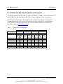
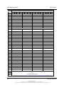
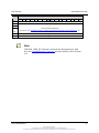
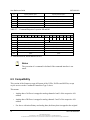
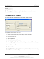
1
SST-ASI-SLC
User Guide
Document Edition: 3.0
Document #: 715-0010
User Reference Guide
SST-ASI-SLC
Document Edition: 3.0
Date: June 24, 2008
This document applies to the SST-ASI-SLC AS-Interface (As-i) Scanner module for the
SLC 500 interface card.
©2008 Woodhead Industries Inc. All rights reserved.
This document and its contents are the proprietary and confidential property of Woodhead
Industries Inc. and/or its related companies and may not be used or disclosed to others without
the express prior written consent of Woodhead Industries Inc. and/or its related companies.
SST is a trademark of Woodhead Industries Inc. All other trademarks belong to their respective
companies.
At Woodhead, we strive to ensure accuracy in our documentation. However, due to rapidly
evolving products, software or hardware changes occasionally may not be reflected in our
documents. If you notice any inaccuracies, please contact us (see Appendix E of this document).
Written and designed at Woodhead Software & Electronics, 50 Northland Road,
Waterloo, Ontario, Canada N2V 1N3.
Hardcopies are not controlled.
ii
©2008 Woodhead Industries Inc.
Document Edition: 3.0, Document #: 715-0010, Template Edition: 1.1, Template #: QMS-06-045
Use, duplication or disclosure of this document or any of the information contained herein is subject to the restrictions on page ii of this document.
Contents
Preface ......................................................................................................................... vii
Purpose of this Guide ............................................................................................................... viii
Who Should Use this Guide? ................................................................................................... viii
Conventions ................................................................................................................................ ix
Style......................................................................................................................................... ix
Terminology ..............................................................................................................................x
Special Notation ...................................................................................................................... xi
Overview ...................................................................................................................... 13
1.1 System Overview..................................................................................................................14
1.2 Hardware Features................................................................................................................15
1.2.1 LEDs...............................................................................................................................16
1.2.2 4-pin Phoenix Combicon Connectors ............................................................................16
1.2.3 Configuration Port..........................................................................................................16
1.3 Software Installation.............................................................................................................16
Scanner Quick Start .................................................................................................... 17
2.1 Overview ..............................................................................................................................18
2.2 Equipment and Tools............................................................................................................18
2.3 Procedures ............................................................................................................................19
Contents
iii
©2008 Woodhead Industries Inc.
Document Edition: 3.0, Document #: 715-0010, Template Edition: 1.1, Template #: QMS-06-045
Use, duplication or disclosure of this document or any of the information contained herein is subject to the restrictions on page ii of this document.
User Reference Guide
SST-ASI-SLC
Theory of Operation .................................................................................................... 23
3.1 The AS-Interface ..................................................................................................................24
3.2 Scanner Overview ................................................................................................................24
3.3 Configuring the AS-i Scanner ..............................................................................................26
3.3.1 G File vs. USB Port Configuration ................................................................................26
3.3.2 G File Configuration ......................................................................................................26
3.3.3 Configuring the USB Port ..............................................................................................28
3.3.4 Saving to the EEPROM..................................................................................................28
3.4 Configuring Slaves ...............................................................................................................28
3.4.1 Programming Slaves ......................................................................................................28
3.4.2 Replacing Slaves ............................................................................................................29
3.4.3 Slave Parameters ............................................................................................................29
3.5 LAS/LDS/SDL/LPF .............................................................................................................30
3.6 AS-i Modes...........................................................................................................................31
3.6.1 Configuration Mode .......................................................................................................31
3.6.2 Protected Mode ..............................................................................................................31
3.7 Power-up Sequence ..............................................................................................................32
3.8 AS-i Faults............................................................................................................................32
3.9 Clearing Faults......................................................................................................................33
Installing and Wiring the Scanner Module ................................................................ 35
4.1 Installing the Scanner Module..............................................................................................36
4.1.1 Removing the Scanner Module ......................................................................................38
4.2 Wiring...................................................................................................................................38
4.2.1 AS-i Wiring ....................................................................................................................38
4.2.2 USB port Wiring ............................................................................................................39
Configuring the Master and Slaves ........................................................................... 41
5.1 Configuring the Scanner with RSLogix 500 ........................................................................42
5.2 Using Hyperterminal to Access the Scanner via the USB Port............................................44
5.3 Example of Slave Configuration ..........................................................................................44
5.4 Running the Scanner.............................................................................................................49
5.4.1 SLC Modes.....................................................................................................................49
5.4.2 SLC Fault Codes ............................................................................................................49
SLC File Reference...................................................................................................... 51
6.1 G File ....................................................................................................................................52
6.1.1 Option Bit Description ...................................................................................................52
6.1.2 Fixed G File Size Examples ...........................................................................................56
6.1.3 G File Variable Size (Compressed)................................................................................59
6.1.4 G File Variable Size (Compressed) Examples...............................................................60
6.2 Input and Output Files ..........................................................................................................61
iv
Contents
©2008 Woodhead Industries Inc.
Document Edition: 3.0, Document #: 715-0010, Template Edition: 1.1, Template #: QMS-06-045
Use, duplication or disclosure of this document or any of the information contained herein is subject to the restrictions on page ii of this document.
SST-ASI-SLC
User Reference Guide
6.3 M0 and M1 Files ..................................................................................................................63
6.3.1 Status Flag Bytes - Byte 1 (Low Byte of Word 84) .......................................................68
6.3.2 Status Flag Bytes - Byte 2 (High Byte of Word 84) ......................................................68
6.3.3 Configuring Type S-7.4 Analog and Combined Transaction Type 2 Profile Slaves.....69
6.4 Command Interface Structure...............................................................................................71
6.5 Compatibility ........................................................................................................................72
Upgrading the Scanner Firmware .............................................................................. 75
7.1 Overview ..............................................................................................................................76
7.2 Upgrading the Firmware.......................................................................................................76
Troubleshooting .......................................................................................................... 79
8.1 LED Status and SLC Fault Codes ........................................................................................80
8.2 AS-i Power Failure ...............................................................................................................81
8.3 Slave Failure .........................................................................................................................81
8.3.1 One Slave Has Failed .....................................................................................................81
8.3.2 Multiple Slaves Have Failed ..........................................................................................81
8.4 An Important Note on AS-i Faults .......................................................................................82
8.5 Other Troubleshooting Tips .................................................................................................82
8.5.1 Nothing Shows up in a List Command ..........................................................................82
8.5.2 Can't Find a Failed Slave................................................................................................83
8.5.3 Unable to go Online .......................................................................................................83
8.5.4 Slaves Don't Have AS-i power.......................................................................................83
8.5.5 Two Masters on Network...............................................................................................83
8.5.6 Error Message: “Error during transmission via AS-i bus”.............................................83
8.5.7 Replaced Slave Didn’t Auto Address.............................................................................84
M0 and M1 Files........................................................................................................... 85
A.1 Overview .............................................................................................................................86
A.2 Addressing M0 and M1 Files ..............................................................................................86
A.2.1 Restrictions on Using M0-M1 Data File Addresses......................................................87
A.2.2 Monitoring Bit Addresses .............................................................................................87
Technical Specifications ............................................................................................ 89
B.1 Specifications.......................................................................................................................90
Conformance Statement............................................................................................. 91
C.1 ASI Protocol Implementation Conformance Statement (PICS) ..........................................92
C.1.1 List of Implemented Functions......................................................................................93
C.1.2 List of All Commands ...................................................................................................95
CE Compliance ............................................................................................................ 99
D.1 CE Compliance..................................................................................................................100
Contents
v
©2008 Woodhead Industries Inc.
Document Edition: 3.0, Document #: 715-0010, Template Edition: 1.1, Template #: QMS-06-045
Use, duplication or disclosure of this document or any of the information contained herein is subject to the restrictions on page ii of this document.
User Reference Guide
SST-ASI-SLC
Warranty and Support............................................................................................... 101
E.1 Warranty.............................................................................................................................102
E.2 Reference Documents ........................................................................................................102
E.3 Technical Support ..............................................................................................................102
E.3.1 Getting Help.................................................................................................................103
Index........................................................................................................................... 105
vi
Contents
©2008 Woodhead Industries Inc.
Document Edition: 3.0, Document #: 715-0010, Template Edition: 1.1, Template #: QMS-06-045
Use, duplication or disclosure of this document or any of the information contained herein is subject to the restrictions on page ii of this document.
Preface
Preface Sections:
•
Purpose of this Guide
•
Who Should Use this Guide?
•
Conventions
Warning
Only qualified electrical personnel familiar with the construction/
operation of this equipment and the hazards involved should install,
adjust, operate, and/or service this equipment. Read and understand this
guide in its entirety before proceeding. Failure to observe this precaution
could result in severe bodily injury or, in extreme cases, loss of life.
Preface
vii
©2008 Woodhead Industries Inc.
Document Edition: 3.0, Document #: 715-0010, Template Edition: 1.1, Template #: QMS-06-045
Use, duplication or disclosure of this document or any of the information contained herein is subject to the restrictions on page ii of this document.
User Reference Guide
SST-ASI-SLC
Purpose of this Guide
This manual explains how to install, configure and operate the SST-ASI-SLC Scanner.
Who Should Use this Guide?
Use this manual if you are designing, installing, programming or troubleshooting control systems
that use Allen-Bradley SLC processors and the SST-ASI-SLC Scanner.
You should understand PLCs and have basic knowledge of SLC products. Familiarity with
AS-Interface (AS-i) modules and the AS-I network would be an asset.
Refer to your RS Logix 500 documentation for help on that software.
viii
Preface
©2008 Woodhead Industries Inc.
Document Edition: 3.0, Document #: 715-0010, Template Edition: 1.1, Template #: QMS-06-045
Use, duplication or disclosure of this document or any of the information contained herein is subject to the restrictions on page ii of this document.
SST-ASI-SLC
User Reference Guide
Conventions
This guide uses stylistic conventions, special terms, and special notation to help enhance your
understanding.
Style
The following stylistic conventions are used throughout this guide:
Bold
indicates field names, button names, tab names, executable files,
and options or selections
Italics
indicates keywords (indexed) or instances of new terms and/or specialized
words that need emphasis
CAPS
indicates a specific key selection, such as ENTER, TAB, CTRL, ALT,
DELETE
Code Font
indicates command line entries or text that you’d type into a field
Underlining
indicates a hyperlink
“>” delimiter
indicates how to navigate through a hierarchy of menu selections/options
“0x”
indicates a hexadecimal value
Preface
ix
©2008 Woodhead Industries Inc.
Document Edition: 3.0, Document #: 715-0010, Template Edition: 1.1, Template #: QMS-06-045
Use, duplication or disclosure of this document or any of the information contained herein is subject to the restrictions on page ii of this document.
User Reference Guide
SST-ASI-SLC
Terminology
The following special terms are used throughout this guide:
Card
The SLC 500 network interface card
Channel
An AS-i network interface on the card
Firmware Module
The embedded software module that gets loaded to the card’s
memory and runs on the card. This is the operating system of the
card, enabling it to respond to commands from the host and
manage network communications.
Scanner
The SST-ASI-SLC Scanner module, consisting of hardware and
firmware.
x
Preface
©2008 Woodhead Industries Inc.
Document Edition: 3.0, Document #: 715-0010, Template Edition: 1.1, Template #: QMS-06-045
Use, duplication or disclosure of this document or any of the information contained herein is subject to the restrictions on page ii of this document.
SST-ASI-SLC
User Reference Guide
Special Notation
The following special notations may be used throughout this guide:
Warning
Warning messages alert the reader to situations where personal injury
may result. Warnings are accompanied by the symbol shown, and
precede the topic to which they refer.
Caution
Caution messages alert the reader to situations where equipment damage
may result. Cautions are accompanied by the symbol shown, and
precede the topic to which they refer.
Note
A note provides additional information, emphasizes a point, or gives a
tip for easier operation. Notes are accompanied by the symbol shown,
and follow the text to which they refer.
Preface
xi
©2008 Woodhead Industries Inc.
Document Edition: 3.0, Document #: 715-0010, Template Edition: 1.1, Template #: QMS-06-045
Use, duplication or disclosure of this document or any of the information contained herein is subject to the restrictions on page ii of this document.
User Reference Guide
xii
SST-ASI-SLC
Preface
©2008 Woodhead Industries Inc.
Document Edition: 3.0, Document #: 715-0010, Template Edition: 1.1, Template #: QMS-06-045
Use, duplication or disclosure of this document or any of the information contained herein is subject to the restrictions on page ii of this document.
SST-ASI-SLC
User Reference Guide
1
Overview
Chapter Sections:
•
System Overview
•
Hardware Features
Overview
13
©2008 Woodhead Industries Inc.
Document Edition: 3.0, Document #: 715-0010, Template Edition: 1.1, Template #: QMS-06-045
Use, duplication or disclosure of this document or any of the information contained herein is subject to the restrictions on page ii of this document.
User Reference Guide
SST-ASI-SLC
1.1 System Overview
The SST-ASI-SLC is the AS-Interface (AS-i) Scanner for the SLC 500. It allows an SLC
processor (SLC 5/03 or later) and AS-i modules to communicate on the AS-i network.
The Scanner supports 2 AS-i channels.
You can configure the AS-i network with the SLC G file or with the Scanner’s Config
USB port.
The Scanner can occupy any slot in the local SLC chassis except slot 0, which is reserved for the
SLC processor. You can have multiple Scanners in the same rack.
The digital input and output data for the slaves is mapped into SLC I and O files. SLC M0 and
M1 files store analog data and network status information.
14
Overview
©2008 Woodhead Industries Inc.
Document Edition: 3.0, Document #: 715-0010, Template Edition: 1.1, Template #: QMS-06-045
Use, duplication or disclosure of this document or any of the information contained herein is subject to the restrictions on page ii of this document.
SST-ASI-SLC
User Reference Guide
1.2 Hardware Features
Figure 1: Front of AS-i Scanner
The following table describes the parts of the Scanner. The side label of the Scanner provides
module information.
Table 1: Scanner Parts
Feature
Description
COMM 1 and COMM 2 LEDs
Display the communication status for each
channel.
FAULT LED
Displays the fault status.
4-pin Phoenix connectors
(AS-i Ch 1 and AS-i Ch 2)
Connections to AS-i networks.
USB port
Used for configuring I/O.
Overview
15
©2008 Woodhead Industries Inc.
Document Edition: 3.0, Document #: 715-0010, Template Edition: 1.1, Template #: QMS-06-045
Use, duplication or disclosure of this document or any of the information contained herein is subject to the restrictions on page ii of this document.
User Reference Guide
SST-ASI-SLC
1.2.1 LEDs
The Scanner has three LEDs: the FAULT LED, and one COMM LED for each AS-i network. At
power-up, they flash for 1 second.
Refer to Section 8.1, LED Status and SLC Fault Codes, for detailed information on what these
LEDs indicate.
When the SLC is in Program mode, all LEDs are normally off.
FAULT LED
The FAULT LED indicates the overall status of Scanner operations.
COMM LEDs
The COMM LED displays the status of the respective channel. If there are no network errors and
the SLC is in Run mode, the COMM LEDs are green.
1.2.2 4-pin Phoenix Combicon Connectors
Each connector allows you to connect the Scanner to an AS-i network, and consists of 2 sets of 2
pins. Pins 1 and 3 are internally connected, as are 2 and 4.
You can connect AS-I power to one set of pins and the AS-i network to the other.
1.2.3 Configuration Port
The configuration port is a USB type B female connector (USB port). It is used for field
upgrades of module firmware and for configuration of AS-I slave addresses and information.
1.3 Software Installation
Before using the USB port to set the slave address, configure the list of slaves in the EEPROM,
or update the firmware. You will need to install the Virtual COM Port driver and the Upgrading
firmware utility tool, which are on the AS-I product CD.
16
Overview
©2008 Woodhead Industries Inc.
Document Edition: 3.0, Document #: 715-0010, Template Edition: 1.1, Template #: QMS-06-045
Use, duplication or disclosure of this document or any of the information contained herein is subject to the restrictions on page ii of this document.
SST-ASI-SLC
User Reference Guide
2
Scanner Quick Start
Chapter Sections:
•
Overview
•
Equipment and Tools
•
Procedures
Scanner Quick Start
©2008 Woodhead Industries Inc.
Document Edition: 3.0, Document #: 715-0010, Template Edition: 1.1, Template #: QMS-06-045
Use, duplication or disclosure of this document or any of the information contained herein is subject to the restrictions on page ii of this document.
17
User Reference Guide
SST-ASI-SLC
2.1 Overview
This chapter provides all the necessary information to get you up and running quickly. It:
•
Tells you which tools and equipment you need
•
Describes how to configure and program the Scanner module
•
Explains how to install the Scanner module
•
Discusses system power-up procedures
This chapter does not include detailed explanations of these procedures, but refers to later
sections and chapters. If you have any questions or are unfamiliar with the terms used or
concepts presented, read the referenced chapters and other documentation before you proceed.
2.2 Equipment and Tools
Have the following tools and equipment ready:
18
•
SLC programming equipment
•
Virtual COM Port Drivers
•
Firmware upgrade utility (flasher.exe)
•
Terminal emulation software
•
a USB A-B Cable, M/M
•
AS-i cable to connect the Scanner to the AS-i network
•
AS-i power supply
Scanner Quick Start
©2008 Woodhead Industries Inc.
Document Edition: 3.0, Document #: 715-0010, Template Edition: 1.1, Template #: QMS-06-045
Use, duplication or disclosure of this document or any of the information contained herein is subject to the restrictions on page ii of this document.
SST-ASI-SLC
User Reference Guide
2.3 Procedures
To get the Scanner up and running, follow these procedures:
1. Unpack the module. Make sure you received the AS-i Scanner and a USB A-B M/M
cable for configuring I/O.
2. Install the Virtual COM Port driver on your PC.
3. Review your system's power requirements to verify that your chassis supports the
Scanner module. The Scanner consumes 120 mA at 5 VDC.
4. Calculate the total load on the system power supply using the procedure described in the
SLC 500 Modular Style Installation & Operation Manual, Allen-Bradley Publication
1747-6.2, or the SLC 500 Family System Overview, Publication 1747-2.30.
5. Make sure system power is off.
6. Insert the Scanner module into your 1746 chassis.
7. Connect AS-i power to the Scanner. The slaves require AS-i power to be able to
communicate with the Scanner. Refer to Chapter 4, Installing and Wiring the Scanner
Module, for more details.
8. Set up your system I/O configuration for the relevant Scanner slot. Using RSLogix 500
software, configure the Scanner as Other and enter the Scanner module ID (13635).
Refer to Chapter 5, Configuring the Master and Slaves, for details on configuring the
Scanner with several popular programming packages. Refer to Section 5.1, Configuring
the Scanner with RSLogix 500, for important information on dealing with a G file
problem in RSLogix.
Note
Beginning in version 5.0 of RSLogix500, this ID is identified as a BLM
Module. Overwrite the file sizes with the values below.
Scanner Quick Start
©2008 Woodhead Industries Inc.
Document Edition: 3.0, Document #: 715-0010, Template Edition: 1.1, Template #: QMS-06-045
Use, duplication or disclosure of this document or any of the information contained herein is subject to the restrictions on page ii of this document.
19
User Reference Guide
SST-ASI-SLC
9. Set the M1 and M0 file sizes to 337 words.
10. Set scanned inputs and outputs to 32 words.
11. Set the G file size to 160 words.
Note
If using the Scanner in compatibility mode refer to Section 6.5 for the
file sizes,
12. Modify the G file. For details on G file layout and configuration, refer to Section 6.1,
G File. Set the following words to enable Channel 1:
•
Word 1 - 1
•
Word 80 - 0
•
Word 159 - 3543h (13635 decimal) (Scanner module ID)
•
All other words can be set to 0000h
Once you verify your system is operating correctly, you can configure the rest of the
network in the G file.
13. Use the provided USB A-B M/M cable to connect the Scanner to your configuration
computer via the USB port.
14. Run your terminal emulation software.
15. Set the baud rate to 38400 and the parameters to No parity, 8 data bits and one Stop bit,
no flow control.
16. With the SLC CPU in PROG/REM PROG mode, press the [*] key to get the Scanner’s
attention, and choose Network 1 to configure.
17. Hook up AS-i power and add an AS-i slave.
18. In your terminal software, perform a List command and verify that the slave appears on
the network. If the slave is listed at Address 0, use the Address command to change it to
the desired address. Refer to Section 5.3, Example of Slave Configuration, for an
example of configuring a slave. Continue adding slaves and setting their addresses.
19. Save the configuration and exit Config mode.
20
Scanner Quick Start
©2008 Woodhead Industries Inc.
Document Edition: 3.0, Document #: 715-0010, Template Edition: 1.1, Template #: QMS-06-045
Use, duplication or disclosure of this document or any of the information contained herein is subject to the restrictions on page ii of this document.
SST-ASI-SLC
User Reference Guide
20. Put the SLC in Run mode. The Scanner module begins scanning I/O.
21. Verify that you can read inputs and write outputs.
Scanner Quick Start
©2008 Woodhead Industries Inc.
Document Edition: 3.0, Document #: 715-0010, Template Edition: 1.1, Template #: QMS-06-045
Use, duplication or disclosure of this document or any of the information contained herein is subject to the restrictions on page ii of this document.
21
SST-ASI-SLC
User Reference Guide
3
Theory of Operation
Chapter Sections:
•
The AS-Interface
•
Scanner Overview
•
Configuring the AS-i Scanner
•
Configuring Slaves
•
LAS/LDS/SDL/LPF
•
AS-i Modes
•
Power-up Sequence
•
AS-i Faults
•
Clearing Faults
Theory of Operation
©2008 Woodhead Industries Inc.
Document Edition: 3.0, Document #: 715-0010, Template Edition: 1.1, Template #: QMS-06-045
Use, duplication or disclosure of this document or any of the information contained herein is subject to the restrictions on page ii of this document.
23
User Reference Guide
SST-ASI-SLC
3.1 The AS-Interface
The AS-Interface (AS-i) is a master-slave network that offers reliable, inexpensive digital
communications, to sensors and actuators, for low-level automation.
The network supports up to 31 slaves or up to 62 slaves with extended addressing, and a
maximum cable length of 100 m.
With repeaters (2 maximum), the length can reach a maximum of 300m. The AS-i cabling
contains data and power on a single cable, making setup extremely easy.
3.2 Scanner Overview
Figure 2: Scanner Block Diagram
24
Theory of Operation
©2008 Woodhead Industries Inc.
Document Edition: 3.0, Document #: 715-0010, Template Edition: 1.1, Template #: QMS-06-045
Use, duplication or disclosure of this document or any of the information contained herein is subject to the restrictions on page ii of this document.
SST-ASI-SLC
User Reference Guide
The Scanner firmware is stored in flash memory on the module. The current version is 3.x.x,
and it supports AS-i 3.0 functions.
Note
Although this version is compatible with SLC programs written
for version 1.x., we recommend using the Scanner's new features.
Refer to Section 6.5, Compatibility, for more details.
Each channel's EEPROM contains the network configuration. You can store a network
configuration in the EEPROM in one of two ways:
•
Connect to the USB port, select a channel and save
•
Set the G bit in the G file, create a configuration in the G file and download the program
to the SLC. When you put the SLC in Run mode, it writes the configuration from the
G file to the EEPROM.
In either case, when you switch the SLC to Run mode, the SLC compares the contents of the
EEPROM with the network and, if they match, it starts updating I/O. If they don't match, it
generates a fault.
Theory of Operation
©2008 Woodhead Industries Inc.
Document Edition: 3.0, Document #: 715-0010, Template Edition: 1.1, Template #: QMS-06-045
Use, duplication or disclosure of this document or any of the information contained herein is subject to the restrictions on page ii of this document.
25
User Reference Guide
SST-ASI-SLC
3.3 Configuring the AS-i Scanner
When you first configure your AS-i system, you must initially set some basic options in the
G file. Then you may enter and manipulate the rest of your network configuration, using either
the G file or the USB port. This section discusses both methods of configuration.
3.3.1 G File vs. USB Port Configuration
When you are connecting the Scanner to an existing (and present) network, the USB port method
is much quicker than the G file method. However, it does not save the network configuration as
part of the SLC program.
The G file method saves the configuration and allows you to archive and load it onto another
system. If the Scanner fails, you can easily replace the failed device and reconfigure the system
with the archived G file. To configure the G file more easily, you can connect to an existing
network, and using the USB port, have the Scanner display a compatible G file configuration for
entry into your program.
3.3.2 G File Configuration
Option bits in the G file affect the way the Scanner operates with respect to parameters and
I and O file usage.
You must do at least some configuration via the G file. At a minimum, you must set the Scanner
ID and indicate the AS-i channel(s) you are using. If you try to run without setting these bits in
the G file, the Scanner will fault with a G file error (70H).
There are 3 parts within the G file. The first two are the configuration for each of the two
channels. The third is a single word containing the module ID, which indicates the end of the G
file. This word is usually contained in word 159.
26
Theory of Operation
©2008 Woodhead Industries Inc.
Document Edition: 3.0, Document #: 715-0010, Template Edition: 1.1, Template #: QMS-06-045
Use, duplication or disclosure of this document or any of the information contained herein is subject to the restrictions on page ii of this document.
SST-ASI-SLC
User Reference Guide
The first word in each channel's configuration contains options bits. These are:
•
Bit 0 – enables the channel
•
Bit 1 – enables extended addressing (expands the number of slaves from 31 to 62 –
requires special slaves to work).
•
Bit 2 – enables auto address programming
•
Bit 3 – enables the SLC to write parameters to the slaves; WParam from the M file is
used, and slave Param echoes are put into different locations in M file (refer to M file
layout).
If you do not set the bit(s), the M file parameters are ignored.
•
Bit 4 – mLAS – if set, the top portion of the channel's input table is replaced with the
channel's list of active slaves. Refer to Section 6.2, Input and Output Files, for more
details.
•
Bit 5 –mSDL – if set, the top portion of the channel's input table is replaced with the list
of missing slaves. Refer to Section 6.2, Input and Output Files, for more details.
•
Bit 6 – mLPF – if set, the top portion of the channel's input table is replaced with list of
slaves' peripheral fault status. Refer to Section 6.2, Input and Output Files, for more
details.
•
Bit 8 – Fault Bit – if set, the SLC will continue to operate when any AS-i fault on this
channel occurs.
•
Bit 12 – G file – if set, the G file contains slave configuration data.
•
Bit 13 – Parameter – if set, the slave parameters from the G file are used.
•
Bit 14 – Compress G file – if set, the G file length is reduced by skipping unused portions
for this channel.
•
Other bits are reserved and should be left as 0.
Theory of Operation
©2008 Woodhead Industries Inc.
Document Edition: 3.0, Document #: 715-0010, Template Edition: 1.1, Template #: QMS-06-045
Use, duplication or disclosure of this document or any of the information contained herein is subject to the restrictions on page ii of this document.
27
User Reference Guide
SST-ASI-SLC
3.3.3 Configuring the USB Port
You can use the USB port to set slave addresses, to configure the list of slaves in the EEPROM
or to update the firmware.
When configuring from or exiting the USB port, slave address changes are recorded in the
slave but not in the EEPROM. Slave parameter changes are sent to the slave when they are
made, but they are not stored in EEPROM until you use the Save command, or exit and choose
the Save command.
When the AS-Interface enters Protected mode, only those slaves in the EEPROM are activated.
3.3.4 Saving to the EEPROM
Information is only saved to the EEPROM in four instances:
•
When the configuration in the G file is different than the network's, the G bit is set and
the SLC is set to run
•
When you issue the command request in the M0 and M1 file, which changes permanent
data (PCD, LPS, PP, operation mode and auto address enable)
•
When you issue the Save command from the USB port
•
When you exit and choose the Save command
3.4 Configuring Slaves
3.4.1 Programming Slaves
“Out of the box” slaves are programmed for Address 0. Use one of two methods to set the
module address:
28
•
Program the address using a handheld programmer before attaching the slave to the
network.
•
Attach the slave to the network and use the AS-i Scanner USB port to change the slave
address. Slaves must be attached and addressed one at a time in this method.
Theory of Operation
©2008 Woodhead Industries Inc.
Document Edition: 3.0, Document #: 715-0010, Template Edition: 1.1, Template #: QMS-06-045
Use, duplication or disclosure of this document or any of the information contained herein is subject to the restrictions on page ii of this document.
SST-ASI-SLC
User Reference Guide
3.4.2 Replacing Slaves
If Auto Addressing is enabled, slaves can be replaced while the network is running. For example,
if a slave has failed and must be changed, you can remove it and add a new one with an address
of 0 and matching I/O and IDs. The new slave will be automatically reprogrammed to the old
slave’s address; you don’t have to configure it.
To enable Auto Address Programming, the Auto Address Programming bit (bit 2 of the
option's word) must be set in the G file. You must be in AS-i Protected mode (see Section 3.6,
AS-i Modes) and have network and SLC power ON when you replace the slave.
3.4.3 Slave Parameters
Slave parameters allow you to change the way a device operates. They are determined by the
manufacturer’s specifications and are not permanently stored in the slave.
You can set slave parameters in 3 ways: via the USB port, via the G file and via the M file.
The Scanner initially uses the slave parameters stored in EEPROM. If bit 13 of the Option word
is set, the G file parameter entries override and update the EEPROM entries. If Bit 3 of the
Option word is set, the M file parameters override any other entries. If neither bit is set, the
Scanner continues to use the EEPROM entries.
When Bit 3 is set, and you change parameters in the M file, the parameters are written to the
slave during a subsequent AS-i bus scan. Before any change-dependent logic is executed, the
user program should check the M file to ensure that the slave has successfully echoed the
parameter change.
When you configure via the USB port, the parameters are sent to the slave as soon as a change is
made. You must use the Save command to update the EEPROM.
Theory of Operation
©2008 Woodhead Industries Inc.
Document Edition: 3.0, Document #: 715-0010, Template Edition: 1.1, Template #: QMS-06-045
Use, duplication or disclosure of this document or any of the information contained herein is subject to the restrictions on page ii of this document.
29
User Reference Guide
SST-ASI-SLC
3.5 LAS/LDS/SDL/LPF
The LAS, LDS, SDL and LPF lists represent network slave status, and are maintained in
Run mode. These lists are stored in the Scanner M files: M0 for Channel 1, and M1 for
Channel 2.
The List of Detected Slaves (LDS) indicates the slaves that were found on the network,
whether they appear in the EEPROM or not. When AS-i enters Configuration mode, all slaves,
regardless of their presence in the EEPROM, are activated and listed in the LDS.
The List of Activated Slaves (LAS) contains the slaves listed in both the EEPROM of the AS-I
Scanner and the LDS. Slaves on the network are activated on AS-i power-up. Only those slaves
present in the EEPROM and found on the network are activated and only activated slaves
exchange IO data.
Slaves must match ID and I/O codes stored in the EEPROM to be activated. The Slave Delta List
(SDL) contains the slaves listed in either the EEPROM or the LDS, but not in both. When a slave
is detected but doesn't match any slave listed in the EEPROM, it is listed in the SDL.
The List of Peripheral Faults (LPF) contains the slaves that have declared a peripheral fault.
For each bit of the LAS, LDS and LPF, 1 represents a present slave and 0 represents an absent
slave. For SDL, 1 indicates a discrepancy between EEPROM and LDS and 0 indicates a match
between EEPROM and LDS. Refer to Section 6.3, M0 and M1 Files, for more information.
For details on mapping the above bits to the input table, refer to Section 6.1, G File.
30
Theory of Operation
©2008 Woodhead Industries Inc.
Document Edition: 3.0, Document #: 715-0010, Template Edition: 1.1, Template #: QMS-06-045
Use, duplication or disclosure of this document or any of the information contained herein is subject to the restrictions on page ii of this document.
SST-ASI-SLC
User Reference Guide
3.6 AS-i Modes
AS-i has 2 operating modes: Configuration and Protected. Normally, the system is in
Protected mode. You can enter Configuration mode only if you are configuring via the USB port.
The following sections describe each mode.
3.6.1 Configuration Mode
In Configuration mode, you can:
•
Change slave addresses
•
Save to EEPROM
In Configuration Mode, you cannot:
•
Perform data exchanges
•
Use Auto Address Programming
All slaves are active, regardless of the EEPROM. In other words, the LDS and the LAS are
identical. Refer to Section 3.5, LAS/LDS/SDL/LPF, for more information on LDS and LAS.
3.6.2 Protected Mode
In Protected mode, you can:
•
Exchange data
•
Use Auto Address Programming (if enabled)
In Protected mode, you cannot:
•
Write to EEPROM
•
Enter protected mode with Slave 0 (zero) present
•
Change slave addresses
Only those slaves present in the EEPROM and matching the ID and I/O codes in the EEPROM
are activated for data exchange.
Theory of Operation
©2008 Woodhead Industries Inc.
Document Edition: 3.0, Document #: 715-0010, Template Edition: 1.1, Template #: QMS-06-045
Use, duplication or disclosure of this document or any of the information contained herein is subject to the restrictions on page ii of this document.
31
User Reference Guide
SST-ASI-SLC
3.7 Power-up Sequence
The power-up sequence is as follows:
1. When the SLC goes into Run mode, the module parses the G file and configures the
network controller appropriately. If the G file specifies a change from the current
projected network, the module updates the EEPROM on the network controller to change
the list of projected slaves.
2. The module sends the parameters to the slaves and begins bus scanning.
3.8 AS-i Faults
If an error occurs in Run mode, the Scanner interrogates bit 8 of the channel's options word in
the G File to determine whether to fault the SLC processor. This fault may be a recoverable
major fault. If an error handler routine is installed (S:29), it can determine the type of fault (S:6)
and act appropriately. If the error routine clears the major error flag (S2:1/13), the SLC will try
to continue in Run mode.
AS-i faults cannot be corrected by the Scanner, as user intervention is required. However, if you
want to continue scanning, you can set the Fault Acknowledge bits and the Scanner will ignore
the error until it reoccurs. The Fault Acknowledge bits are the 4 least significant bits of word 0
in the Output file. Set Bit 0 to acknowledge error 61h, bit 1 for 62h, bit 2 for 63h and bit 3 for
64h.
Note
63h and 64h are reserved for future use.
32
Theory of Operation
©2008 Woodhead Industries Inc.
Document Edition: 3.0, Document #: 715-0010, Template Edition: 1.1, Template #: QMS-06-045
Use, duplication or disclosure of this document or any of the information contained herein is subject to the restrictions on page ii of this document.
SST-ASI-SLC
User Reference Guide
The fault bits may be set ahead of time (at start-up) or during the error handling routine. If they
are set during the error handling routine, you will have to do an IOM instruction, which performs
an immediate write. Refer to Figure 3, IOM Ladder Logic Instruction, for more details.
Note
With some versions of the SLC, if your program clears the main error
flag (S2:1/13), subsequent faults on other modules or the SLC processor
might not be reported to the Scanner and the Scanner will continue
scanning, even if the SLC is faulted.
If an error occurs during the error recovery process or is found in the G file, the fault will be
indicated as non-recoverable. The error handler will still execute, but the SLC will be unable to
clear the major error flag and the Scanner will stop.
3.9 Clearing Faults
When you cycle the SLC from Program to Run, the fault is cleared if the cause of the fault has
been removed.
Figure 3: IOM Ladder Logic Instruction
Theory of Operation
©2008 Woodhead Industries Inc.
Document Edition: 3.0, Document #: 715-0010, Template Edition: 1.1, Template #: QMS-06-045
Use, duplication or disclosure of this document or any of the information contained herein is subject to the restrictions on page ii of this document.
33
SST-ASI-SLC
User Reference Guide
4
Installing and Wiring the Scanner Module
Chapter Sections:
•
Installing the Scanner Module
•
Wiring
Installing and Wiring the Scanner Module
©2008 Woodhead Industries Inc.
Document Edition: 3.0, Document #: 715-0010, Template Edition: 1.1, Template #: QMS-06-045
Use, duplication or disclosure of this document or any of the information contained herein is subject to the restrictions on page ii of this document.
35
User Reference Guide
SST-ASI-SLC
4.1 Installing the Scanner Module
Installation procedures for the Scanner module are the same as for any other module. Refer to
Figure 4 to identify the chassis and module components listed in the installation procedures.
Caution
Disconnect system power before attempting to install, remove or wire
the Scanner. Adding or removing the module with the power on may
cause electrical damage.
Note
Before installation, make sure that your modular SLC power supply has
adequate reserve current capacity. The Scanner requires 120 mA at
5 VDC.
Figure 4: Chassis and Module Components
36
Installing and Wiring the Scanner Module
©2008 Woodhead Industries Inc.
Document Edition: 3.0, Document #: 715-0010, Template Edition: 1.1, Template #: QMS-06-045
Use, duplication or disclosure of this document or any of the information contained herein is subject to the restrictions on page ii of this document.
SST-ASI-SLC
User Reference Guide
To install the Scanner module:
1. Disconnect power.
2. Align the full-sized circuit board with the chassis card guides.
Note
The first slot (slot 0) of the first rack is reserved for the SLC 500
processor.
3. Slide the Scanner module into the chassis until the top and bottom latches catch.
4. Attach the AS-i cable. Refer to Section 4.2.1, AS-i Wiring, for cabling information.
5. Route the cable down and away from the Scanner.
6. Cover all unused slots with the card slot filler, Allen-Bradley catalog number 1746-N2.
7. Attach the USB cable between your PC and the Scanner module. For more information,
refer to Section 4.2.2, USB port Wiring.
8. Power up the system.
Note
If there is a lot of electrical noise in your installation, you need to install
an isolating transformer. For instructions, refer to Allen-Bradley’s
Installation and Operation Manual for Modular Hardware Style
Programmable Controller, AB 1747-6.2.
Installing and Wiring the Scanner Module
©2008 Woodhead Industries Inc.
Document Edition: 3.0, Document #: 715-0010, Template Edition: 1.1, Template #: QMS-06-045
Use, duplication or disclosure of this document or any of the information contained herein is subject to the restrictions on page ii of this document.
37
User Reference Guide
SST-ASI-SLC
4.1.1 Removing the Scanner Module
1. Disconnect power.
2. Remove all cabling from the Scanner.
3. Press the releases at the top and bottom of the module and slide the module out of
the slot.
4. Cover all unused slots with the card slot filler, Allen-Bradley catalog number 1746-N2.
5. Place the Scanner into the static protective bag supplied with shipment packaging and
store in the original box. Store the Scanner in a dry and cool environment.
4.2 Wiring
4.2.1 AS-i Wiring
The Scanner module uses two 4-pin Phoenix connectors, one for each AS-I channel. Pins 1 and 3
and pins 2 and 4 are internally connected for your convenience.
Figure 5: Daisy-Chained Phoenix Connector
to AS-i network
to AS-i Scanner module
to AS-i power supply
The cable type is Siemens P/N 3RX9010-0AA00. To scan I/O, you must have a certified AS-i
power supply connected to the Scanner.
If the network is daisy-chained through the Scanner, as in the above diagram, the maximum
pass-through current is 6 Amps. If the Scanner is connected in a mode other than daisy chain,
this limit is eliminated.
If you accidentally reverse the polarity on the AS-i line, it will not work but it should not be
damaged.
The SST-ASI-SLC has been tested with power sources from Woodhead (TAS-PWR-4A),
Siemens (types 3RX9303-0AA00 and 3RX9301-0AA00) and Pepperl + Fuchs (Type VAN115/230AC-K8).
38
Installing and Wiring the Scanner Module
©2008 Woodhead Industries Inc.
Document Edition: 3.0, Document #: 715-0010, Template Edition: 1.1, Template #: QMS-06-045
Use, duplication or disclosure of this document or any of the information contained herein is subject to the restrictions on page ii of this document.
SST-ASI-SLC
User Reference Guide
4.2.2 USB port Wiring
A USB-to-serial converter is integrated in the USB port. This converter is detected as COM-Port
by the PC, and any terminal programs can communicate via this port with the SST-ASI-SLC.
Note
Before you can scan I/O, you must configure your slaves using either an
addressing unit or the Scanner’s USB port.
Figure 6: USB Port
Table 1: Pin Names and Descriptions
Pin #
Pin Name
Description
1
+5
USB Power. Not Used
2
-Data
Data pin.
3
+Data
Data pin.
4
GND
USB ground.
Note
The recommended USB cable is USB A-B Cable M/M, USB A Male
and USB B Male.
For an example of configuring slaves using a communications software package over the USB
port, refer to Section 5.3, Example of Slave Configuration.
Installing and Wiring the Scanner Module
©2008 Woodhead Industries Inc.
Document Edition: 3.0, Document #: 715-0010, Template Edition: 1.1, Template #: QMS-06-045
Use, duplication or disclosure of this document or any of the information contained herein is subject to the restrictions on page ii of this document.
39
SST-ASI-SLC
User Reference Guide
5
Configuring the Master and Slaves
Chapter Sections:
•
Configuring the Scanner with RSLogix 500
•
Using Hyperterminal to Access the Scanner via the USB Port
•
Example of Slave Configuration
•
Running the Scanner
Configuring the Master and Slaves
©2008 Woodhead Industries Inc.
Document Edition: 3.0, Document #: 715-0010, Template Edition: 1.1, Template #: QMS-06-045
Use, duplication or disclosure of this document or any of the information contained herein is subject to the restrictions on page ii of this document.
41
User Reference Guide
SST-ASI-SLC
5.1 Configuring the Scanner with RSLogix 500
Follow these steps to set up the Scanner when you program your SLC system in RSLogix 500:
1. Create a new file or load an existing file.
2. Open the I/O Configuration editor.
3. Select the proper rack for your setup.
4. Highlight the slot where the AS-i Scanner is installed.
5. From the list of available cards, select Other.
6. Enter an ID number of 13635.
Note
Beginning in version 5.0 of RSLogix500 this ID is identified as a BLM
Module. Simply overwrite the file sizes with the values below.
7. Right-click on the newly configured slot and select Adv. Config.
8. Set Scanned Input Words and Scanned Output Words to 32.
9. Set M0 and M1 lengths to 337 words. Refer to Section 6.3, M0 and M1 Files,
for additional information on the M files.
10. Set G file size to 160 words.
Note
If using the Scanner in compatibility mode refer to Section 6.5 for the
file sizes.
42
Configuring the Master and Slaves
©2008 Woodhead Industries Inc.
Document Edition: 3.0, Document #: 715-0010, Template Edition: 1.1, Template #: QMS-06-045
Use, duplication or disclosure of this document or any of the information contained herein is subject to the restrictions on page ii of this document.
SST-ASI-SLC
User Reference Guide
11. Select Edit G file Data and edit the G file to match your network configuration.
Refer to Section 6.1, G File, for details on G file setup.
12. Click OK for G file editor and OK for Adv. Config.
13. Close the I/O Configuration window.
14. Write the rest of the ladder logic. Refer to Section 6.2, Input and Output Files,
and Section 6.3, M0 and M1 Files, for information on the I, O and M files.
15. Transfer the program to the SLC.
Configuring the Master and Slaves
©2008 Woodhead Industries Inc.
Document Edition: 3.0, Document #: 715-0010, Template Edition: 1.1, Template #: QMS-06-045
Use, duplication or disclosure of this document or any of the information contained herein is subject to the restrictions on page ii of this document.
43
User Reference Guide
SST-ASI-SLC
5.2 Using Hyperterminal to Access the Scanner via the
USB Port
To access the Scanner via the USB port:
1. Connect the AS-i Scanner to the PC, using the provided USB A-B cable.
2. Start HyperTerminal and create a new connection.
3. For Connect using:, select Direct to Com n, where n is the COM port (detected converter
by the PC) you are using.
4. Select 38400 Bits per second and 8 Data bits.
5. Set Parity to None, select 1 Stop Bit, and set Flow Control to None.
6. Type "*" several times.
You should now be able to communicate with the Scanner USB port. Once you have configured
the Scanner, you can configure the AS-i slaves.
5.3 Example of Slave Configuration
1. Make sure the SLC is in Program mode and run your communication software.
2. Set your communications software to use 38400 Bits per second and 8 Data bits.
Set Parity to None, select 1 Stop Bit and set Flow control to None. The Scanner
automatically detects the baud rate you are using by adjusting it until an “*” has been
received correctly.
You may have to type the asterisk several times so that the Scanner can detect the
baud rate. When the Scanner properly receives your “*”, the following prompt appears:
***** Slave Configuration Activated *****
AS-I 3.0 ASI-SLC Module
Firmware version 3.0
Which Channel do you want to configure? (1 or 2) _
The FAULT and COMM 1 LEDs will now be alternately blinking red to indicate
Configuration mode is active.
44
Configuring the Master and Slaves
©2008 Woodhead Industries Inc.
Document Edition: 3.0, Document #: 715-0010, Template Edition: 1.1, Template #: QMS-06-045
Use, duplication or disclosure of this document or any of the information contained herein is subject to the restrictions on page ii of this document.
SST-ASI-SLC
User Reference Guide
3. Enter 1 or 2 to select the channel to configure. This example configures Channel 1:
Configuring Channel 1
Commands: Address, Parameter, ID, List, GFile, Save, Exit, Help
Config :>
The Config:> prompt lets you know that you are currently in Configuration mode.
The available commands are listed above the prompt. Use the Help command for more
information.
4. Attach a slave with an address of 0 to the network and type List to verify its presence:
Config :> list
Slave IO
ID
ID2 ID1 P
00
0
F
8
F
F
Sts
PF
PIO PID ID2 ID1 P
In
Out
0
PID, PIO and the following ID2 and ID1 fields are Projected ID and I/O values.
The fields are empty at this time because the values are not yet stored in EEPROM.
5. Once you have verified that your slave is present, you can change its network address
using the Address command. In this example, Slave 0 is changed to Slave 3:
Config :> address
Enter slave # to change: 0
Enter new # for slave 00: 3
For slaves that don’t accept extended addressing, you can assign addresses 1 to 31.
For slaves that accept extended addressing, you can assign addresses 1 to 31 and 1B
to 31B.
Configuring the Master and Slaves
©2008 Woodhead Industries Inc.
Document Edition: 3.0, Document #: 715-0010, Template Edition: 1.1, Template #: QMS-06-045
Use, duplication or disclosure of this document or any of the information contained herein is subject to the restrictions on page ii of this document.
45
User Reference Guide
SST-ASI-SLC
6. Verify the operation using the List command:
Config :> list
Slave IO
ID
ID2 ID1 P
03
0
F
8
F
F
Sts
PF
PIO PID ID2 ID1 P
In
Out
0
7. If everything is OK, add a new slave at Address 0. Verify using the List command:
Config :> list
Slave IO
ID
ID2 ID1 P
Sts
00
8
0
F
F
F
0
03
0
0
F
F
F
0
PF
PIO PID ID2 ID1 P
In
Out
8. Continue to add slaves, assign addresses and verify operations until all slaves have been
added:
Config :> address
Enter slave # to change: 0
Enter new # for slave 00: 1
Config :> list
46
Slave IO
ID
ID2 ID1 P
Sts
01
8
0
F
F
F
0
03
0
0
F
F
F
0
PF
PIO PID ID2 ID1 P
In
Out
Configuring the Master and Slaves
©2008 Woodhead Industries Inc.
Document Edition: 3.0, Document #: 715-0010, Template Edition: 1.1, Template #: QMS-06-045
Use, duplication or disclosure of this document or any of the information contained herein is subject to the restrictions on page ii of this document.
SST-ASI-SLC
User Reference Guide
9. Save the configuration and perform a List command:
Config :> save
Saving....
EEPROM write was successful.
Config :> list
Slave IO
ID
ID2 ID1 P
Sts
PF
PIO PID ID2 ID1 P
01
8
0
F
F
F
0
8
0
F
F
F
03
0
0
F
F
F
0
0
0
F
F
F
In
Out
The PID, PIO and projected ID1 and ID2 values are now saved in EEPROM so they
appear in the display. If a slave has PID and PIO values displayed without corresponding
ID and I/O values, that slave has failed or is missing.
10. When you are finished, type Exit. You will be prompted to save any outstanding
changes. These will be saved to the EEPROM on the module:
Config :> exit
SAVE changes before exiting? (Y or N) y
Saving...
EEPROM write was successful.
With ASI 2.1-compatible slaves, there are 2 additional fields (ID1 and ID2).
When the Scanner performs slave comparisons (auto addressing to replace a slave or
going online) it compares ID, IO, ID1 and ID2 for a match. ID2 allows manufacturers to
further discriminate between different types of slaves
To allow you to discriminate as well, ID1 has been provided and can be set in the field.
You can modify the ID1 by using the ID command in Configuration mode. If you are
using slaves that have the same profile, yet are different in some physical manner, you
can use ID1 to allow the Scanner to tell them apart. That way, if someone tries to auto
address a physically incompatible slave, the Scanner will not allow it.
Configuring the Master and Slaves
©2008 Woodhead Industries Inc.
Document Edition: 3.0, Document #: 715-0010, Template Edition: 1.1, Template #: QMS-06-045
Use, duplication or disclosure of this document or any of the information contained herein is subject to the restrictions on page ii of this document.
47
User Reference Guide
Slave IO
31B 0
SST-ASI-SLC
ID
A
ID2 ID1 P
E
A
2
Sts
0
PF
PIO PID ID2 ID1 P
0
A
E
A
2
In
Out
If you have set up a network, you can use the G file command to list the contents of a
G file which reproduces the network configuration. This G file can then be copied into
your program.
Config :> gfile
Offset 001: 7003
Offset 002: FFFF FFFF FFFF FFFF FFFF FFFF FFFF FFFF
Offset 010: 00EF 70FF FFFF FFFF FFFF FFFF FFFF FFFF
Offset 018: FFFF FFFF FFFF FFFF FFFF FFFF FFFF FFFF
Offset 026: FFFF FFFF FFFF FFFF FFFF 736F FFFF FFFF
Offset 034: FFFF FFFF FFFF FFFF FFFF FFFF FFFF FFFF
Offset 042: FFFF FFFF FFFF FFFF FFFF FFFF FFFF FFFF
Offset 050: FFFF FFFF FFFF FFFF FFFF FFFF FFFF FFFF
Offset 058: FFFF FFFF FFFF FFFF FFFF 0AEA
Offset 064: 0000 E000 0ABC 0007 0000 0000 0000 0500
Offset 072: 0700 0000 0000 0000 0000 0000 0000 2AAA
Offset 080: 7001
Offset 081: 70FF 70FF 70FF 70FF 70FF 70FF FFFF FFFF
Offset 089: FFFF FFFF FFFF FFFF FFFF FFFF FFFF FFFF
Offset 097: FFFF FFFF FFFF FFFF FFFF FFFF FFFF FFFF
Offset 105: FFFF FFFF FFFF FFFF FFFF FFFF FFFF
Offset 112: 1230 0456 0000 0000 0000 0000 0000 0000
Offset 120: 3543
GFile Size: 121 M0 Size: 345 M1 Size: 337
48
Configuring the Master and Slaves
©2008 Woodhead Industries Inc.
Document Edition: 3.0, Document #: 715-0010, Template Edition: 1.1, Template #: QMS-06-045
Use, duplication or disclosure of this document or any of the information contained herein is subject to the restrictions on page ii of this document.
SST-ASI-SLC
User Reference Guide
Slaves with profile 0.a.x can be used in Extended Addressing mode. These slaves
can be added in pairs (i.e. addresses 1 and 1B), allowing a maximum of 62 slaves.
When you're working with these slaves in the Configuration menus, the address for the
pair's second slave is postfixed with a B. The address of the primary slave can be entered
with an optional A, for example, 1A and 1B. To access B slaves during Run mode,
Extended Addressing mode must be enabled in the G file options for that channel
(bit 1 in the Configuration word).
Once you have set up a network and successfully gone into Run mode with the SLC, you can
return to Configuration mode (by putting the SLC in Program mode) to get more information.
The List command now shows 2 additional fields: “In” and “Out”. These fields indicate where in
the SLC to find that slave's data. The format 015/012 indicates word 15, with bit 12 as the
starting bit for that slave.
In certain configurations, a slave's input data may not be available (refer to your G file options).
This will be indicated by a blank “in” field.
Slave IO
31B
0
ID
A
ID2 ID1 P
E
A
2
Sts
0
PF
PIO PID ID2 ID1 P
0
A
E
A
2
In
Out
015/012 015/012
5.4 Running the Scanner
When you put the SLC in Run mode, the Scanner starts scanning the AS-Interface. You can then
begin accessing data in the I/O files.
5.4.1 SLC Modes
The Scanner's operating mode follows that of the SLC (Program, Test or Run):
•
When the SLC is in Program mode, the Scanner outputs are off and inputs hold their last
state.
•
When the SLC is in Test mode, inputs are read and updated but outputs are off.
•
When the SLC is in Run mode, the Scanner updates inputs and outputs.
5.4.2 SLC Fault Codes
SLC fault codes are listed in the LED Status and SLC Fault Codes table in Section 8.1,
LED Status and SLC Fault Codes.
Configuring the Master and Slaves
©2008 Woodhead Industries Inc.
Document Edition: 3.0, Document #: 715-0010, Template Edition: 1.1, Template #: QMS-06-045
Use, duplication or disclosure of this document or any of the information contained herein is subject to the restrictions on page ii of this document.
49
SST-ASI-SLC
User Reference Guide
6
SLC File Reference
Chapter Sections
•
G File
•
Input and Output Files
•
M0 and M1 Files
•
Command Interface Structure
•
Compatibility
SLC File Reference
©2008 Woodhead Industries Inc.
Document Edition: 3.0, Document #: 715-0010, Template Edition: 1.1, Template #: QMS-06-045
Use, duplication or disclosure of this document or any of the information contained herein is subject to the restrictions on page ii of this document.
51
User Reference Guide
SST-ASI-SLC
6.1 G File
For the G file layout, refer to Table 2: G File Layout Table.
6.1.1 Option Bit Description
1. Set word 159 of the G file to 13635 decimal. This is the Scanner ID.
2. Set the C bits. These are the Channel Enable bits. The C bits are bit 0 of words 1
(Channel 1) and 80 (Channel 2). If the C bit is 1, the channel is active. If the C bit is 0,
the channel is inactive. If the C bit is not set for either channel, the SLC faults with error
code 70h (G file error) and the FAULT LED flashes red when you go to Run mode.
3. Set the A bits if required. These are the Auto Address Programming bits. The A bits are
bit 2 of words 1 (Channel 1) and 80 (Channel 2). If the A bit is 1, Auto Address
Programming is enabled. If the A bit is 0, Auto Address Programming is disabled.
Auto Address Programming allows you to replace one failed slave with a matching slave
at Address 0. The Scanner will automatically reprogram the new slave to the missing
address.
If more than one slave is at fault, Auto Address Programming is unavailable.
4. Set the W bits if required. The W bits are the Write Parameter Enable bits.
The W bits are bit 3 of words 1 (Channel 1) and 80 (Channel 2). If the W bit is 1, you can
change the parameters while running, via the M file. These “runtime parameters” are
valid only as long as the PLC is in Run mode. If the bit is 0, you cannot change
parameters while running.
5. Set the G bits if required. These are the G file enable bits. The G bits are bit 12 of words
1 (Channel 1) and 80 (Channel 2). If you want to use the network configuration from
the G file, set the G bit to 1. Otherwise, you must configure your network using the
Config port on the AS-i Scanner module.
Note
When the G bit is 0, the C, A and W bits of the G file are still used.
52
SLC File Reference
©2008 Woodhead Industries Inc.
Document Edition: 3.0, Document #: 715-0010, Template Edition: 1.1, Template #: QMS-06-045
Use, duplication or disclosure of this document or any of the information contained herein is subject to the restrictions on page ii of this document.
SST-ASI-SLC
User Reference Guide
6. Set the F bits if required. These are the “don’t fault” bits. The F bits are bit 8 of words 1
(Channel 1) and 80 (Channel 2). Set these bits if you want the SLC to keep operating
when an AS-I fault occurs.
7. Set the Ext bit if you are using extended addressing (1B to 31B). The Ext bits are bit 1 of
words 1 (Channel 1) and 80 (Channel 2). For extended addressing, you can use only
slaves of type 0.A.x.
8. Set the PG bit if you want to set the slaves' parameters through G file. The PG bits are bit
13 of words 1 (Channel 1) and 80 (Channel 2). If you don’t set this bit, the parameters
from the Scanner’s EEPROM will be loaded into the slaves at power-up and when the
SLC is switched to Run.
9. Set the mLPF OR mSDL OR mLAS bits if required. These bits are bits 6, 5 and 4 of
words 1 (Channel 1) and 80 (Channel 2). If you set one of these bits, the top portion of
the channel's input table is replaced with the LPF or SDL or LAS list (only one at a time).
Note
This feature overwrites the input data if there are I/O slaves in that
addressing area (15B to 28B).
10. Set the cG bits (bit 14) of words 1 (Channel 1) and 80 (Channel 2) to 1 if you want to
enable G file compressing.
11. If you are configuring the network in the G file, edit the rest of the G file to match your
network setup. Words 2 to 63 are used to configure the slaves on Channel 1; 81 to 142 on
Channel 2. Each slave has 1 word. If the slave is not present in your configuration, enter
FFFF in the appropriate G file word. If the slave is present, enter the slave ID/IO
information in hex. For example, if you have a slave of profile 0.E.3 with the ID1 left at
F, you would enter 0E3F into the Configuration word for that slave.
If you want to initialize the parameters from the G file, set bit 13 in the options and enter
the parameters into words 64 to 79 (143-158 for Channel 2). Each word holds the
parameters for 4 slaves
SLC File Reference
©2008 Woodhead Industries Inc.
Document Edition: 3.0, Document #: 715-0010, Template Edition: 1.1, Template #: QMS-06-045
Use, duplication or disclosure of this document or any of the information contained herein is subject to the restrictions on page ii of this document.
53
User Reference Guide
SST-ASI-SLC
Note
Slave 0’s parameter is not set, but a space is reserved for it in the G file
layout (the least significant nibble (4 bits) of word 64 for Channel 1)
to simplify calculations.
54
SLC File Reference
©2008 Woodhead Industries Inc.
Document Edition: 3.0, Document #: 715-0010, Template Edition: 1.1, Template #: QMS-06-045
Use, duplication or disclosure of this document or any of the information contained herein is subject to the restrictions on page ii of this document.
SST-ASI-SLC
User Reference Guide
Table 2: G File Layout Table
Slave#
Word
15
14
13
12
0
11
10
9
8
7
6
5
4
3
2
1
0
Auto
Ext
C
Reserved by SLC processor
Channel 1 Slaves
1
cG
PG
G
F
mLPF mSDL mLAS W
1
2
IO_1
ID_1
ID2_1
ID1_1
2
3
IO_2
ID_2
ID2_2
ID1_2
62
63
IO_31B
ID_31B
ID2_31B
ID1_31B
64
Param_3
Param_2
Param_1
65
Param_7
Param_6
Param_5
66
Param_11
Param_10
Param_9
Param_8
67
Param_15
Param_14
Param_13
Param_12
68
Param_19
Param_18
Param_17
Param_16
69
Param_23
Param_22
Param_21
Param_20
70
Param_27
Param_26
Param_25
Param_24
Param_28
71
Param_31
Param_30
Param_29
72
Param_3B
Param_2B
Param_1B
Param_4
73
Param_7B
Param_6B
Param_5B
Param_4B
74
Param_11B
Param_10B
Param_9B
Param_8B
75
Param_15B
Param_14B
Param_13B
Param_12B
76
Param_19B
Param_18B
Param_17B
Param_16B
77
Param_23B
Param_22B
Param_21B
Param_20B
78
Param_27B
Param_26B
Param_25B
Param_24B
79
Param_31B
Param_30B
Param_29B
Param_28B
mLPF mSDL mLAS W
Auto
Channel 2 Slaves
80
cG
PG
G
F
Ext
1
81
IO_1
ID_1
ID2_1
ID1_1
2
82
IO_2
ID_2
ID2_2
ID1_2
62
142
IO_31B
ID_31B
ID2_31B
ID1_31B
143
Param_3
Param_2
Param_1
144
Param_7
Param_6
Param_5
145
Param_11
Param_10
Param_9
Param_8
146
Param_15
Param_14
Param_13
Param_12
147
Param_19
Param_18
Param_17
Param_16
148
Param_23
Param_22
Param_21
Param_20
149
Param_27
Param_26
Param_25
Param_24
150
Param_31
Param_30
Param_29
Param_28
151
Param_3B
Param_2B
Param_1B
C
Param_4
152
Param_7B
Param_6B
Param_5B
Param_4B
153
Param_11B
Param_10B
Param_9B
Param_8B
SLC File Reference
©2008 Woodhead Industries Inc.
Document Edition: 3.0, Document #: 715-0010, Template Edition: 1.1, Template #: QMS-06-045
Use, duplication or disclosure of this document or any of the information contained herein is subject to the restrictions on page ii of this document.
55
User Reference Guide
Slave#
Word
15
SST-ASI-SLC
14
13
12
11
10
9
8
7
6
5
4
3
2
1
154
Param_15B
Param_14B
Param_13B
Param_12B
155
Param_19B
Param_18B
Param_17B
Param_16B
156
Param_23B
Param_22B
Param_21B
Param_20B
157
Param_27B
Param_26B
Param_25B
Param_24B
158
Param_31B
Param_30B
Param_29B
Param_28B
159
0
Scanner ID= 13635 dec (3543h)
Note
The G file size can be variable. Setting the cG bit to 0 will force the
G file into the uncompressed state, as shown in Table 2, G File Layout
Table.
6.1.2 Fixed G File Size Examples
Example 1
In this example, we want:
•
Channel 1 enabled
•
Auto Address Programming enabled
•
Run-time parameter changes enabled
•
Configuration done via the G file
•
Extended addressing enabled
The following slaves will be configured:
Table 3: Example 1 Slave Configurations
Slave
IO
ID
1
7
2
7
56
ID2
ID1
P
F
F
F
C
3
E
4
0
3
0
0
E
F
B
5
7
0
F
F
F
31
7
3
6
F
8
30B
0
A
E
A
2
SLC File Reference
©2008 Woodhead Industries Inc.
Document Edition: 3.0, Document #: 715-0010, Template Edition: 1.1, Template #: QMS-06-045
Use, duplication or disclosure of this document or any of the information contained herein is subject to the restrictions on page ii of this document.
SST-ASI-SLC
User Reference Guide
To do this:
1. Write 13635 (=3543h) to word 159 in the G file.
2. Write 100Fh (=0001 0000 0000 1111) to word 1 to configure Channel 1.
3. Write 7FFF to word 2 to configure Slave 1.
4. Write 73E4 to word 3 to configure Slave 2.
5. Write 00EF to word 4 to configure Slave 3.
6. Write 70FF to word 6 to configure Slave 5.
7. Write 736F to word 32 to configure Slave 31.
8. Write 0AEA to word 62 to configure Slave 30B.
9. Write FFFF to all unused 2-63 words.
Example 2
In this example we want:
•
Channel 1 enabled
•
Auto Address Programming enabled
•
Parameters set via the G file
•
Extended Addressing enabled
•
Configuration performed via the USB port
SLC File Reference
©2008 Woodhead Industries Inc.
Document Edition: 3.0, Document #: 715-0010, Template Edition: 1.1, Template #: QMS-06-045
Use, duplication or disclosure of this document or any of the information contained herein is subject to the restrictions on page ii of this document.
57
User Reference Guide
SST-ASI-SLC
To do this:
1. Write 13635 (=3543h) to word 159 in the G file.
2. Write 2007h (=0010 0000 0000 0111) to word 1 to configure Channel 1.
3. Write B0C0 to word 64 to set parameters for Slaves 1, 2 and 3.
4. Write F0 to word 65 to set parameters for Slave 5.
5. Write 8000 to word 71 to set parameters for Slave 31.
6. Write 200 to word 79 to set parameters for Slave 30B.
Example 3
In this example, we want:
•
Channel 1 enabled
•
Map LPF into Input file
•
SLC Faults disabled
•
Configuration done via the G file
The following slaves will be configured:
Table 4: Example 3 Slave Configurations
Slave
IO
ID
ID2
ID1
P
1
7
F
F
F
C
2
7
3
E
4
0
58
3
0
0
E
F
B
5
7
0
F
F
F
31
7
3
6
F
8
SLC File Reference
©2008 Woodhead Industries Inc.
Document Edition: 3.0, Document #: 715-0010, Template Edition: 1.1, Template #: QMS-06-045
Use, duplication or disclosure of this document or any of the information contained herein is subject to the restrictions on page ii of this document.
SST-ASI-SLC
User Reference Guide
To do this:
1. Write 13635 (=3543h) to word 159 in the G file.
2. Write 1141h (=0001 0001 0100 0001) to word 1 to configure Channel 1.
3. Write 7FFF to word 2 to configure Slave 1.
4. Write 73E4 to word 3 to configure Slave 2.
5. Write 00EF to word 4 to configure Slave 3.
6. Write 70FF to word 6 to configure Slave 5.
7. Write 736F to word 32 to configure Slave 31.
8. Write FFFF to all unused 2-63 words.
6.1.3 G File Variable Size (Compressed)
If you are using compressed G file and you don't use certain parts of the table (Extended
Addressing, Parameter, etc) all remaining table data will shift upwards, so the total length of the
file will decrease.
To enable G file compression, set the cG bits of words 1 (Channel 1) and 80 (Channel 2) to 1.
All other configuration bits have the same functionality as in un-compressed mode.
SLC File Reference
©2008 Woodhead Industries Inc.
Document Edition: 3.0, Document #: 715-0010, Template Edition: 1.1, Template #: QMS-06-045
Use, duplication or disclosure of this document or any of the information contained herein is subject to the restrictions on page ii of this document.
59
User Reference Guide
SST-ASI-SLC
6.1.4 G File Variable Size (Compressed) Examples
The configuration bits that affect the size of the G file are PG, G and Ext. If you don’t set one or
more of these bits, the unused data in the G file is removed and the file size is decreased.
The following table provides a few possible G file configurations. Only the configuration
bits that influence the G file size are used. Example A occurs if all the PG, G and Ext bits
are set, and as a result, the compressed G file size and structure match the un-compressed
one (refer to Table 2: G File Layout Table).
Table 5: Compressed G File Examples
Example A
Example B
Example C
Config. Bits set, Ch 1
cG, PG, G, Ext
cG, PG, G
cG, G, Ext
cG, PG
Config. Bits set, Ch 2
cG, PG, G, Ext
cG, G
cG, PG, Ext
cG, Ext
Start
Word
#
Value
(Hex)
Start
Word
#
Value
(Hex)
Start
Word
#
Value
(Hex)
Ch 1 Options
1
7003
1
7001
1
5003
Ch 1 Config
2
Ch 1 Param
64
Ch 2 Options
80
2
2
33
7003
41
64
Ch 2 Config
81
42
N/A
Ch 2 Param
143
N/A
65
ID (Hex)
159
60
3543
73
3543
71
Start
Word
#
Value
(Hex)
1
6001
N/A
N/A
5001
Example D
2
6003
10
4003
N/A
N/A
3543
11
3543
SLC File Reference
©2008 Woodhead Industries Inc.
Document Edition: 3.0, Document #: 715-0010, Template Edition: 1.1, Template #: QMS-06-045
Use, duplication or disclosure of this document or any of the information contained herein is subject to the restrictions on page ii of this document.
SST-ASI-SLC
User Reference Guide
6.2 Input and Output Files
The Input and Output files are stored and updated by the SLC. These files contain network data.
Since Slave 0 can't exist in protected (Run) mode, the first 4 bits of words 0 and 8 are undefined.
Note
The first 4 bits of word 0 in the Output file are used as fault bits.
Refer to Section 3.8, AS-i Faults, for more information.
The first half of the Input and Output Layout table contains the I/O data for Channel 1,
and the second half pertains to Channel 2.
If you've selected mLAS, mSDL or mLFP for the Channel configuration, the Input table's
top words are replaced by the selected Status table. If you've selected Extended addressing,
the top 4 words (12, 13, 14 and 15 for Channel 1; 28, 29, 30 and 31 for Channel 2) are
replaced. If extended addressing is not enabled, only the top 2 words are replaced.
Table 6: Input and Output File Layout Table
Bit
Word
15
14
13
12
11
10
9
8
7
6
5
4
3
2
1
0
I/O3
I/O2
I/O1
I/O0
I/O3
I/O2
I/O1
I/O0
I/O3
I/O2
I/O1
I/O0
I/O3
I/O2
I/O1
I/O0
I/O Data for Channel 1 Slaves
0
3
2
1
Undefined
1
7
6
5
4
2
11
10
9
8
3
15
14
13
12
4
19
18
17
16
5
23
22
21
20
6
27
26
25
24
7
31
30
29
28
8
3B
2B
1B
Undefined
9
7B
6B
5B
4B
10
11B
10B
9B
8B
11
15B
14B
13B
12B
12
19B
18B
17B
16B
13
23B
22B
21B
20B
14
27B
26B
25B
24B
15
31B
30B
29B
28B
I/O Data for Channel 2 Slaves
SLC File Reference
©2008 Woodhead Industries Inc.
Document Edition: 3.0, Document #: 715-0010, Template Edition: 1.1, Template #: QMS-06-045
Use, duplication or disclosure of this document or any of the information contained herein is subject to the restrictions on page ii of this document.
61
User Reference Guide
SST-ASI-SLC
Bit
Word
16
62
15
14
I/O3
I/O2
13
12
11
10
I/O1
I/O0
I/O3
I/O2
3
9
8
7
6
I/O1
I/O0
I/O3
I/O2
2
5
4
3
2
1
0
I/O1
I/O0
I/O3
I/O2
I/O1
I/O0
1
Undefined
17
7
6
5
4
18
11
10
9
8
19
15
14
13
12
20
19
18
17
16
21
23
22
21
20
22
27
26
25
24
23
31
30
29
28
24
3B
2B
1B
Undefined
25
7B
6B
5B
4B
26
11B
10B
9B
8B
27
15B
14B
13B
12B
28
19B
18B
17B
16B
29
23B
22B
21B
20B
30
27B
26B
25B
24B
31
31B
30B
29B
28B
SLC File Reference
©2008 Woodhead Industries Inc.
Document Edition: 3.0, Document #: 715-0010, Template Edition: 1.1, Template #: QMS-06-045
Use, duplication or disclosure of this document or any of the information contained herein is subject to the restrictions on page ii of this document.
SST-ASI-SLC
User Reference Guide
6.3 M0 and M1 Files
The M0 file contains information about AS-i Channel 1, and the M1 file pertains to Channel 2.
Both files must be set to a length of at least 337 words. M files cannot be edited. They are
updated by the Scanner once per network scan or when requested by the SLC program. M files
are not updated in Program mode or when the SLC is faulted. To read the updated M file, the
SLC program must explicitly access it. Accessing M files is time consuming and may greatly
increase SLC scan time. To speed up the scan, copy the M files to a local SLC file and use the
local file. Refer to Table 7, M0 and M1 File Layout Table, for additional information.
The following short forms are used in the M0 and M1 File Contents table:
•
LPF = List of Projected Faults (slaves with current faults)
•
LDS = List of Detected Slaves (slaves actually found whether in EEPROM or not)
•
LAS = List of Activated Slaves (slaves listed in both EEPROM and LDS)
•
SDL = Slave Delta List (slaves listed in either EEPROM or LDS but not in both)
For each bit in the EEPROM, LDS and LAS lists, 1 means present and 0 means absent.
For the SDL, 1 indicates a discrepancy between EEPROM and LDS, and 0 indicates
a match between EEPROM and LDS.
If a slave is not present on the network, ID and I/O in the following table will be listed
as FF (all bits set to 1).
For more information on the Status Flag Bytes (word 84), refer to Sections 6.3.1,
Status Flag Bytes - Byte 1, and 6.3.2, Status Flag Bytes – Byte 2.
M files also contain data values for analog slaves. For each analog slave of type 7.3 and 7.4,
the Scanner reserves up to 4 words in the M file for analog input or output data. The size of
the M file will vary, based on the analog slave configured. To determine the current size, use
the G file command in the Config menu (refer to Section 5.3, Example of Slave Configuration).
To determine where the Scanner will access analog slave data, use the List command and review
the In and Out fields.
Example:
Config :> list
Slave IO
01
7
30
7
ID
3
3
ID2 ID1 P
E
F
8
6
F
F
Sts
0
0
PF
PIO PID ID2 ID1 P
7
3
E
F
8
7
3
6
F
F
In
Out
M337(4)
M337(4)
SLC File Reference
©2008 Woodhead Industries Inc.
Document Edition: 3.0, Document #: 715-0010, Template Edition: 1.1, Template #: QMS-06-045
Use, duplication or disclosure of this document or any of the information contained herein is subject to the restrictions on page ii of this document.
63
User Reference Guide
SST-ASI-SLC
With the Combined Transaction Type 2 slaves, the amount of analog IO data is not known at
configuration time; it must be determined at run-time. The rules for Combined Transaction Type
2 slaves are as follows:
•
For S-7.5.5 slaves, 4 words of analog input and 4 words of analog output are reserved
•
For S-7.A.5 and S-B.A.5 slaves, 2 words of analog input and 2 words of analog output
are reserved.
Table 7: M0 and M1 File Layout Table
Word
Bit
15
0
64
14
13
LAS 15-12
12
11
10
9
LAS 11-8
8
7
6
5
LAS 7-4
4
3
2
1
0
LAS 3-0
1
LAS 31-28
LAS 27-24
LAS 23-20
LAS 19-16
2
LAS 15B-12B
LAS 11B-8B
LAS 7B-4B
LAS 3B-0B
3
LAS 31B-28B
LAS 27B-24B
LAS 23B-20B
LAS 19B-16B
4
IO_0
ID_0
ID2_0
ID1_0
5
IO_1
ID_1
ID2_1
ID1_1
6
IO_2
ID_2
ID2_2
ID1_2
7
IO_3
ID_3
ID2_3
ID1_3
8
IO_4
ID_4
ID2_4
ID1_4
9
IO_5
ID_5
ID2_5
ID1_5
10
IO_6
ID_6
ID2_6
ID1_6
11
IO_7
ID_7
ID2_7
ID1_7
12
IO_8
ID_8
ID2_8
ID1_8
13
IO_9
ID_9
ID2_9
ID1_9
14
IO_10
ID_10
ID2_10
ID1_10
15
IO_11
ID_11
ID2_11
ID1_11
16
IO_12
ID_12
ID2_12
ID1_12
17
IO_13
ID_13
ID2_13
ID1_13
18
IO_14
ID_14
ID2_14
ID1_14
19
IO_15
ID_15
ID2_15
ID1_15
20
IO_16
ID_16
ID2_16
ID1_16
21
IO_17
ID_17
ID2_17
ID1_17
22
IO_18
ID_18
ID2_18
ID1_18
23
IO_19
ID_19
ID2_19
ID1_19
24
IO_20
ID_20
ID2_20
ID1_20
25
IO_21
ID_21
ID2_21
ID1_21
26
IO_22
ID_22
ID2_22
ID1_22
27
IO_23
ID_23
ID2_23
ID1_23
28
IO_24
ID_24
ID2_24
ID1_24
29
IO_25
ID_25
ID2_25
ID1_25
30
IO_26
ID_26
ID2_26
ID1_26
SLC File Reference
©2008 Woodhead Industries Inc.
Document Edition: 3.0, Document #: 715-0010, Template Edition: 1.1, Template #: QMS-06-045
Use, duplication or disclosure of this document or any of the information contained herein is subject to the restrictions on page ii of this document.
SST-ASI-SLC
User Reference Guide
Word
Bit
15
14
13
12
11
10
9
8
7
6
5
4
3
2
1
31
IO_27
ID_27
ID2_27
ID1_27
32
IO_28
ID_28
ID2_28
ID1_28
33
IO_29
ID_29
ID2_29
ID1_29
34
IO_30
ID_30
ID2_30
ID1_30
35
IO_31
ID_31
ID2_31
ID1_31
37
IO_1B
ID_1B
ID2_1B
ID1B_1B
38
IO_2B
ID_2B
ID2_2B
ID1_2B
39
IO_3B
ID_3B
ID2_3B
ID1_3B
40
IO_4B
ID_4B
ID2_4B
ID1_4B
41
IO_5B
ID_5B
ID2_5B
ID1_5B
42
IO_6B
ID_6B
ID2_6B
ID1_6B
43
IO_7B
ID_7B
ID2_7B
ID1_7B
44
IO_8B
ID_8B
ID2_8B
ID1_8B
0
36
45
IO_9B
ID_9B
ID2_9B
ID1_9B
46
IO_10B
ID_10B
ID2_10B
ID1_10B
47
IO_11B
ID_11B
ID2_11B
ID1_11B
48
IO_12B
ID_12B
ID2_12B
ID1_12B
49
IO_13B
ID_13B
ID2_13B
ID1_13
50
IO_14B
ID_14B
ID2_14B
ID1_14B
51
IO_15B
ID_15B
ID2_15B
ID1_15B
52
IO_16B
ID_16B
ID2_16B
ID1_16B
53
IO_17B
ID_17B
ID2_17B
ID1_17B
54
IO_18B
ID_18B
ID2_18B
ID1_18B
55
IO_19B
ID_19B
ID2_19B
ID1_19B
56
IO_20B
ID_20B
ID2_20B
ID1_20B
57
IO_21B
ID_21B
ID2_21B
ID1_21B
58
IO_22B
ID_22B
ID2_22B
ID1_22B
59
IO_23B
ID_23B
ID2_23B
ID1_23B
60
IO_24B
ID_24B
ID2_24B
ID1_24B
61
IO_25B
ID_25B
ID2_25B
ID1_25B
62
IO_26B
ID_26B
ID2_26B
ID1_26B
63
IO_27B
ID_27B
ID2_27B
ID1_27B
64
IO_28B
ID_28B
ID2_28B
ID1_28B
65
IO_29B
ID_29B
ID2_29B
ID1_29B
66
IO_30B
ID_30B
ID2_30B
ID1_30B
67
IO_31B
ID_31B
ID2_31B
ID1_31B
68
Param_3
Param_2
Param_1
69
Param_7
Param_6
Param_5
Param_4
70
Param_11
Param_10
Param_9
Param_8
71
Param_15
Param_14
Param_13
Param_12
72
Param_19
Param_18
Param_17
Param_16
73
Param_23
Param_22
Param_21
Param_20
SLC File Reference
©2008 Woodhead Industries Inc.
Document Edition: 3.0, Document #: 715-0010, Template Edition: 1.1, Template #: QMS-06-045
Use, duplication or disclosure of this document or any of the information contained herein is subject to the restrictions on page ii of this document.
65
User Reference Guide
SST-ASI-SLC
Word
Bit
15
14
13
12
11
10
9
8
7
6
5
4
3
2
1
74
Param_27
Param_26
Param_25
Param_24
75
Param_31
Param_30
Param_29
Param_28
76
Param_3B
Param_2B
Param_1B
77
Param_7B
Param_6B
Param_5B
Param_4B
78
Param_11B
Param_10B
Param_9B
Param_8B
79
Param_15B
Param_14B
Param_13B
Param_12B
80
Param_19B
Param_18B
Param_17B
Param_16B
81
Param_23B
Param_22B
Param_21B
Param_20B
82
Param_27B
Param_26B
Param_25B
Param_24B
83
Param_31B
Param_30B
Param_29B
Param_28B
84
85
Status flag byte 2
LDS 15-12
Status flag byte 1
LDS 11-8
LDS 7-4
LDS 3-0
86
LDS 31-28
LDS 27-24
LDS 23-20
LDS 19-16
87
LDS 15B-12B
LDS 11B-8B
LDS 7B-4B
LDS 3B-0B
88
LDS 31B-28B
LDS 27B-24B
LDS 23B-20B
LDS 19B-16B
89
SDL 15-12
SDL 11-8
SDL 7-4
SDL 3-0
90
SDL 31-28
SDL 27-24
SDL 23-20
SDL 19-16
91
SDL 15B-12B
SDL 11B-8B
SDL 7B-4B
SDL 3B-0B
92
SDL 31B-28B
SDL 27B-24B
SDL 23B-20B
SDL 19B-16B
93
LPF 15-12
LPF 11-8
LPF 7-4
LPF 3-0
94
LPF 31-28
LPF 27-24
LPF 23-20
LPF 19-16
95
LPF 15B-12B
LPF 11B-8B
LPF 7B-4B
LPF 3B-0B
96
LPF 31B-28B
LPF 27B-24B
LPF 23B-20B
LPF 19B-16B
97
WParam_3
WParam_2
WParam_1
98
WParam_7
WParam_6
WParam_5
WParam_4
99
WParam_11
WParam_10
WParam_9
WParam_8
100
WParam_15
WParam_14
WParam_13
WParam_12
101
WParam_19
WParam_18
WParam_17
WParam_16
102
WParam_23
WParam_22
WParam_21
WParam_20
103
WParam_27
WParam_26
WParam_25
WParam_24
104
WParam_31
WParam_30
WParam_29
WParam_28
105
WParam_3B
WParam_2B
WParam_1B
106
WParam_7B
WParam_6B
WParam_5B
WParam_4B
107
WParam_11B
WParam_10B
WParam_9B
WParam_8B
108
WParam_15B
WParam_14B
WParam_13B
WParam_12B
109
WParam_19B
WParam_18B
WParam_17B
WParam_16B
110
WParam_23B
WParam_22B
WParam_21B
WParam_20B
111
WParam_27B
WParam_26B
WParam_25B
WParam_24B
112
WParam_31B
WParam_30B
WParam_29B
WParam_28B
113
…
0
S-7.4 Analog Slaves Command
or
Command Interface Request
224
66
(see Section 6.3.3, Configuring Type S-7.4 Analog and Combined Transaction Type 2 Profile Slaves, for
SLC File Reference
©2008 Woodhead Industries Inc.
Document Edition: 3.0, Document #: 715-0010, Template Edition: 1.1, Template #: QMS-06-045
Use, duplication or disclosure of this document or any of the information contained herein is subject to the restrictions on page ii of this document.
SST-ASI-SLC
User Reference Guide
Word
Bit
15
14
13
12
11
10
9
8
7
details)
6
5
4
3
2
1
225
S-7.4 Analog Slaves Response
…
or
336
(see Section 6.3.3, Configuring Type S-7.4 Analog and Combined Transaction Type 2 Profile Slaves, for
details)
0
Command Interface Response
337
Analog values
…
Analog values
Note
If the BW_CMD_IFC function is selected, the subsequent bytes shall
have the Command Interface Structure (for more details, refer to Section
6.4).
SLC File Reference
©2008 Woodhead Industries Inc.
Document Edition: 3.0, Document #: 715-0010, Template Edition: 1.1, Template #: QMS-06-045
Use, duplication or disclosure of this document or any of the information contained herein is subject to the restrictions on page ii of this document.
67
User Reference Guide
SST-ASI-SLC
6.3.1 Status Flag Bytes - Byte 1 (Low Byte of Word 84)
Table 8: Description of Status Flag Bytes – Byte 1
Bit
Description
7
ASI CONFIG OK. If this bit is 1, the configuration stored in EEPROM
matches the current configuration.
6
ASI LDS 0. If this bit is 1, the slave with Address 0 exists.
5
RESERVED
4
ASI AUTO PROG AVAILABLE. If this bit is 1, Auto Address
Programming is possible. This means that a slave has failed and can
be immediately replaced with a new one of the same ID and I/O at
Address 0. The new slave will be automatically re-addressed.
3
ASI OPERATION MODE. If this bit is 1, the Scanner is in
Configuration Mode; if it's 0, the Scanner is in Protected mode.
2
ASI NORMAL OPERATION. If this bit is 1, the network is operating
normally
1
ASI POWER FAIL. If this bit is 1, voltage on AS-Interface line is
too low
0
ASI OFFLINE. If this bit is 1, it causes a 75h error. Usually, this is due
to having an extra slave at Address 0.
6.3.2 Status Flag Bytes - Byte 2 (High Byte of Word 84)
Table 9: Description of Status Flag Bytes – Byte 2
Bit
Description
7-5
RESERVED
68
4
PERIPHERY FAULT
3
ASI AUTO ADDRESS ENABLE. If this bit is 1, Auto Address
Programming is enabled. This means that if a slave fails, it can be
replaced with a new one via Auto Address Programming.
2
ASI EEPROM OK. If this bit is 1, the EEPROM configuration is OK
(there is something stored in EEPROM).
1
RESERVED
0
RESERVED
SLC File Reference
©2008 Woodhead Industries Inc.
Document Edition: 3.0, Document #: 715-0010, Template Edition: 1.1, Template #: QMS-06-045
Use, duplication or disclosure of this document or any of the information contained herein is subject to the restrictions on page ii of this document.
SST-ASI-SLC
User Reference Guide
6.3.3 Configuring Type S-7.4 Analog and Combined Transaction Type
2 Profile Slaves
Two areas of the M0 and M1 files are dedicated to provide support for type 7.4 analog slaves and
combined into transaction type 2 slaves.
Access to this non-time-critical data is made via 2 data structures in the M files:
Table 10: Slave Command Layout
In the following tables, "x" means reserved and shall be set to 0.
Word\Bit
15
14
13
12
11
10
9
8
7
6
5
Toggle
x
x
4
3
2
1
0
x
x
x
x
x
113
Function
114
address
Length
115
byte1
byte2
116
byte3
byte4
byte219
byte220
…
224
Table 11: Slaves Result Layout
Word\Bit
15
14
13
12
11
10
9
8
7
6
5
4
3
2
1
0
Done
x
x
x
x
x
x
x
225
Result
226
address
Length
227
byte1
byte2
228
byte3
byte4
byte219
byte220
…
336
The Command structure starts in M file at word offset 113, and the response starts at offset 225.
SLC File Reference
©2008 Woodhead Industries Inc.
Document Edition: 3.0, Document #: 715-0010, Template Edition: 1.1, Template #: QMS-06-045
Use, duplication or disclosure of this document or any of the information contained herein is subject to the restrictions on page ii of this document.
69
User Reference Guide
SST-ASI-SLC
The supported Command functions are:
Table 12: Command Functions
Function
Description
1
Read parameter string
2
Write parameter string
3
Read ID string
4
Read diagnostic string
The Result values are:
Table 13: Result Values
Result (Hex)
0
Description
Success
2
Wrong slave address
5
AS-i bus error
7
AS-I unknown error
8
AS-I not allowed
41
Command too long
42
Response too long
61
Command not supported
The data access procedure is:
1. Wait for the Done bit (in Response word 1) to be 0
2. Fill the Command data structure with the Function, slave Address, data length and
desired data.
3. Set the Toggle bit to 1, leaving the remaining Word 1 bits unchanged (ex., 0x180 for a
read parameter command).
4. Wait for the Done bit to be 1. This means that the command was processed by the
Scanner and the results are available for processing.
5. Read the Result in the Response structure.
6. If the Result is Success (0) and the Function was a read, the Length in Response shows
the length of the returned data, which will start in the next word (word 3).
7. After processing the Response, clear the Toggle bit, so the Scanner can clear the Done bit
and prepare for a new command.
70
SLC File Reference
©2008 Woodhead Industries Inc.
Document Edition: 3.0, Document #: 715-0010, Template Edition: 1.1, Template #: QMS-06-045
Use, duplication or disclosure of this document or any of the information contained herein is subject to the restrictions on page ii of this document.
SST-ASI-SLC
User Reference Guide
Note
For reliable operations, the Command Data Buffer shouldn't be modified
while the command Toggle bit is set.
6.4 Command Interface Structure
The Command Interface is a host and field bus-independent interface. The Command interface
call-instructions are described as follows:
Table 14: Command Request Construction
Command Request
Byte/Bit
7
1
command
6
2
x
3
request parameter byte 1
…
…
36
request parameter byte 34
x
5
4
3
2
1
0
x
x
x
x
x
x
Table 15: Command Response Construction
Command Response
Byte/Bit
7
6
5
4
1
command (mirrored)
2
x
3
2
1
0
Result
3
response byte 1
…
…
36
response byte 34
The Command Interface is located in the M0 and M1 files. If the function BW_CMD_IFC is
selected, the subsequent bytes shall have the command interface structure.
The following tables describe the Command Interface in M0 and M1 files:
Table 16:
Command Request Layout in M0 and M1
Request
Word/Bit
15
14
13
12
11
10
9
8
7
6
5
4
3
2
1
0
113
BW_CMD_IFC (A0h)
Toggle
x
x
x
x
x
x
x
114
command
x
x
x
x
x
x
x
x
SLC File Reference
©2008 Woodhead Industries Inc.
Document Edition: 3.0, Document #: 715-0010, Template Edition: 1.1, Template #: QMS-06-045
Use, duplication or disclosure of this document or any of the information contained herein is subject to the restrictions on page ii of this document.
71
User Reference Guide
SST-ASI-SLC
115
request parameter byte 1
request parameter byte 2
…
…
…
132
request parameter byte 33
request parameter byte 34
133
spare
spare
…
…
…
224
spare
spare
Table 17:
Command Response Layout in M0 and M1
Response
Word\Bit
15
14
13
12
11
10
9
8
7
6
5
4
x
x
x
3
2
1
0
x
x
x
x
225
BW_CMD_IFC (A0h)
Done
226
command
x
227
response parameter byte 1
response parameter byte 2
…
…
…
244
response parameter byte 33
response parameter byte 34
245
spare
spare
…
…
…
336
spare
spare
result
“x”x means reserved, and it shall be set to 0.
Notes
The execution of a command is declined if the command interface is too
small.
6.5 Compatibility
This version of the Scanner accepts all layouts of the G-File, IO-Files and M-Files, except
acyclic services to the Combined Transaction Type 2 slaves.
This means:
72
•
Analog data of A-Slaves is mapped to analog channels 0 and 1 of the respective AS-i
address
•
Analog data of B-Slaves is mapped to analog channels 2 and 3 of the respective AS-i
address
•
For slaves with mixed binary and analog data, the binary data is mapped to the original
SLC File Reference
©2008 Woodhead Industries Inc.
Document Edition: 3.0, Document #: 715-0010, Template Edition: 1.1, Template #: QMS-06-045
Use, duplication or disclosure of this document or any of the information contained herein is subject to the restrictions on page ii of this document.
SST-ASI-SLC
User Reference Guide
data bit (e.g., transmitted on bits 2 and 3, mapped to bits 2 and bit 3).
•
Acyclic services to slaves of Combined Transaction Type 2 can be executed with the new
Command Interface Structure (for details, refer to Section 6.4,)
SLC programs written for earlier versions of the Scanner module (1.xx) had a G file that was
64 words long, with word 64 containing the Scanner ID. If you install the Scanner into an SLC
running a program designed for that Scanner version, the Scanner will revert to Compatibility
mode. If the Scanner sees 13635 in word 63, it will run with the old G file, Input, Output and
M file layouts. Refer to the SST-ASI-SLC User's Guide, Version 1.30 for more details.
SLC File Reference
©2008 Woodhead Industries Inc.
Document Edition: 3.0, Document #: 715-0010, Template Edition: 1.1, Template #: QMS-06-045
Use, duplication or disclosure of this document or any of the information contained herein is subject to the restrictions on page ii of this document.
73
SST-ASI-SLC
User Reference Guide
7
Upgrading the Scanner Firmware
Chapter Sections:
•
Overview
•
Upgrading the Firmware
Upgrading the Scanner Firmware
©2008 Woodhead Industries Inc.
Document Edition: 3.0, Document #: 715-0010, Template Edition: 1.1, Template #: QMS-06-045
Use, duplication or disclosure of this document or any of the information contained herein is subject to the restrictions on page ii of this document.
75
User Reference Guide
SST-ASI-SLC
7.1 Overview
The following procedure describes the steps for uploading a new version of the Scanner
firmware into the Scanner's flash memory.
7.2 Upgrading the Firmware
The module’s firmware can be updated via USB, using the “flasher.exe” tool.
To upgrade the firmware, follow these steps:
1. Connect the AS-I module and your PC USB port with the USB cable.
2. Cycle power on the SLC.
3. Start the flasher tool.
4. Select AS-i Scanner as the Gateway.
5. Select the USB serial Port. You can find out which port to select in the Device Manager,
under the Control Panel.
6. Locate the firmware file.
7. Click on the Start.
The FAULT LED flashes red during the firmware update. You will get a message indicating
that the firmware updated successfully.
76
Upgrading the Scanner Firmware
©2008 Woodhead Industries Inc.
Document Edition: 3.0, Document #: 715-0010, Template Edition: 1.1, Template #: QMS-06-045
Use, duplication or disclosure of this document or any of the information contained herein is subject to the restrictions on page ii of this document.
SST-ASI-SLC
User Reference Guide
Note
Don’t click on the cancel button during the firmware update; otherwise
the AS-i Scanner will be damaged.
Upgrading the Scanner Firmware
©2008 Woodhead Industries Inc.
Document Edition: 3.0, Document #: 715-0010, Template Edition: 1.1, Template #: QMS-06-045
Use, duplication or disclosure of this document or any of the information contained herein is subject to the restrictions on page ii of this document.
77
SST-ASI-SLC
User Reference Guide
8
Troubleshooting
Chapter Sections:
•
LED Status and SLC Fault Codes
•
AS-i Power Failure
•
Slave Failure
•
An Important Note on AS-i Faults
•
Other Troubleshooting Tips
Troubleshooting
79
©2008 Woodhead Industries Inc.
Document Edition: 3.0, Document #: 715-0010, Template Edition: 1.1, Template #: QMS-06-045
Use, duplication or disclosure of this document or any of the information contained herein is subject to the restrictions on page ii of this document.
User Reference Guide
SST-ASI-SLC
8.1 LED Status and SLC Fault Codes
SLC Fault Codes can be read from the SLC processor using Allen-Bradley’s RSLogix 500
software.
Table 18: LED Status and SLC Fault Codes
FAULT LED
COMM LEDs
Description
Troubleshooting
SLC Fault Code
Flashing Red
Any
G File error. No network
communication attempted.
Check for a missing Scanner ID
code in the last word of the
G file. Make sure the network
configuration is in the G File.
Make sure at least one channel
is enabled.
Enable the slot using your
programming software.
70h
The SLC slot the Scanner is in is
disabled.
Flashing Red
Flashing Green
G file configuration doesn't match
current network setup. More than
one configured slave on the
network is inactive.
Saved configuration in EEPROM
doesn’t match network setup.
Make sure the network is properly
configured in the G file and the
slaves are properly attached to the
network.
Using the Config port on the
Scanner, verify and save the
network configuration.
N/A
71h
72h
Flashing Red
Flashing Red
If you try to put the SLC into Run
mode while configuring the
network devices, the LEDs will
continue to blink alternately and
the SLC will show this fault code.
Finish configuring the network
devices and exit the configuration
utility.
73h
Any
Flashing Red
AS-Interface power is too low
(less than 23.5V).
Make sure the cable is properly
connected to the Scanner and
the power supply is properly
connected to the network. See
section 8.2, AS-i Power Failure.
61h
AS-Interface is in Configuration
mode rather than Protected mode
Slave 0 is present and Auto
Address Programming is disabled.
Configure the slave address in the
G file.
74h
AS-Interface is off-line.
Call Technical support with a
description of the circumstances
that caused this error.
Check that the G file is not in error.
If the G file is OK, check the
network setup for the missing
slave. If Auto Address
Programming is enabled, replace
the missing slave with a matching
slave at Address 0. Go to Config
mode and perform a List
command.
All OK.
75h
Any
Flashing Green
A slave on the network has failed
or is missing.
Off
Green
Scanner is operating properly.
Red
Both Red
Software error on Scanner.
Call Technical support with a
description of the circumstances
that caused this error.
80
62h
N/A
N/A
Troubleshooting
©2008 Woodhead Industries Inc.
Document Edition: 3.0, Document #: 715-0010, Template Edition: 1.1, Template #: QMS-06-045
Use, duplication or disclosure of this document or any of the information contained herein is subject to the restrictions on page ii of this document.
SST-ASI-SLC
User Reference Guide
8.2 AS-i Power Failure
If an AS-i power failure occurs, scanning of the AS-i network stops and the slave outputs
turn off. The SLC faults with code 61h. Refer to Table 14, LED Status and SLC Fault Codes.
To return the SLC to Run mode, correct the power fault and switch from Program to Run mode.
8.3 Slave Failure
8.3.1 One Slave Has Failed
In the event of a single slave failure, Auto Address Programming may be available if you have
enabled it in the G file. If you have enabled Auto Address Programming, the COMM LED on
the affected channel flashes green and the SLC faults with error code 62h (refer to Table 20,
LED Status and SLC Fault Codes).
If you want to replace the slave via Auto Address Programming, you must replace it with a slave
at Address 0 and with an I/O type and ID code that match the defective slave’s. Once this has
been done, the SLC can be toggled from Program to Run and the network should return to
normal operation.
If the M files have been scanned recently (i.e. immediately before the fault occurred), the slave
delta list (SDL) will reflect which slave failed.
Normally, when using Auto Address Programming, the SLC will not be allowed to fault.
This can be done by setting the Fault bit in the channel options, or by installing a fault handler
on the SLC.
8.3.2 Multiple Slaves Have Failed
If multiple slaves fail and the M files have been scanned recently (i.e. immediately before the
fault occurred), the SDL in the M files will indicate which slaves failed.
Troubleshooting
81
©2008 Woodhead Industries Inc.
Document Edition: 3.0, Document #: 715-0010, Template Edition: 1.1, Template #: QMS-06-045
Use, duplication or disclosure of this document or any of the information contained herein is subject to the restrictions on page ii of this document.
User Reference Guide
SST-ASI-SLC
8.4 An Important Note on AS-i Faults
Note
This information applies to hardware version 1.0 only.
With some versions of the SLC, if your program clears the main error flag (S2:1/13), subsequent
faults on other Scanners or SLC processors might not be reported to the Scanner, and the
Scanner will continue scanning even if the SLC is faulted. Refer to Section 3.8, AS-i Faults, for
further details.
8.5 Other Troubleshooting Tips
8.5.1 Nothing Shows up in a List Command
A List command on the USB port should provide a list of addresses, IDs, I/Os and parameters of
slaves on the network. If the command displays an empty list:
•
Check that the AS-i power is connected
•
Verify that you have an AS-i power supply. The supply must be a genuine AS-i power
supply and not just a generic one.
•
Verify that the power supply polarity is correct
•
Check the AS-i cable to the master
•
Try the List command with only one slave on the network. If there are duplicate slaves,
you might not see any of the slaves.
82
Troubleshooting
©2008 Woodhead Industries Inc.
Document Edition: 3.0, Document #: 715-0010, Template Edition: 1.1, Template #: QMS-06-045
Use, duplication or disclosure of this document or any of the information contained herein is subject to the restrictions on page ii of this document.
SST-ASI-SLC
User Reference Guide
8.5.2 Can't Find a Failed Slave
To find failed slaves, issue a List command on the USB port. A failed slave will have PID and
PIO values displayed but no corresponding ID and I/O values.
8.5.3 Unable to go Online
Try running with a minimal G file. Set only the following items:
•
Word 1 = 0001h
•
Word 80 = 0000h
•
Word 159 = 3543h = 13635 decimal
8.5.4 Slaves Don't Have AS-i power
If the slaves don't have AS-i power, check that the Phoenix connector is still plugged in to the
Scanner.
8.5.5 Two Masters on Network
Only one master is allowed on the network at once. Make sure that a Scanner and hand-held
programmer aren't plugged in simultaneously.
8.5.6 Error Message: “Error during transmission via AS-i bus”
You can’t change a slave address (except Slave 0) while Slave 0 is present on the network.
This error can also be caused by bad connections. Verify all connectors and cables.
Troubleshooting
83
©2008 Woodhead Industries Inc.
Document Edition: 3.0, Document #: 715-0010, Template Edition: 1.1, Template #: QMS-06-045
Use, duplication or disclosure of this document or any of the information contained herein is subject to the restrictions on page ii of this document.
User Reference Guide
SST-ASI-SLC
8.5.7 Replaced Slave Didn’t Auto Address
For Auto Address Programming to work, you must replace the slave while the network is
powered and running. To do this, follow these steps:
1. Remove the slave.
2. Add a new slave of same ID, ID1, ID2 and I/O at Address 0.
3. Cycle from Program to Run to clear the fault.
The slave is readdressed to replace the failed slave.
84
Troubleshooting
©2008 Woodhead Industries Inc.
Document Edition: 3.0, Document #: 715-0010, Template Edition: 1.1, Template #: QMS-06-045
Use, duplication or disclosure of this document or any of the information contained herein is subject to the restrictions on page ii of this document.
SST-ASI-SLC
User Reference Guide
A
M0 and M1 Files
Appendix Sections:
•
Overview
•
Addressing M0 and M1 Files
M0 and M1 Files
©2008 Woodhead Industries Inc.
Document Edition: 3.0, Document #: 715-0010, Template Edition: 1.1, Template #: QMS-06-045
Use, duplication or disclosure of this document or any of the information contained herein is subject to the restrictions on page ii of this document.
85
User Reference Guide
SST-ASI-SLC
A.1 Overview
The following data is based on information in the SLC 500 Instruction Set Reference Manual,
Allen-Bradley publication 1747.6.15, and is provided here for reference.
M0 and M1 files reside in specialty I/O modules only. There is no image for these files in the
processor memory. This means that when an application running on the SLC accesses the data,
the SLC must go out to the module and read the data. The contents of these files depend on the
specialty I/O module's function. Both M0 and M1 files are considered read/write files by the
SLC processor. M0 and M1 files can be addresses in your ladder program and they can also be
acted upon by the specialty I/O module, independent of the processor scan. It is important to
keep the following in mind when creating and applying your ladder logic.
During the processor scan, M0 and M1 data can be changed by the processor, according to ladder
diagram instructions addressing the M0 and M1 files. During the same scan, the specialty I/O
module can change the M0 and M1 data, independent of the rung logic applied during the scan.
A.2 Addressing M0 and M1 Files
The addressing format for M0 and M1 files is Mf:e.s/b, where:
86
•
f = file type, 0 or 1
•
e = slot (1 to 30)
•
s = word (0 to maximum supplied by module)
•
b = bit (0 to 15)
M0 and M1 Files
©2008 Woodhead Industries Inc.
Document Edition: 3.0, Document #: 715-0010, Template Edition: 1.1, Template #: QMS-06-045
Use, duplication or disclosure of this document or any of the information contained herein is subject to the restrictions on page ii of this document.
SST-ASI-SLC
User Reference Guide
A.2.1 Restrictions on Using M0-M1 Data File Addresses
M0 and M1 data file addresses can be used in all instructions except the OSR instruction and the
instruction parameters noted below:
Table 19: M0 and M1 File Access Restrictions
Instruction
Parameter (uses file indicator #)
BSL,BSR
File (bit array)
SQO, SQC, SQL
File (sequencer file)
LFL, LFU
LIFO (stack)
FFL, FFU
FIFO (stack)
A.2.2 Monitoring Bit Addresses
M0 and M1 Bit Monitoring Disabled
When you monitor a ladder program in Run or Test mode, the following bit instructions,
addressed to an M0 or M1 file, are indicated as false (regardless of their actual true/false logical
state):
--| |-- --|/|-- --( )-- --(L)-- --(U)-M0 and M1 Bit Monitoring Enabled
The SLC 5/03, SLC 5/04 and SLC 5/05 processors allow you to monitor the actual state of each
addressed M0/M1 address (or data table). The highlighting appears normal when compared with
other processor data files. The SLC 5/03’s performance will be reduced to the degree of M0/M1
referenced screen data.
If you need to show the state of the M0 or M1 addressed bit, you can transfer the state to an
internal processor bit.
Transferring Data between Processor Files and M0/M1 Files
The SLC processor does not contain an image of the M0 or M1 file. As a result, you must edit
and monitor M0 and M1 file data via instructions in your ladder program. For example, you can
copy a block of data from a processor data file to an M0 or M1 data file or vice versa using the
COP instruction in your ladder program.
M0 and M1 Files
©2008 Woodhead Industries Inc.
Document Edition: 3.0, Document #: 715-0010, Template Edition: 1.1, Template #: QMS-06-045
Use, duplication or disclosure of this document or any of the information contained herein is subject to the restrictions on page ii of this document.
87
User Reference Guide
SST-ASI-SLC
Access Time
During the program scan, the SLC processor must access the Scanner card to read or write M0 or
M1 data. This access time must be added to the execution time of each instruction referencing
M0 or M1 data. The SLC 500 Instruction Set Reference Manual contains details about this
access time.
Minimizing the SLC Scan Time
You can limit the SLC processor scan time by minimizing the use of instructions that address M0
or M1 files.
88
M0 and M1 Files
©2008 Woodhead Industries Inc.
Document Edition: 3.0, Document #: 715-0010, Template Edition: 1.1, Template #: QMS-06-045
Use, duplication or disclosure of this document or any of the information contained herein is subject to the restrictions on page ii of this document.
SST-ASI-SLC
User Reference Guide
B
Technical Specifications
Appendix Sections:
•
Technical Specifications
Technical Specifications
©2008 Woodhead Industries Inc.
Document Edition: 3.0, Document #: 715-0010, Template Edition: 1.1, Template #: QMS-06-045
Use, duplication or disclosure of this document or any of the information contained herein is subject to the restrictions on page ii of this document.
89
User Reference Guide
SST-ASI-SLC
B.1 Specifications
Table 20: SST-ASI-SLC Specifications
Part number
SST-ASI-SLC
Function
SLC-500 Scanner for AS-Interface networks
Description
Renesas M16C processor
31 Kbytes of internal RAM
512 Kbytes of internal flash memory (for storage of firmware)
32 Kbytes of external RAM
16 Kbytes of external EEPROM (for storage of configuration
data)
Environmental
Storage temperature –25 °C to 70°C
Operating temperature 0 °C to 50°C
Operating relative humidity (RH) level 5% to 95%
Pollution degree 1 - no pollution or only non-conductive
or non-corrosive pollution
Isolation rating type tested at 560 VAC
ESD severity level ESD-4
Vibration tested according to IEC 68-2-6 Test Fc
Shock tested according to IEC 68-2-27
Backplane Current Consumption
120 mA at 5 VDC
The 5VDC backplane voltage must be from a supply delivering
Seperate Extra Low Voltage (SELV).
AS-i Power Consumption
50 mA
Phoenix Connector Part #
MSTB 2,5/4-ST-5,08
RoHS Compliance
"The stated products comply with the European Parliament and
Council's RoHS Directive (2002/95/EC), either by virtue of
design and manufacture, or by legal waiver, as specified within
Annex Article 4(1)".
90
Technical Specifications
©2008 Woodhead Industries Inc.
Document Edition: 3.0, Document #: 715-0010, Template Edition: 1.1, Template #: QMS-06-045
Use, duplication or disclosure of this document or any of the information contained herein is subject to the restrictions on page ii of this document.
SST-ASI-SLC
User Reference Guide
C
Conformance Statement
Appendix Sections:
•
ASI Protocol Implementation Conformance Statement (PICS)
Conformance Statement
©2008 Woodhead Industries Inc.
Document Edition: 3.0, Document #: 715-0010, Template Edition: 1.1, Template #: QMS-06-045
Use, duplication or disclosure of this document or any of the information contained herein is subject to the restrictions on page ii of this document.
91
User Reference Guide
SST-ASI-SLC
C.1 ASI Protocol Implementation Conformance Statement
(PICS)
Table 21: ASI Protocol Implementation Conformance Statement
Vendor:
Woodhead Industries Inc.
Product name:
SST-ASI-SLC
Order No.:
SST-ASI-SLC
Release:
3.0
Date:
July 1, 2008
92
Conformance Statement
©2008 Woodhead Industries Inc.
Document Edition: 3.0, Document #: 715-0010, Template Edition: 1.1, Template #: QMS-06-045
Use, duplication or disclosure of this document or any of the information contained herein is subject to the restrictions on page ii of this document.
SST-ASI-SLC
User Reference Guide
C.1.1 List of Implemented Functions
Table 22: AS-i Functions
No.
Function or Call to AS-i Network Interface
1
Image, Status = Read_IDI ()
Profiles
X
Input
Remark/ Implemented By
2
Status = Write_OD (Image)
X
Output
3
Status = Set_Permanent_Parameter (Addr, Param)
X
G File/Config
4
Param, Status = Get_Permanent_Parameter (Addr)
X
M file
5
Status, RParam = Write_Parameter (Addr, Param)
X
Output
6
Status, Param = Read_Parameter (Addr)
X
Input
7
Status = Store_Actual_Parameters ()
X
Config
8
Status = Set_Permanent_Configuration (Addr, Config)
X
G File/Config
9
Status, Config = Get_Permanent_Configuration (Addr)
X
M file
10
Status = Store_Actual_Configuration ()
X
Config
11
Status, Config = Read_Actual_Configuration (Addr)
X
Config
12
Status = Set_LPS (List31)
X
G file
13
Status, List31 = Get_LPS ()
X
M file
14
Status, List31 = Get_LAS ()
X
M file/Config
15
Status, List32 = Get_LDS ()
X
M file/Config
16.0
Status, Flags = Get_Flags ()
X
M file
16.1
Status, Flag = Get_Flag_Config_OK ()
X
M file
16.2
Status, Flag = Get_Flag_LDS.0 ()
X
M file
16.3
Status, Flag = Get_Flag_Auto_Address_Assign ()
X
M file
16.4
Status, Flag = Get_Flag_Auto_Prog_Available ()
X
M file
16.5
Status, Flag = Get_Flag_Configuration_Active ()
X
M file
16.6
Status, Flag = Get_Flag_Normal_Operation_Active ()
X
M file
16.7
Status, Flag = Get_Flag_APF ()
X
M file
16.8
Status, Flag = Get_Flag_Offline_Ready ()
X
M file
16.9
Status, Flag = Get_Flag_Peripehry_OK ()
X
M file
17
Status = Set_Operation_Mode (Mode)
X
Automatic
18
Status = Set_Offline_Mode (Mode)
X
Automatic
19
Status = Activate_Data_Exchange (Mode)
X
Automatic
20
Status = Change_Slave_Address (Addr1, Addr2)
X
Config Port
21.1
Status = Set_Auto_Adress_Enable (Mode)
X
G file
21.2
Mode = Get_Auto_Adress_Enable ()
X
M file
Conformance Statement
©2008 Woodhead Industries Inc.
Document Edition: 3.0, Document #: 715-0010, Template Edition: 1.1, Template #: QMS-06-045
Use, duplication or disclosure of this document or any of the information contained herein is subject to the restrictions on page ii of this document.
93
User Reference Guide
SST-ASI-SLC
No.
Function or Call to AS-i Network Interface
22.1
Status, Resp = Cmd_Reset_ASI_Slave (Addr, RESET)
Profiles
X
Config
Remark/ Implemented By
22.2
Status, Resp = Cmd_Read_IO_Configuration (Addr, CONF)
X
Config
22.3
Status, Resp = Cmd_Read_Identification_Code (Addr, IDCOD)
X
Config
22.4
Status, Resp = Cmd_Read_Status (Addr, STAT)
X
Config
22.5
Status, Resp = Cmd_Read_Reset_Status (Addr, STATRES)
-
-
22.6
Read Ext-Id code 1
X
Config
22.7
Resd Ext-Id code 2
X
Config
23
Status, Flag = Get_LPF ()
X
M file
24
Write IDCode 1
X
Config
25
Read Analog Input –
X
M file
26
Write Analog Outputs
X
M file
27
Read Param String
X
M file
28
Write Param String
X
M file
29
Read Diag String
X
M file
30
Read Ident String
X
M file
Table 23: Key for Symbols in Column 3
Label
Meaning
X
Implemented
-
Not implemented
Table 24: Key for Symbols in Column 4
Label
Meaning
G file
Mapped to G file
Input
Mapped to Input table
Output
Mapped to Output table
Config
Accessible from Config port
M file
Mapped to M files
94
Conformance Statement
©2008 Woodhead Industries Inc.
Document Edition: 3.0, Document #: 715-0010, Template Edition: 1.1, Template #: QMS-06-045
Use, duplication or disclosure of this document or any of the information contained herein is subject to the restrictions on page ii of this document.
SST-ASI-SLC
User Reference Guide
C.1.2 List of All Commands
Table 25: AS-i Commands
Command
Value
Meaning
Req. Len.
Res. Len.
RD_7X_IN
50h
Read 1 16-bit slave profile in.data
3
10
WR_7X_OUT
51h
Rrite 1 16-bit slave profile out.data
11
2
RD_7X_OUT
52h
Read 1 16-bit slave profile out.data
3
10
AS-i 16-bit data
RD_7X_IN_X
53h
Read 4 16-bit slave profile in.data
3
34
WR_7X_OUT_X
54h
Write 4 16-bit slave profile out.data
35
2
RD_7X_OUT_X
55h
Read 4 16-bit slave profile out.data
3
34
OP_RD_16BIT_IN_CX
4Ch
Read 16 channels 16-bit slave in.data
3
34
OP_WR_16BIT_IN_CX
4Dh
Write 16 channels 16-bit slave in.data
36
2
Commands acc. to Profile S-7.4/S-7.5
WR_74_75_PARAM
5Ah
Write S-7.4/S-7.5-slave parameter
≥6
2
RD_74_75_PARAM
5Bh
Read S-7.4/S-7.5-slave parameter
4
≥3
RD_74_75_ID
5Ch
Read S-7.4/S-7.5-slave ID string
4
≥3
RD_74_DIAG
5Dh
Read S-7.4/S-7.5-slave diagnosis string
4
≥3
WRITE_ACYC_TRANS
4Eh
Write acyclic transfer
≥7
2
READ_ACYC_TRANS
4Fh
Read acyclic transfer
5
≥2
30h
Get LDS/LAS/LPS flags
2
29
Acyclic Commands
AS-i Diagnosis
GET_LISTS
GET_FLAGS
47h
Get flags
2
5
GET_DELTA
57h
Get list of config. diff.
2
10
GET_LCS
60h
Get LCS
2
10
GET_LAS
45h
Get LAS
2
10
GET_LDS
46h
Get LDS
2
10
GET_LPF
3Eh
Get LPF
2
10
GET_LOS
61h
Get LOS
2
10
SET_LOS
62h
Set LOS
10
2
GET_TECA
63h
Get transm.err.counters
2
34
GET_TECB
64h
Get transm.err.counters
2
34
GET_TEC_X
66h
Get transm.err.counters
4
≥3
READ_FAULT_DETECTOR1
10h
Read Fault_Detector
2
4
READ_DUPLICATE_ADDR2
11h
Read list of duplicate addresses
2
10
SET_OP_MODE
0Ch
Set Operation_Mode
3
2
STORE_CDI
07h
Store Actual_Configuration
2
2
Configuration of AS-i Master
Conformance Statement
©2008 Woodhead Industries Inc.
Document Edition: 3.0, Document #: 715-0010, Template Edition: 1.1, Template #: QMS-06-045
Use, duplication or disclosure of this document or any of the information contained herein is subject to the restrictions on page ii of this document.
95
User Reference Guide
SST-ASI-SLC
READ_CDI
28h
Read Actual_Configuration
3
4
SET_PCD
25h
Set Permanent_Config
5
2
GET_PCD
26h
Get Permanent_Config
3
4
SET_LPS
29h
Set LPS
11
2
GET_LPS
44h
Get LPS
2
10
STORE_PI
04h
Store Actual_Parameter
2
2
WRITE_P
02h
Write Parameter
4
3
READ_PI
03h
Read Parameter
3
3
SET_PP
43h
Set Permanent_Parameter
4
2
GET_PP
01h
Get Permanent_Parameter
3
3
SET_AAE
0Bh
Set Auto_Address_Enable
3
2
SLAVE_ADDR
0Dh
Change Slave_Address
4
2
WRITE_XID1
3Fh
Write Extended_ID-Code_1
3
2
00h
R
2
2
Other commands
IDLE
READ_IDI
41h
Read IDI
2
36
WRITE_ODI
42h
Write ODI
34
2
READ_ODI
56h
Read ODI
2
34
SET_OFFLINE
0Ah
Set Off-Line_Mode
3
2
SET_DATA_EX
48h
Set Data_Exchange_Active
3
2
REWRITE_DPRAM3
78h
Rewrite DPRAM
3
3
BUTTONS
75h
Disable push buttons
3
2
FP_PARAM
7Dh
Functional Profile Parameter
≥3
≥2
language-select
0Eh
Set display language
4
3
replacement of safety slaves
input data
0Fh
Set safety input slave "interpretation
data"
4
2
FP_DATA
7Eh
Functional profile data
≥3
≥2
"Safety at Work" list
00h
Slaves with released safety function,
response contains EcFlags
3
8
"Safety at Work" list
0Dh
Slaves with released safety function,
response doesn‘t contain EcFlags
3
6
"Safety at Work" diagnosis
02h
Monitor diagnosis
5
n
integrated AS-i sensors:
Warnings
03h
Sensors with deleted D1 bit
3
10
Integrated AS-i sensors:
Availability
04h
Sensors with deleted D2 bit
3
6
language-select
0Eh
Read display language
3
3
replacement of safety slaves
input data
0Fh
Read safety input slave "interpretation
data"
3
4
list of safety slaves
10h
Read addresses of safety slaves
3
6
EXT_DIAG4
71h
ExtDiag generation
6
2
RD_EXT_DIAG5
7Bh
Read ExtDiag Settings
2
7
INVERTER
7Ch
Configure inverter slaves
12
4
MB_OP_CTRL_WR_FLAGS
85h
Write flags
≥5
2
96
Conformance Statement
©2008 Woodhead Industries Inc.
Document Edition: 3.0, Document #: 715-0010, Template Edition: 1.1, Template #: QMS-06-045
Use, duplication or disclosure of this document or any of the information contained herein is subject to the restrictions on page ii of this document.
SST-ASI-SLC
User Reference Guide
MB_OP_CTRL_RD_FLAGS
86h
Read flags
4
≥3
RD_MFK_PARAM
59h
Read SEW MFK21 parameter
6
≥3
Conformance Statement
©2008 Woodhead Industries Inc.
Document Edition: 3.0, Document #: 715-0010, Template Edition: 1.1, Template #: QMS-06-045
Use, duplication or disclosure of this document or any of the information contained herein is subject to the restrictions on page ii of this document.
97
SST-ASI-SLC
User Reference Guide
D
CE Compliance
Appendix Sections:
•
CE Compliance
CE Compliance
99
©2008 Woodhead Industries Inc.
Document Edition: 3.0, Document #: 715-0010, Template Edition: 1.1, Template #: QMS-06-045
Use, duplication or disclosure of this document or any of the information contained herein is subject to the restrictions on page ii of this document.
User Reference Guide
SST-ASI-SLC
D.1 CE Compliance
This device meets or exceeds the requirements of the following standards:
•
EN 50081-2:1994 - “Electromagnetic compatibility – Generic emission standard Part 2.
Industrial Environment.”
•
EN 50082-2:1995 - “Electromagnetic compatibility – Generic immunity standard Part 2.
Industrial Environment.”
Warning
This is a Class A product. In a domestic environment this product may
cause radio interference in which case you may be required to take
adequate measures.
Caution
This equipment is neither designed for, nor intended for operation in
installations where it is subject to hazardous voltages and hazardous
currents.
Marking of this equipment with the symbol
Directive 89/336/EEC - The EMC Directive.
indicates compliance with European Council
Note
To maintain compliance with the limits and requirements of the EMC
Directive, it is required to use quality interfacing cables and connectors
when connecting to this device. Refer to the cable specifications in the
Hardware Guide for selection of cable types.
Note
The backplane voltage supply for this equipment must be delivered as
Separated Extra Low Voltage (SELV).
100
CE Compliance
©2008 Woodhead Industries Inc.
Document Edition: 3.0, Document #: 715-0010, Template Edition: 1.1, Template #: QMS-06-045
Use, duplication or disclosure of this document or any of the information contained herein is subject to the restrictions on page ii of this document.
SST-ASI-SLC
User Reference Guide
E
Warranty and Support
Appendix Sections:
•
Warranty
•
Reference Documents
•
Technical Support
Warranty and Support
©2008 Woodhead Industries Inc.
Document Edition: 3.0, Document #: 715-0010, Template Edition: 1.1, Template #: QMS-06-045
Use, duplication or disclosure of this document or any of the information contained herein is subject to the restrictions on page ii of this document.
101
User Reference Guide
SST-ASI-SLC
E.1 Warranty
For warranty information pertaining to this product, refer to http://www.mysst.com/warranty.asp.
E.2 Reference Documents
Table 26: Reference Documents
For…
Read This Document
Document Number
An overview of SLC products
SLC 500 System Overview
A-B 1747-2.30
A description of how to install and use the
SLC 500 PLC
Installation and Operation Manual for Modular
Hardware Style Programmable Controllers
A-B 1747-6.2
An index of Allen-Bradley publications
Allen-Bradley Publication Index
A-B SD499
RSLogix information
Getting Results with RSLogix
500 9399-RL50GR
Hardware Configuration Reference Guide
9399-HDWAREREF
RSLinx Lite User's Guide
9399-WAB32LUG
ASI: The Actuator-Sensor Interface for Automation
ISBN #
Eds. Kriesel and Madelung
3-446-18265-9
AS-i information
E.3 Technical Support
Please ensure that you have the following information readily available before calling for
technical support:
102
•
Card type and serial number
•
Computer’s make, model, CPU speed and hardware configuration (other cards installed)
•
Operating system type and version
•
Details of the problem you are experiencing: firmware type and version, target network
and circumstances that may have caused the problem
Warranty and Support
©2008 Woodhead Industries Inc.
Document Edition: 3.0, Document #: 715-0010, Template Edition: 1.1, Template #: QMS-06-045
Use, duplication or disclosure of this document or any of the information contained herein is subject to the restrictions on page ii of this document.
SST-ASI-SLC
User Reference Guide
E.3.1 Getting Help
Technical support is available during regular business hours by telephone, fax or email from any
Woodhead Software & Electronics office, or from http://www.woodhead.com/. Documentation
and software updates are also available on the website.
North America
Canada:
Tel: +1-519-725-5136
Fax: +1-519-725-1515
Email: [email protected]
Europe
France:
Tel: +33 2 32 96 04 22
Fax: +33 2 32 96 04 21
Email: [email protected]
Germany:
Tel: +49 7252 9496 555
Fax: +49 7252 9496 99
Email: [email protected]
Italy:
Tel: +39 010 5954 052
Fax: +39 02 664 00334
Email: [email protected]
Other countries:
Tel: +33 2 32 96 04 23
Fax: +33 2 32 96 04 21
Email: [email protected]
Warranty and Support
©2008 Woodhead Industries Inc.
Document Edition: 3.0, Document #: 715-0010, Template Edition: 1.1, Template #: QMS-06-045
Use, duplication or disclosure of this document or any of the information contained herein is subject to the restrictions on page ii of this document.
103
User Reference Guide
SST-ASI-SLC
Asia-Pacific
Japan:
Tel: +81 52 221 5950
Fax: +81 46 265 2429
Email: [email protected]
Singapore:
Tel: +65 6268 6868
Fax: +65 6261 3588
Email: [email protected]
China:
Tel: +86 21 5835 9885
Fax: +86 21 5835 9980
Email: [email protected]
For the most current contact details, please visit http://www.woodhead.com.
104
Warranty and Support
©2008 Woodhead Industries Inc.
Document Edition: 3.0, Document #: 715-0010, Template Edition: 1.1, Template #: QMS-06-045
Use, duplication or disclosure of this document or any of the information contained herein is subject to the restrictions on page ii of this document.
SST-ASI-SLC
User Reference Guide
Index
A
addressing M0 and M1 files, 86
analog profile slaves, configuring, 69
AS-i
channels, information for, 63
faults, 32, 82
interface, description of, 24
network connector, 16
operating modes, 31
power failure, 81
protocol, 92
wiring, 38
C
card, defined, x
cautions
defined, xi
high voltage, 100
CE compliance, 100
channel, defined, x
chassis components, 36
COMM LEDs, description of, 16
Compatibility mode, 72
compliance, with CE Standard, 100
Configuration mode, 31
configuration port, 16
configuring the Scanner, 26
conventions used in this guide
special notation, xi
special terms, x
style, ix
E
EEPROM, saving to, 28
error during transmission, 83
example, of slave configuration, 44
F
failed slaves, finding, 83
FAULT LED, description of, 16
faults
AS-i, 32
clearing, 33
firmware
defined, x
upgrading, 76
G
G File Layout Table, 55
G File, configuring with, 26
Index
105
©2008 Woodhead Industries Inc.
Document Edition: 3.0, Document #: 715-0010, Template Edition: 1.1, Template #: QMS-06-045
Use, duplication or disclosure of this document or any of the information contained herein is subject to the restrictions on page ii of this document.
User Reference Guide
H
hardware
configuration port, 16
diagram of, 15
LEDs, 16
network connector, 16
Hyperterminal, using to access Scanner, 44
I
Input File Layout Table, 61
input files, 61
installation, of Scanner, 36
L
LEDs
description of, 16
SLC fault codes and, 80
List of Activated Slaves (LAS), 30
List of Detected Slaves (LDS), 30
List of Peripheral Faults (LPF), 30
M
M0 and M1 File Layout Table, 64
M0 and M1 files
addressing, 86
description of, 63
disabling bit monitoring, 87
enabling bit monitoring, 87
minimizing SLC scan time and, 88
overview of, 86
restrictions on addressing, 87
Scanner accessing time, 88
transferring data to Processor files, 87
N
network, connector for, 16
note, defined, xi
O
operating modes, of AS-i system, 31
Output File Layout Table, 61
output files, 61
SST-ASI-SLC
overview of Scanner, 14
overview, of Scanner, 24
P
Phoenix connector, 16, 83
power-up sequence, for Scanner, 32
precautions
high voltage, 100
radio interference, 100
Scanner handling, vii
Processor files, 87
Program mode, of SLC, 49
Protected mode, 31
purpose of this guide, viii
R
reference documents, 102
removing the Scanner, 38
restrictions, on M0 and M1 files, 87
RSLogix, configuring Scanner with, 42
Run mode, of SLC, 49
running the Scanner, 49
S
Scanner
accessing via serial port, 44
AS-i faults and, 32
AS-i power failure and, 81
block diagram for, 24
cautions for, 100
CE compliance and, 100
compatibility mode and, 72
components of, 36
configuring, 26
configuring slaves for, 28
configuring system for, 26
configuring with RSLogix, 42
conformance statement for, 92
defined, x
equipment for, 18
handheld programmers and, 83
hardware features of, 15
implemented AS-i functions and, 95
106
Index
©2008 Woodhead Industries Inc.
Document Edition: 3.0, Document #: 715-0010, Template Edition: 1.1, Template #: QMS-06-045
Use, duplication or disclosure of this document or any of the information contained herein is subject to the restrictions on page ii of this document.
SST-ASI-SLC
User Reference Guide
installing, 36
operating modes for, 49
overview of, 14
power-up sequence for, 32
reference documents for, 102
removing, 38
running, 49
setting up, 19
slave failure and, 81
specifications for, 90
status of, 16
technical support for, 102
upgrading firmware for, 76
warnings for, vii, 100
warranty for, 102
serial port
accessing Scanner via, 44
configuring with, 26, 28
wiring for, 39
setting up the Scanner, 19
slave configuration, example of, 44
Slave Delta List (SDL), 30
slave failure, 81
slaves
configuring analog type S-7.4, 69
programming, 28
replacing, 29, 84
setting parameters for, 29
status on network, 30
SLC fault codes, 80
SLC, operating modes for, 49
specifications, for Scanner, 90
status flag bytes, 68
status, of Scanner, 16
support, 102
T
technical support, 102
Test mode, of SLC, 49
tools, for setting up Scanner, 18
troubleshooting
AS-i faults, 82
AS-i power failure, 81
empty list, 82
error during transmission, 83
finding failed slaves, 83
no AS-i power to slaves, 83
replaced slaves, 84
slave failure, 81
two masters on network, 83
unable to go online, 83
with LEDs, 80
W
warnings
defined, xi
radio interference, 100
Scanner handling, vii
warranty, 102
wiring
for AS-i, 38
for serial port, 39
Index
107
©2008 Woodhead Industries Inc.
Document Edition: 3.0, Document #: 715-0010, Template Edition: 1.1, Template #: QMS-06-045
Use, duplication or disclosure of this document or any of the information contained herein is subject to the restrictions on page ii of this document.