1
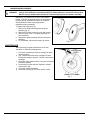
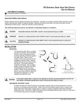
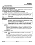
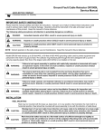
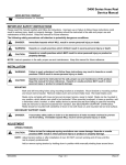
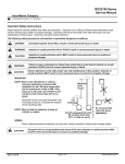
D8800 Hose Reel Series
Service Manual
Aero-Motive Company
A Woodhead Industries, Inc. Subsidiary
Important Safety Instructions
Please read this manual carefully and follow its instructions. Improper use or failure to follow these instructions could
result in serious injury, death or property damage. Operators should be instructed in the safe and proper use and
maintenance of this product. Keep this manual for future reference.
The following safety precautions call attention to potentially dangerous conditions.
DANGER:
Immediate hazards which WILL result in severe personal injury or death.
WARNING:
Hazards or unsafe practices which COULD result in severe personal injury or death.
CAUTION:
Hazards or unsafe practices which MAY result in minor personal injury or product or
property damage.
INSTALLATION
MOUNTING
(Fig. 1) The reel can be wall-, floor-, or ceiling
mounted according to the illustrations.
• Choose a way of mounting to avoid
excessive bending of the hose against the
outlet rollers.
• Select a level surface to mount the reel and
use the template to mark the holes.
• Ensure suitable fixing bolts are used and
they are secure.
• When choosing a mounting place it should
be noted the lifetime of the hose can be
affected by chemicals and strong UV- or
heat radiation.
Fig. 1
SECONDARY SUPPORT CHAIN
DANGER:
A secondary safety cable or chain is to be attached to all reels mounted overhead to prevent
reel from falling. Immediate hazards WILL result in severe personal injury or death.
All reels mounted over head should have a secondary support chain to protect personnel in case of
structure or mounting component failure. Attach one end of secondary support chain or cable to reel.
Attach other end of secondary support chain or cable to a support component other than that which
supports the reel. The chain or cable should be as short as possible allowing reel to drop no more than 6
to 12 inches if the primary connection is released.
SM514001E
Page 1 of 6
©Aero-Motive CompanyDec-03
SUPPLY HOSE
NOTE: A 90° female NPT elbow is included for
spool side hose connection (fig. 2).
Inlet connection is Male NPT and
requires a 90o elbow (by customer) on
inlet hose (fig. 3). An elbow with female
NPT connections on both ends will
allow a male NPT fitting on inlet hose.
(Fig. 2 & 3) The reel must be connected to
the pipework system with flexible inlet
hose only. [Do not use rigid pipe.]
The hose should go through the ring
connected to the bracket (see arrow)
before connecting to swivel. Check that
the inlet hose is not twisted or strained
after connection. Install reducer bushings
as necessary.
Fig. 2
A cut-off valve should be fitted on the pipe
system before the hose connection.
Fig 3
ADJUSTMENT
RATCHET LOCK
Ratchet lock is included on every model and works with reel mounted in any position. If application
requires constant tension instead, complete ratchet lock mechanism must be removed.
To remove ratchet lock:
1. Remove all reel tension.
2. Remove the plastic cover and spring hub (fig. 6).
3. Remove spool.
4. Remove ratchet and spring mechanism.
5. Reassemble reel.
HOSE GUIDE ARM POSITION
(Fig. 4) The guide arm may be rotated and
locked into multiple positions.
Select an angle to ensure a minimum bending
angle for the hose against the outlet rollers.
Fig. 4
SM514001E
Page 2 of 6
©Aero-Motive Company Dec-03
TENSION ADJUSTMENT
CAUTION:
Failure to test for adequate spring revolutions can cause damage. Hazards or unsafe
practices MAY result in minor personal injury or product or property damage.
NOTE: Pull full length of hose out to insure enough spring revolutions remain for complete operation.
Always leave at least 1-2 turns between full extension and when the spring is wound tight
(bottomed out). If entire hose assembly cannot be pulled out, decrease spring tension until full
extension is possible.
Reels shipped with hose installed are pre-tensioned at the factory. Reels shipped without hose require
pre-tensioning after hose is installed and before making final hose connections. To pre-tension hose
reel, pull hose out far enough to allow one full wrap of hose to be looped back over drum assembly (you
may have to remove the Hose Guide w/Ring). Prevent drum from turning and loop hose back on drum.
Repeat steps above until desired tension is achieved. After tension is set, pull hose out completely to
check spring travel. If full hose extension is not possible, remove pre-tension turns until full hose tension
is possible. Failure to test in this manner may cause spring damage. Complete all hose connections.
SERVICE
WARNING:
Before performing any service, always disconnect and lock out compressed air or fluid
media before attempting any service. Hazards or unsafe practices COULD result in severe
personal injury or death.
HOSE INSTALLATION AND REPLACEMENT
NOTE: (Fig. 2) A 90° female NPT elbow is included for
spool side connection with male NPT hose fitting.
Inlet connection is Male NPT and requires a 90o
elbow (by customer) on inlet hose (fig. 3). An
elbow with female NPT connections on both ends
will allow a male NPT fitting on inlet hose.
1. Turn off supply of input fluid media.
2. Pull out hose completely.
3. Engage the safety catch to the drum by disengaging
the safety loop (fig 5).
4. Remove ball stop from hose.
5. Disconnect hose from swivel.
6. Remove hose from reel.
7. Lay new hose on floor, pull end though guide and
attach to swivel.
8. Disengage safety catch and allow hose to slowly
rewind (fig. 5).
9. Engage ratchet and install hose stop.
10. Recheck connections and turn on the supply of fluid.
SWIVEL REPLACEMENT
1.
2.
3.
4.
5.
6.
7.
8.
Turn off supply of input fluid media.
Engage the safety loop (fig. 5).
Disconnect both input and output hose from swivel.
Remove swivel from reel.
Install new swivel.
Attach input and out hoses to swivel.
Disengage safety loop (fig. 5).
Recheck connections and turn on the supply of fluid
media.
(Refer to supply hose installation as needed.)
Fig. 5
NOTE: Install reducer bushing w/thread sealant when
necessary.
SM514001E
Page 3 of 6
©Aero-Motive Company Dec-03
MAINSPRING REPLACEMENT
WARNING:
Never, under any circumstances, remove spring from its container assembly. Replacement
springs are assembled in a sealed assembly for safety and there is no need to remove them.
Serious injury or death COULD result from removal of spring from its container assembly.
Mainspring is completely self-contained and safe to
handle. If reel will not develop tension or retract hose,
the main spring, assembly will need to be replaced.
See Replacement Parts for the appropriate
replacement spring assembly.
To replace main spring (fig. 6):
1. Remove four bolts connecting base to spring
assembly (fig. 4).
2. Remove six screws to housing cover and remove.
3. Remove screw in hub. Pull spring assembly off
drum assembly.
4. Replace the spring assembly with the new spring
assembly.
5. To reassemble, follow this procedure in reverse.
Fig. 6
MAINTENANCE
When performing regular maintenance on the reel,
remember to check the following items:
1. Check the mainspring function by testing if the hose
retracts properly.
2. (Fig. 7)Check swivel and hose couplings for leaks.
Change the seal(s) if required. Clean the swivel and
couplings.
3. Check the reel’s external seals. If any are cracked, all
should be replaced.
4. Check hose for wear and tear. Replace if needed.
Clean hose if dirty.
5. Check the ratchet mechanism.
6. Check the mounting of the reel on wall or ceiling.
Fig. 7
SM514001E
Page 4 of 6
©Aero-Motive Company Dec-03
REPLACEMENT PARTS
SM514001E
Page 5 of 6
©Aero-Motive Company Dec-03
Reference
Number *
1
2
4
5
7
8
9
11
14
15
19
23
Part Number
H42330559
H22120030
H22710022
H25410118
M04820001
M11100002
H41220149
H41220150
H41220156
H46230020
H72320053
H72320054
H72320055
H73130043
H33340010
H33340011
H33340012
H33340013
H33340014
H25410120
Daniel Woodhead Company
A Woodhead Industries Inc. Subsidiary
Northbrook, IL USA
888-996-6343 Fax: (847) 272-8133
www.danielwoodhead.com
Qty.
1
1
1
1
1
1
1
1
1
1
1
1
Description
Drum/Insert
Bracket/Clamp/Fasteners
Cover w/Seal
Hose Guide w/Ring
Spring Hub w/Fasteners
Bearing
Spring Assembly with Outlet Arm/Bushing; D8814
Spring Assembly with Outlet Arm/Bushing; D8824
Spring Assembly with Outlet Arm/Bushing; D8816 & D8818
Ratchet kit
Swivel Assembly; 1/2”
Swivel Assembly; 3/4”
Swivel Assembly; 1”
Seal and Backing Washer for all size swivels
Hose Stop; 1/4”
Hose Stop; 3/8”
Hose Stop; 1/2”
Hose Stop; 3/4”
Hose Stop; 1”
Outlet, complete with Rollers
Woodhead Canada LTD.
Aero-Motive Company
A Woodhead Industries Inc. Subsidiary
A Woodhead Industries Inc. Subsidiary
Mississauga Ontario Canada
(905) 624-1079 FAX: (905) 624-9151
www.woodhead.ca
[email protected]
SM514001E
Page 6 of 6
Kalamazoo, MI USA
(269) 337-7700 FAX: (800) 333 6119
www.aeromotive.com
[email protected]
©Aero-Motive Company Dec-03