1
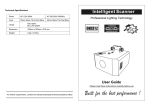
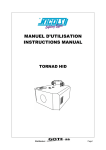
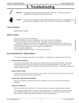
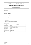
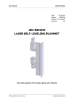
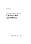
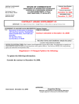
SBC Series
Half Size 4-slots Chassis
FA-UNIT-H4BE
User’s Manual
CONTEC CO.,LTD.
Check Your Package
Thank you for purchasing the CONTEC product.
The product consists of the items listed below.
Check, with the following list, that your package is complete.
items, contact your retailer.
If you discover damaged or missing
Product Configuration List < FA-UNIT-H4BE >
- Chassis [FA-UNIT-H4BE] …1
- Power cable …1
- IDE signal conversion cable *1 …1
- Rubber pads …4
- Screws (for Rubber pads) (M4 x 8) …4
- Screws (used for HDD and board installation) (M3 x 6) …14
- Hexagon spacer …6
- Bracket for wall-mounted …2
- Slot cover …4
- User’s Manual …1
*1: It corresponds to ATA33
x4
Rubber pads
x 14
x4
Screws
Screws (used for HDD
(for Rubber pads) and board installation)
Chassis
Power cable
User’s Manual
x6
Hexagon spacer
x4
Slot cover
IDE signal
conversion cable
x2
User’s Manual
FA-UNIT-H4BE
Bracket for wall-mounted
i
Copyright
Copyright 2005 CONTEC CO., LTD. ALL RIGHTS RESERVED
No part of this document may be copied or reproduced in any form by any means without prior written
consent of CONTEC CO., LTD.
CONTEC CO., LTD. makes no commitment to update or keep current the information contained in this
document. The information in this document is subject to change without notice.
All relevant issues have been considered in the preparation of this document. Should you notice an
omission or any questionable item in this document, please feel free to notify CONTEC CO., LTD.
Regardless of the foregoing statement, CONTEC assumes no responsibility for any errors that may
appear in this document or for results obtained by the user as a result of using this product.
Trademarks
Other brand and product names are trademarks of their respective holder
ii
FA-UNIT-H4BE
Table of Contents
Check Your Package ................................................................................................................................ i
Copyright .................................................................................................................................................ii
Trademarks ..............................................................................................................................................ii
Table of Contents ...................................................................................................................................iii
1.
BEFORE USING THE PRODUCT
1
About the Chassis.................................................................................................................................... 1
Features............................................................................................................................................. 1
Configuration ................................................................................................................................... 1
Option ............................................................................................................................................... 2
Available Replaceable Parts for Maintenance ................................................................................ 2
Customer Support.................................................................................................................................... 3
Web Site ........................................................................................................................................... 3
Limited One-Year Warranty ................................................................................................................... 3
How to Obtain Service............................................................................................................................ 3
Liability ................................................................................................................................................... 3
Safety Precautions ................................................................................................................................... 4
Safety Information ........................................................................................................................... 4
Handling Precautions ....................................................................................................................... 5
Environment ..................................................................................................................................... 6
Inspection ......................................................................................................................................... 6
Storage.............................................................................................................................................. 6
Disposal ............................................................................................................................................ 6
2.
NAME OF EACH PART AND DIMENSIONS DIAGRAM
7
Parts of the Chassis ................................................................................................................................. 7
Front Side View ............................................................................................................................... 7
Rear Side View................................................................................................................................. 7
Dimensions .............................................................................................................................................. 8
Positions of backplane installation holes ...................................................................................... 10
3.
INSTALLING THE BACKPLANE
11
Installing the backplane ........................................................................................................................ 11
Preparation...................................................................................................................................... 11
To install the backplane ................................................................................................................. 11
Installing an expansion board ............................................................................................................... 13
Preparation...................................................................................................................................... 13
To install the backplane ................................................................................................................. 13
Unplugging an Expansion Board................................................................................................... 14
FA-UNIT-H4BE
iii
Installing Disk Drives............................................................................................................................15
Preparation ......................................................................................................................................15
Installing the disk drive ..................................................................................................................15
Installing/Removing a fan and filter .....................................................................................................16
Installing PC-DBU2 ..............................................................................................................................17
Preparation ......................................................................................................................................17
Installing the disk drive ..................................................................................................................17
Installation conditions ...........................................................................................................................19
Installing the wall mount bracket..........................................................................................................20
4.
CONNECTORS
21
Power Supply .........................................................................................................................................21
Backplane power supply connectors..............................................................................................21
HDD/FDD power supply connectors.............................................................................................21
Switches and LEDs................................................................................................................................22
5.
SYSTEM REFERENCE
23
Specification ..........................................................................................................................................23
iv
FA-UNIT-H4BE
1. Before Using the Product
1. Before Using the Product
This chapter provides information you should know before using the product.
About the Chassis
FA-UNIT-H4BE is a chassis used to mount a backplane and SBC and configure a computer system in
combination with expansion boards and various drives.
Features
-
PCI or ISA bus backplane can be mounted
-
Equipped with 2.5-inch drive bay x 1(shadow bay)
-
Equipped with a built-in cooling fan. The dustproof filter and cooling fan can be replaced externally
These fans can easily be replaced externally, without removing the top cover.
-
A chassis fixing bracket is attached as standard.
Configuration
Backplanes is sold separately. You need prepare a CONTEC backplane corresponding to this product,
separately. For more details of the corresponding backplanes, see "Option".
When using a backplane, pay attention to the positions of the backplane installation holes, installable
size, and power supply specifications of this product.
FA-UNIT-H4BE
1
1. Before Using the Product
Option
Installable backplanes
-
BPC-0411
PCI Backplane with 3-Slots (PCI x 3)
-
BPS-0411
ISA Backplane with 4-Slots (ISA x 4)
Drive bay unit
-
PC-DBU2
Drive bay unit (5-inch drive x 1)
Other
-
FA-CLAMP-01
Clamp for PCI/ISA board (5 pcs)
*
Check the CONTEC’s Web site for more information on these options.
Available Replaceable Parts for Maintenance
-
POW251X
300W IU type ATX Power Supply
-
FAN0925S
Fan 90 x 25 with Sensor
-
FLT93
Fan Filter (95 x 95)
2
FA-UNIT-H4BE
1. Before Using the Product
Customer Support
CONTEC provides the following support services for you to use CONTEC products more efficiently
and comfortably.
Web Site
Japanese
English
Chinese
http://www.contec.co.jp/
http://www.contec.com/
http://www.contec.com.cn/
Latest product information
CONTEC provides up-to-date information on products.
CONTEC also provides product manuals and various technical documents in the PDF.
Free download
You can download updated driver software and differential files as well as sample programs available in
several languages.
Note!
For product information
Contact your retailer if you have any technical question about a CONTEC product or need its price,
delivery time, or estimate information.
Limited One-Year Warranty
CONTEC products are warranted by CONTEC CO., LTD. to be free from defects in material and
workmanship for up to one year from the date of purchase by the original purchaser.
Repair will be free of charge only when this device is returned freight prepaid with a copy of the
original invoice and a Return Merchandise Authorization to the distributor or the CONTEC group office,
from which it was purchased.
This warranty is not applicable for scratches or normal wear, but only for the electronic circuitry and
original products. The warranty is not applicable if the device has been tampered with or damaged
through abuse, mistreatment, neglect, or unreasonable use, or if the original invoice is not included, in
which case repairs will be considered beyond the warranty policy.
How to Obtain Service
For replacement or repair, return the device freight prepaid, with a copy of the original invoice. Please
obtain a Return Merchandise Authorization number (RMA) from the CONTEC group office where you
purchased before returning any product.
*
No product will be accepted by CONTEC group without the RMA number.
Liability
The obligation of the warrantor is solely to repair or replace the product. In no event will the warrantor
be liable for any incidental or consequential damages due to such defect or consequences that arise from
inexperienced usage, misuse, or malfunction of this device.
FA-UNIT-H4BE
3
1. Before Using the Product
Safety Precautions
Understand the following definitions and precautions to use the product safely.
Safety Information
This document provides safety information using the following symbols to prevent accidents resulting in
injury or death and the destruction of equipment and resources. Understand the meanings of these
labels to operate the equipment safely.
DANGER
DANGER indicates an imminently hazardous situation which, if not avoided, will
result in death or serious injury.
WARNING
WARNING indicates a potentially hazardous situation which, if not avoided, could
result in death or serious injury.
CAUTION
CAUTION indicates a potentially hazardous situation which, if not avoided, may
result in minor or moderate injury or in property damage.
FCC PART 15 Class A Notice
NOTE
This equipment has been tested and found to comply with the limits for a Class A digital device,
pursuant to part 15 of the FCC Rules. These limits are designed to provide reasonable protection
against harmful interference when the equipment is operated in commercial environment.
This equipment generates, uses, and can radiate radio frequency energy and, if not installed and
used in accordance with the instruction manual, may cause harmful interference to radio
communications. Operation of this equipment in a residential area is likely to cause harmful
interference at his own expense.
WARNING TO USER
Change or modifications not expressly approved the manufacturer can void the user's authority to
operate this equipment.
4
FA-UNIT-H4BE
1. Before Using the Product
Handling Precautions
CAUTION
-
If you turn the power switch off, wait for at least five seconds before turning it on again.
-
When plugging or unplugging the power cable, be sure to hold the plug itself.
-
Since the product is a precision device, do not use or store it where it is subject to shock or vibration.
Also avoid any place where the unit is exposed to direct sunlight, extremely high or low humidity,
or much dust.
-
Do not use or store this product where it is exposed to any chemical directly or as vapor in the air.
-
This product has ventilating slits to prevent it from being heated excessively.
with the ventilating slits blocked or in an ill-ventilated place.
-
Do not use this product near equipment generating a strong magnetic field or noise, or the field or
noise may cause this product or personal computer to malfunction.
-
It is very dangerous to use this product with water, liquid, or metal (conductive) chips left inside.
Be careful not to let such foreign matters in this product.
-
When installing or removing an interface board into/from an expansion slot, be sure to remove the
cable from the AC inlet.
-
The total power consumption by the boards installed in expansion slots must not exceed the rating.
-
If the product becomes dirty, wipe it carefully with a soft cloth damped with water or a solution of
neutral detergent. Keep in mind that using a volatile solvent, such as benzine or thinner, or a
chemical can deform or discolor the surface of this product.
-
When performing maintenance of boards and electrical system components, be sure to remove the
cable from the AC inlet.
-
The installable power supply is one that can be used in industrial environments where spike voltage
of 1.5kV or so is generated. If spike overvoltage higher than this voltage is generated, protective
actions may be required.
-
The specifications of this product are subject to change without notice for enhancement and quality
improvement.
Even when using the product continuously, be sure to read the manual and understand the contents.
-
Do not modify the product. CONTEC will bear no responsibility for any problems, etc., resulting
from modifying this product.
-
Regardless of the foregoing statements, CONTEC is not liable for any damages whatsoever
(including damages for loss of business profits) arising out of the use or inability to use this
CONTEC product or the information contained herein.
FA-UNIT-H4BE
Avoid using the unit
5
1. Before Using the Product
Environment
Use this product in the following environment.
overheat, malfunction, or cause a failure.
If used in an unauthorized environment, the board may
Operating temperature
0 - 50°C
Operating humidity
10 - 80%RH (No condensation)
Corrosive gases
None
Floating dust particles
Not to be excessive
Inspection
Inspect the product periodically as follows to use it safely.
- Ventilating slits must neither be blocked nor have
dust or foreign matters adhering.
Front side view
Rear side view
Storage
When storing this product, keep it in its original packing form.
(1) Put this product in the storage bag.
(2) Store the package at room temperature at a place free from direct sunlight, moisture, shock,
vibration, magnetism, and static electricity.
Disposal
When disposing of the product, follow the disposal procedures stipulated under the relevant laws and
municipal ordinances.
6
FA-UNIT-H4BE
2. Name of Each Part and Dimensions Diagram
2. Name of Each Part and Dimensions Diagram
Parts of the Chassis
Front Side View
Power LED Power SW
HDD access LED Reset SW
Figure 2.1.
Front Side View
Rear Side View
Fan replacement hatch
Figure 2.2.
Rear Side View
FA-UNIT-H4BE
7
2. Name of Each Part and Dimensions Diagram
Dimensions
4-φ5
105
250
170
105
204
188
172
177
15
R2.5
R4.5
RESE T
10
[mm]
Figure 2.3.
8
Dimensions < Horizontally placed >
FA-UNIT-H4BE
193
209
2. Name of Each Part and Dimensions Diagram
R4.5
R2.5
15
105
170
105
4-φ5
250
177
10
172
RES ET
[mm]
Figure 2.4.
Dimensions < Vertically placed >
FA-UNIT-H4BE
9
2. Name of Each Part and Dimensions Diagram
Positions of backplane installation holes
14.38
78.6
53.2
6-M3
139.7
158.6 Max.
15.875
15.24
45.26
20.62
25.4 Max.
12.7
[mm]
3.81 Max.
Figure 2.5.
10
102.17 Max.
Positions of backplane installation holes
FA-UNIT-H4BE
3. Installing the Backplane
3. Installing the Backplane
Installing the backplane
There are various types of backplanes and their installation hole positions are all different.
basically any of them can be installed by following the same procedures.
However,
Preparation
(1) Turn the power switch off.
(2) Pull the power plug of the unit from the wall outlet.
To install the backplane
(1) Remove the screws fastening the top cover, then remove the cover.
use the appropriate type of screwdriver that fits the screw head.
When loosening the screws,
(2) Remove the fall-off prevention bar and 2.5-inch drive bay from the expansion board.
FA-UNIT-H4BE
11
3. Installing the Backplane
(3) Next, fix the attached hexagon spacers to the holes in the main unit and place the backplane on it
and fix it with screws.
(4) Return the fall-off prevention bar and cover to their original positions and fix them with screws.
12
FA-UNIT-H4BE
3. Installing the Backplane
Installing an expansion board
Various types of boards can be installed in the expansion slot.
following the same procedures.
However, any of them can be installed
Preparation
(1) Turn the power switch off.
(2) Pull the power plug of the unit from the wall outlet.
To install the backplane
(1) Remove the screws fastening the top cover, then remove the cover.
use the appropriate type of screwdriver that fits the screw head.
When loosening the screws,
(2) Remove the fall-off prevention bar and 2.5-inch drive bay from the expansion board.
FA-UNIT-H4BE
13
3. Installing the Backplane
(3) Install the expansion board and fix it with screws.
(4) Return the fall-off prevention bar and cover to their original positions and fix them with screws.
Unplugging an Expansion Board
To unplug an expansion board, follow the steps below in the reverse order of plugging it.
(1) Before starting removing the expansion board, pull the power plug of the unit from the wall outlet.
(2) Following the same procedures as for insertion, remove the bracket fixing screws of the slot from
which you want to remove the board.
(3) Remove the board by pulling it at a right angle to the expansion slot.
(4) Use the screw to fasten the bracket removed when plugging the board.
(5) Replace and screw the cover.
14
FA-UNIT-H4BE
3. Installing the Backplane
Installing Disk Drives
FA-UNIT-H4BE can have one 2.5-inch drives built in it.
Preparation
(1) Turn the power switch off.
(2) Pull the power plug of the unit from the wall outlet.
Installing the disk drive
(1) Remove the screws fastening the top cover, then remove the cover.
use the appropriate type of screwdriver that fits the screw head.
When loosening the screws,
(2) Remove the fall-off prevention bar and 2.5-inch drive bay from the expansion board.
FA-UNIT-H4BE
15
3. Installing the Backplane
(3) Attach the drive to the 2.5-inch drive bay.
Connect the cables and fix them to the original position of the chassis.
Connect the 2.5 inch drive with the SBC using the supplied cable (IDE signal conversion cable).
(4) Return the fall-off prevention bar and cover to their original positions and fix them with screws.
Installing/Removing a fan and filter
You can install/remove a fan and filter, without removing the top cover.
Relay connector
Finger guard
FAN
Filter
FAN cover
* The installation of the fan is obtained in the reverse order of removing.
Figure 3.1.
16
Installing/Removing a fan and filter
FA-UNIT-H4BE
3. Installing the Backplane
Installing PC-DBU2
Installing the optional drive bay unit [PC-DBU2] enables the FA-UNIT-H4BE to install one 5-inch
drive.
Preparation
(1) Turn the power switch off.
(2) Pull the power plug of the unit from the wall outlet.
Installing the disk drive
(1) Remove the screws fastening the top cover, then remove the cover.
use the appropriate type of screwdriver that fits the screw head.
When loosening the screws,
(2) Remove the fall-off prevention bar and 2.5-inch drive bay from the expansion board.
FA-UNIT-H4BE
17
3. Installing the Backplane
(3) Remove the cover for cable hole on the side panel of the chassis and mount the flexible bush
(provided with the PC-DBU2) for cable protection.
(4) Install the PC-DBU2 and the 5 inch drive as illustrated and connect the cables.
Fix the cover removed at step (3) on the rear panel of the PC-DBU2 to prevent losing it.
(5) Return the fall-off prevention bar, 2.5-inch drive bay and cover to their original positions and fix
them with screws.
18
FA-UNIT-H4BE
3. Installing the Backplane
Installation conditions
50
To prevent a temperature rise, install this chassis at a distance of at least 50mm from obstacles such as
walls.
50
50
50
50
[mm]
Figure 3.2.
Installation conditions
FA-UNIT-H4BE
19
3. Installing the Backplane
Installing the wall mount bracket
Installing the attached bracket enables wall mount.
The bracket can be installed in two ways. Install the bracket using an appropriate method in accordance
with the use environment.
< Horizontal >
Figure 3.3.
20
< Vertical >
Installing the wall mount bracket
FA-UNIT-H4BE
4. Connectors
4. Connectors
Power Supply
This product has built-in power supply units. The backplane power supply connector and HDD and
FDD power supply connectors are provided. Connecting these connectors enables the motherboard and
HDD to operate.
Backplane power supply connectors
It connects it with Backplane.
Pin No.
Function
Pin No.
Function
1
+3.3V
11
2
+3.3V
12
-12V
3
COM
13
COM
4
+5V
14
ON/OFF
5
COM
15
COM
6
+5V
16
COM
7
COM
17
COM
8
P.G
18
-5V
9
+5VS
19
+5V
10
+12V
20
+5V
Figure 4.1.
+3.3V
Backplane power supply connectors
HDD/FDD power supply connectors
YELLOW
BLACK
BLACK
RED
1. 12V
2. GND
3. GND
4. +5V
YELLOW
BLACK
BLACK
RED
1. 12V
2. GND
3. GND
4. +5V
Figure 4.2.
To HDD or CD-ROM
To 3.5 inch FDD
(nonuse)
HDD/FDD power supply connectors
FA-UNIT-H4BE
21
4. Connectors
Switches and LEDs
This product has two switches and two LEDs at the front.
One of the switches is the power switch for turning the power supply on and off.
(POWER) comes on when you turn the power on.
The second switch is the reset switch for rebooting the system.
The red LED (HDD) indicates the access status of the hard disk drive.
The green LED
These switches and LEDs operate with their respective connector cables connected to the corresponding
connectors on the SBC(CPU board).
(1)Power SW
White
Black
(2)Power LED
Green(+)
Black
(3)HDD LED
Red (+)
Black
(4)Reset SW
Yellow
Black
Figure 4.3.
22
Switch and LED Connector Cables
FA-UNIT-H4BE
5. System Reference
5. System Reference
Specification
Table 5.1.
General specifications
Item
Number of user slots
Installable board (mm)
Specification
4 half-size slot
185.0(L) x 122.0(H) (Max.)
(See "Dimensions of installable board" for detail.)
Rack mountable
Impropriety
Fan
Inlet x 1 (Excluding power supply fan)
Drive bay
2.5-inch x 1 (shadow bay) *1*2
Option drive bay [PC-DBU2](5-inch x 1) installable
Number of slot holes
4
Installable Backplane dimensions 106.0(W) x 184.0(D) (Max.) (For details see "Figure 2.5".)
(mm)
BPC-0411, BPS-0411
Dimensions (mm)
172(W) x 250(D) x 177(H) (Excluding raised parts)
Weight
About 5kg (Excluding backplane, drives, etc.)
*1:
Only HDD can be mounted on the shadow bay (FDD cannot be mounted).
*2:
The bundled IDE signal conversion cable is capable of corresponding to ATA33.
Table 5.2.
Power supply specifications
Item
Power capacity *3
Overall maximum
Specification
+5V
15A
+3.3V 14A
-12V
+12V
+5VSB 2A
11A
0.8A
250W
power supply capacity
AC Power Voltage
90 - 264VAC(47 - 63Hz) Continuous input
Input current
4.5A (Max.)
AC Outlet
None
*3:
Total of +5V and +3V shall not exceed the power of 110W.
FA-UNIT-H4BE
23
5. System Reference
Table 5.3.
Environmental specification
Item
Specification
Operating temperature
0 - 50°C
Operating humidity
10 - 80%RH (No condensation)
Storage temperature
0 - 60°C
Storage humidity
10 - 90%RH (No condensation)
Vibration resistance
10 - 57Hz/semi-amplitude 0.075mm, 57 - 150Hz/1.0G
Impact resistance
10G half-sine shock for 11ms
Floating dust particles
Not to be excessive
Corrosive gases
None
* The values in the above are constrained with the boards or the components such as drives installed inside the product,
so the figures do not necessarily represent the tolerances for every operating condition.
Dimensions of installable board (Max.)
122.0(H)
185.0(L)
[mm]
CAUTION
The internal power supply and cooling fan, fan filter are consumables, requiring replacement after
use for a certain period of time.
Although the standards are given below, their lives may be shortened depending on the operating
environment. The life span is likely especially to become short extremely in the place which takes
influence of trash, metallic powder, the place which is much dust or oil, corrosive gas.
24
- Power supply
:
About 5 years (25°C, 60%, 75% load, official environment)
- Cooling Fan
:
About 5 years (25°C, 60%, official environment)
- Fan filter
:
About 1 year (25°C, 60%, official environment)
FA-UNIT-H4BE
FA-UNIT-H4BE
User’s Manual
CONTEC CO., LTD.
November 2006 Edition
3-9-31, Himesato, Nishiyodogawa-ku, Osaka 555-0025, Japan
Japanese http://www.contec.co.jp/
English http://www.contec.com/
Chinese http://www.contec.com.cn/
No part of this document may be copied or reproduced in any form by any means without prior written
consent of CONTEC CO., LTD.
[11022006]
[12052005]
[11022006_rev4]
Management No.
Parts No.
A-51-093
LYFJ323