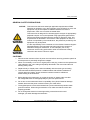
1
NOTICE: This document contains references to Varian. Please note that Varian, Inc. is now part of Agilent Technologies. For more information, go to www.agilent.com/chem. Varian BV Herculesweg 8 4330 EA Middelburg The Netherlands Micro-GC PRO Extension Boards User Manual North/South America 2700 Mitchell Drive Walnut Creek 94598 California, USA Tel: ++(1)9259392400 Fax: ++(1)9259452360 or ++(1)9259452344 © 2009 Varian, Inc. All Rights Reserved Europe P.O. Boards 8033 4330 EA Middelburg The Netherlands Tel: ++(31)118671000 Fax: ++(31)118623193 Printed in the Netherlands Australia/East Asia 679 Springvale Road Mulgrave, Victoria 3171 Australia Tel: ++(61)395607133 Fax: ++(61)395607950 CP501370 Rev:3 November 2009 Safety information VARIAN ANALYTICAL INSTRUMENT WARRANTY HARDWARE PRODUCTS All analytical instruments sold by Varian are warranted to be free from defects in material and workmanship for the periods specified and in accordance with the terms on the face of Varian's quotation or as otherwise agreed upon in writing between Varian and the Customer. The warranty period begins on the date of shipment from Varian to the original Customer. However, where installation is paid for by the Customer or included in the purchase price, the warranty period begins upon completion of installation. If the Customer schedules installation to start later than 30 days after delivery or if such delay is caused through the Customer's inability to provide adequate facilities or utilities or through failure to comply with Varian's reasonable pre-installation instructions or through other omissions by Customer, then the warranty period starts on the 31st day from date of shipment. Moreover Varian will charge the Customer for labor and other expenses involved in making multiple or follow-up installation service calls. SOFTWARE PRODUCTS Where software is provided within the frame of a license agreement concluded between the Customer and Varian, any warranty shall be strictly in accordance with the terms of such agreement. In the absence of a license agreement and unless an alternate warranty period is agreed upon in writing between Varian and the Customer, the warranty period is as specified on the face of Varian's quotation. Varian warrants such software products, if used with and properly installed on Varian hardware or other hardware as specified by Varian to perform as described in the accompanying Operator's Manual and to be substantially free of those defects which cause failure to execute respective programming instructions; however, Varian does not warrant uninterrupted or error-free operation. REMEDIES The sole and exclusive remedy under hardware warranty shall be repair of instrument malfunctions which in Varian's opinion are due or traceable to defects in original materials or workmanship or, at Varian's option, replacement of the respective defective parts, provided that Varian may as an alternative elect to refund an equitable portion of the purchase price of the instrument or accessory. Repair or replacement under warranty does not extend the original warranty period. Repair or replacement under warranty claims shall be made in Varian's sole discretion either by sending a Customer Support Representative to the site or by authorizing the Customer to return the defective accessory or instrument to Varian or to send it to a designated service facility. The Customer shall be responsible for loss or damage in transit and shall prepay shipping cost. Varian will return the accessory or instrument to the Customer prepaid and insured. Claims for loss or damage in transit shall be filed by the Customer. To correct software operation anomalies, Varian will issue software revisions where such revisions exist and where, in Varian's opinion, this is the most efficient remedy. LIMITATION OF WARRANTY This warranty does not cover software supplied by the Customer, equipment and software warranted by another manufacturer or replacement of expendable items and those of limited life, such as but not limited to: Filters, glassware, instrument status lamps, source lamps, septa, columns, fuses, chart paper and ink, nebulizers, flow cells, pistons, seals, fittings, valves, burners, sample tubes, probe inserts, print heads, glass lined tubing, pipe and tube fittings, variable temperature dewars, transfer lines, flexible discs, magnetic tape cassettes, electron multipliers, filaments, vacuum gaskets, seats and all parts exposed to samples and mobile phases. This warranty shall be void in the event of accident, abuse, alteration, misuse, neglect, breakage, improper operation or maintenance, unauthorized or improper modifications or tampering, use in an unsuitable physical environment, use with a marginal power supply or use with other inadequate facilities or utilities. Reasonable care must be used to avoid hazards. This warranty is expressly in lieu of and excludes all other express or implied warranties, including but not limited to warranties of merchantability and of fitness for particular purpose, use or application, and all other obligations or liabilities on the part of Varian, unless such other warranties, obligations or liabilities are expressly agreed to in writing by Varian. LIMITATION OF REMEDIES AND LIABILITY The remedies provided herein are the sole and exclusive remedies of the Customer. In no case will Varian be liable for incidental or consequential damages, loss of use, loss of production or any other loss incurred. Page II User Manual Micro-GC Extension Boards Varian, Inc. Safety Information SAFETY INFORMATION INFORMATION In accordance with Varian’s commitment to customer service and safety, this Micro-GC PRO Extension Boards and its accompanying documentation (NEN 5509) complies with the CE specifications and the safety requirements for electrical equipment for measurement, control, and laboratory use (CEI/IEC 1010-1). This device has been tested and found to comply with the limits for a Class A digital device, pursuant to part 15 of the FCC rules. These limits are designed to provide reasonable protection against harmful interference when the equipment is operated in a commercial environment. This equipment generates, uses, and can radiate radio frequency energy and, if not installed and used in accordance with the instruction manual, may cause harmful interference to radio communications. Operation of this equipment in a residential area is likely to case harmful interference in witch case the user will be required to correct the interference at his own expense. To prevent any injury to the user or any damage to the instrument it is essential that you read the information in this chapter. If this manual is not in your native language and if you have problems understanding the text, we advise you to contact your Varian office for assistance. Varian cannot accept responsibility for any damage or injury caused by misunderstanding of the information in this manual. OPERATING INSTRUCTIONS This instruction manual is provided to help you establish operating conditions, which will permit safe and efficient use of your equipment. Special considerations and precautions are also described in the manual, which appear in the form of NOTES, CAUTIONS, and WARNINGS as described below (next page). It is important that you operate your equipment in accordance with this instruction manual and any additional information, which may be provided by Varian. Address any questions regarding the safe and proper use of your equipment to your local Varian office. Varian, Inc. User Manual Micro-GC Extension Boards Page III Safety information NOTE Information to aid you in obtaining optimal performance from your instrument. CAUTION Alerts you to situations that may cause moderate injury and/or equipment damage, and how to avoid these situations. Warning Symbol Warning Description WARNING: Shock hazard Indicates dangerous voltage: (terminals fed from the interior by voltage exceeding 1000V must be so marked.) WARNING: Burn hazard Indicates parts that may cause burns when touched Instruction Manual Indicates that the user should refer to the manual before operating the equipment. Protective Conductor terminal For protection against electrical shock in case of a fault. Used with field wiring terminals to indicate the terminal, which must be connected to ground before operating equipment. Radioactive hazard Indicates that the instrument contains radioactive components, which may cause personal injury when handled incorrectly. Skin puncture Static discharge Warning Do not touch Page IV WARNING Alerts you to potentially hazardous situations that could result in serious injury, and how to avoid these situations. Indicates sharp or suddenly moving parts such as injection needles that may cause injury. Indicates instrument contains parts that can be damaged by electrostatic discharge. Take care for proper grounding before handling. Touching this item may result in damage to the instrument or personal injury. User Manual Micro-GC Extension Boards Varian, Inc. Safety Information GENERAL SAFETY PRECAUTIONS NOTICE: This instrument has been tested per applicable requirements of EMC Directive as required to carry the European Union CE Mark. As such, this equipment may be susceptible to radiation/interference levels or frequencies, which are not within the tested limits. This instrument is designed for chromatographic analysis of appropriately prepared samples. It must be operated using appropriate gases and/or solvents and within specified maximum ranges for pressure, flows, and temperatures as described in this manual. If the equipment is used in a manner not specified by the manufacturer, the protection provided by the equipment may be impaired. It is the responsibility of the Customer to inform Varian Customer Support Representatives if the instrument has been used for the analysis of hazardous biological, radioactive, or toxic samples, prior to any instrument service being performed or when an instrument is being returned to the Service Center for repair. CAUTIONS 1. Disconnect the instrument from all power sources before removing protective panels to avoid exposure to potentially dangerous voltages. 2. When it is necessary to use a non-original power cord plug, make sure the replacement cord adheres to the color-coding and polarity described in the manual and all local building safety codes. 3. Replace faulty or frayed power cords immediately with the same type and rating. 4. This instrument should be placed in a suitable location with sufficient ventilation to remove gases and vapors. Space around the instrument must be sufficient to enable cooling of the instrument. 5. Before plugging the instrument in or turning the power on, always make sure that the voltage and fuses are set appropriately for your local power source. 6. Do not turn on the instrument if there is a possibility of any kind of electrical damage. Instead, disconnect the power cord and contact your Varian office. 7. The supplied power cord must be inserted into a power outlet with a protective earth ground connection. When using an extension cord, make sure that the cord is also properly grounded. 8. Do not change the external or internal grounding connections as this could endanger you and/or damage the instrument. Varian, Inc. User Manual Micro-GC Extension Boards Page V Safety information 9. The instrument is properly grounded when shipped. You do not need to make any changes to the electrical connections or to the instrument chassis to ensure safe operation. 10. When working with this instrument, follow the regulations for GLP (Good Laboratory Practice). Take care to wear safety glasses and appropriate clothing. 11. Do not place containers with flammable liquids on this instrument. Spillage of the liquid over hot parts may cause fire. 12. Never try to repair or replace any component that is not described in this manual without the assistance of a Varian service engineer. Unauthorized repairs or modifications will result in rejection of warranty claims. 13. Always disconnect the (AC) power cord before attempting any type of maintenance. 14. Use proper tools when working on the instrument to prevent danger for you and/or damage to the instrument. 15. The customer should not attempt to replace any fuses in this instrument. 16. Damage can result if the instrument is stored under unfavorable conditions for prolonged periods (e.g. subject to heat, water, etc.). 17. This unit has been designed and tested in accordance with recognized safety standards and designed for indoors use only. 18. If the Extension Boards is used in a manner not specified by the manufacturer, the protection provided by the instrument may be impaired. 19. Substituting parts or performing any unauthorized modification to the instrument may result in a safety hazard. 20. Changes or modifications not expressly approved by the responsible party for compliance could void the user’s authority to operate the equipment. Page VI User Manual Micro-GC Extension Boards Varian, Inc. Safety Information SPARE PARTS AVAILABILITY It is the policy of Varian to provide operational spare parts for any instrument and major accessory for a period of five (5) years after shipment of the final production run of that instrument. Spare parts will be available after this five (5) year period but on an as available basis. Operational spare parts are defined as those individual electrical or mechanical parts that are susceptible to failure during their normal operation. Examples include relays, lamps, temperature probes, detector elements, motors, etc. Sheet metal parts, structural members or assemblies and castings, printed circuit boards, and functional modules are normally capable of being rebuilt to like-new condition throughout their useful life and therefore will be supplied only on an as available basis after the final production run of the instrument. SERVICE AVAILABILITY Varian provides a variety of services to support its customers after warranty expiration. Repair service can be provided by attractively priced service contracts or on a time and material basis. Technical support and training can be provided by qualified personnel on both a contractual or asneeded basis. Varian Analytical Instruments Sales Offices For Sales or Service assistance and to order Parts and Supplies, contact your local Varian office. Argentina Buenos Aires Tel. +54.11.4.783.5306 France Les Ulis Cédex Tel. +33.1.6986.3838 Russian Federation Moscow Tel. +7.095.937.4280 Australia Mulgrave, Victoria Tel. +61. 3.9560.7133 Germany Darmstadt Tel. +49.6151.7030 Spain Madrid Tel. +34.91.472.7612 Austria Poettelsdorf Tel. +43.2626.20090 India Mumbai Tel. +91.22.2570.8595/97 Sweden Solna Tel. +46.8.445.1620 Benelux Middelburg Tel. +31.118.671500 Brazil and Latin America (S) São Paulo Tel. +55.11.32380400 Canada Mississauga, Ontario Tel. 800.387.2216 China Beijing Tel. +86.106310.8550 Europe Middelburg, The Netherlands Tel. +31.118.671.000 Varian, Inc. Italy Torino Tel. +39.011.997.9111 Japan Tokyo Tel. +81.3.5232.1239 Korea Seoul Tel. +82.333.665.5171 Mexico and Latin America (N) Mexico City Tel. +52.5.55.5239465/026 United States Walnut Creek, California, USA Tel. +1.800.926.3000 (GC and GC/MS) Tel. +1.800.367.4752 (LC) Switzerland Steinhausen Tel. +41.848.803.800 Taiwan Shih-Chi Tel. +886.22.698.9555 United Kingdom and Ireland Oxford Tel. +44.1865.291500 http://www.varianinc.com/ Venezuela Caracas Tel. +58.212.285.0320/2494 User Manual Micro-GC Extension Boards Page VII Table of contents TABLE OF CONTENTS VARIAN ANALYTICAL INSTRUMENT WARRANTY.................................................................. II HARDWARE PRODUCTS ................................................................................................................ II SOFTWARE PRODUCTS ................................................................................................................. II REMEDIES ................................................................................................................................... II LIMITATION OF WARRANTY ........................................................................................................... II LIMITATION OF REMEDIES AND LIABILITY ........................................................................................ II SAFETY INFORMATION............................................................................................................. III INFORMATION.............................................................................................................................. III OPERATING INSTRUCTIONS .......................................................................................................... III GENERAL SAFETY PRECAUTIONS ..................................................................................................V CAUTIONS ................................................................................................................................V SPARE PARTS AVAILABILITY .......................................................................................................VII SERVICE AVAILABILITY................................................................................................................VII TABLE OF CONTENTS .................................................................................................................... 1 TABLES AND FIGURES .................................................................................................................. 3 INTRODUCTION ........................................................................................................................... 1 PRE-INSTALLATION REQUIREMENTS ..................................................................................... 2 Environmental requirements .................................................................................................. 2 Space requirements ............................................................................................................... 2 Micro-GC PRO........................................................................................................................ 2 Power source ......................................................................................................................... 2 MICRO-GC PRO EXTENSION BOARDS INSTALLATION.......................................................... 3 INSPECTION ................................................................................................................................. 3 UNPACKING ................................................................................................................................. 3 PACKING LIST............................................................................................................................... 4 Basic Extension Board (CP741116) ...................................................................................... 4 Digital Extension Board (CP741118) ..................................................................................... 5 Analog Extension Board (CP741117) .................................................................................... 6 Housing for Extension Boards (CP741119) ........................................................................... 7 EXTENSION BOARDS CONCEPT .............................................................................................. 9 HOUSING AND MOUNTING OPTIONS ..................................................................................... 10 CONNECT BASIC EXTENSION BOARD .................................................................................. 11 POWER SUPPLY ....................................................................................................................... 12 CONNECTING EXTENSION BOARDS...................................................................................... 13 Varian BV User Manual Micro-GC Extension Boards Page 1 Table of contents BASIC EXTENSION BOARD ..................................................................................................... 15 BASIC EXTENSION BOARD LAY-OUT ............................................................................................ 16 POWER SUPPLY ......................................................................................................................... 17 External Power supply ......................................................................................................... 18 Digital I/O Power Supply ...................................................................................................... 19 STANDARD ANALOG GC INPUTS.................................................................................................. 21 STANDARD DIGITAL GC I/O ........................................................................................................ 22 Digital I/O channels and Relay outputs (8x)......................................................................... 23 ANALOG EXTENSION BOARD................................................................................................. 27 ANALOG EXTENSION BOARD LAY-OUT ......................................................................................... 28 ANALOG OUTPUT CHANNELS ...................................................................................................... 29 BOARD ID.................................................................................................................................. 31 DIGITAL EXTENSION BOARD .................................................................................................. 33 DIGITAL EXTENSION BOARD LAY-OUT .......................................................................................... 34 Digital I/O Power Supply ...................................................................................................... 35 Digital I/O channels and Relay outputs (8x)......................................................................... 37 BOARD ID.................................................................................................................................. 40 SHIPPING INSTRUCTIONS ............................................................................................................ 41 CLEANING INSTRUCTIONS ........................................................................................................... 41 DISPOSAL INSTRUCTIONS ........................................................................................................... 41 Page 2 User Manual Micro-GC Extension Boards Varian BV Table of contents TABLES AND FIGURES FIGURE 1: EXTENSION BOARDS CONNECTED TO THE MICRO-GC PRO ............................................... 9 FIGURE 2: EXAMPLE OF STACKED EXTENSION BOARDS .................................................................... 10 FIGURE 3: BASIC EXTENSION BOARD CONNECTION TO MICRO-GC PRO .......................................... 11 FIGURE 4: BASIC EXTENSION BOARD .............................................................................................. 15 FIGURE 5: POWER SUPPLY JUMPERS .............................................................................................. 17 FIGURE 6: SCHEMATIC DIAGRAM OF JP331 AND JP332 (POWER SUPPLY) JUMPERS ......................... 18 FIGURE 7: POWER CONNECTIONS BASIC EXTENSION BOARD ........................................................... 19 FIGURE 8: SCHEMATIC DIAGRAM OF J400, J451 AND J452 POWER CONNECTOR .............................. 20 FIGURE 9: STANDARD ANALOG GC INPUTS ..................................................................................... 21 FIGURE 10: STANDARD DIGITAL GC IN/OUTPUTS ............................................................................ 22 FIGURE 11: DIGITAL I/O CHANNELS AND RELAY OUTPUTS ................................................................ 23 FIGURE 12: DIGITAL I/O JUMPER, RELAY AND LED.......................................................................... 24 FIGURE 13: DIGITAL IN/OUTPUT JUMPER ......................................................................................... 24 FIGURE 14: SCHEMATIC DIAGRAM OF THE DIGITAL IN/OUTPUTS ....................................................... 25 FIGURE 15: SCHEMATIC DIAGRAM OF THE RELAY OUTPUT ................................................................ 25 FIGURE 16: ANALOG EXTENSION BOARD ........................................................................................ 27 FIGURE 17: SCHEMATIC DIAGRAM ANALOG OUTPUT ........................................................................ 30 FIGURE 18: DIGITAL VOLTAGE I/O JUMPERS ................................................................................... 35 FIGURE 19: POWER CONNECTIONS DIGITAL EXTENSION BOARD ....................................................... 35 FIGURE 20: SCHEMATIC DIAGRAM OF J400 POWER CONNECTOR...................................................... 36 FIGURE 21: DIGITAL I/O CHANNELS AND RELAY OUTPUTS ................................................................ 37 FIGURE 22: DIGITAL I/O JUMPER, RELAY AND LED.......................................................................... 38 FIGURE 23: DIGITAL IN/OUTPUT JUMPER ......................................................................................... 38 FIGURE 24: SCHEMATIC DIAGRAM OF THE DIGITAL IN/OUTPUTS ....................................................... 39 FIGURE 25: SCHEMATIC DIAGRAM OF THE RELAY OUTPUT ................................................................ 39 Varian BV User Manual Micro-GC Extension Boards Page 3 Reference INTRODUCTION Congratulations and thank you for purchasing the Micro-GC PRO Extension Boards. The Micro-GC PRO Extension Boards are used to bring the Micro-GC PRO more additional in-outputs. For problems or questions about your Micro-GC PRO Extension Boards, please contact your nearest Varian subsidiary or Varian representative. Varian, Int. User Manual Micro-GC Extension Boards Page 1 Reference PRE-INSTALLATION REQUIREMENTS In order to assure a quick, safe and uncomplicated installation, we kindly request you to make provisions as stated below before our Varian service engineer will install your instrument(s). For more details please consult the Pre-installation manual Micro-GC Partnumber: CP501389. ENVIRONMENTAL REQUIREMENTS - The Micro-GC PRO Extension Boards are intended for indoor use. The Micro-GC PRO Extension Boards should be protected from corrosive chemicals or gases, dust/particulate accumulation, and direct venting of air conditioners, heaters, furnaces or fans. SPACE REQUIREMENTS - See Pre-Installation manual Micro-GC. MICRO-GC PRO The Micro-GC PRO Extension Boards need specific level of hard/software to function correct. For problems or questions about the Micro-GC PRO hardware/software, please contact your nearest Varian subsidiary or Varian representative. POWER SOURCE The Extension Boards can be powered throughout the Micro-GC PRO or external power supply. Page 2 User Manual Micro-GC Extension Boards Varian, Int. Reference MICRO-GC PRO EXTENSION BOARDS INSTALLATION INSPECTION The Micro-GC PRO Extension Boards will arrive packed in several small carton boxes. Inspect the cartons carefully for damage or signs of rough handling. Report damage to the carrier and to your local Varian office. UNPACKING Unpack the Micro-GC PRO Extension Boards and accessories carefully and transfer to the work area, using proper handling techniques. Inspect the Micro-GC PRO Extension Boards and accessories carefully for damage or signs of rough handling. Report damage to the carrier and to your local Varian office. Check the packing list(s) to see if you have received all that you require. Varian, Int. User Manual Micro-GC Extension Boards Page 3 Reference PACKING LIST BASIC EXTENSION BOARD (CP741116) Basic Extension Board (Packed in anti-static bag) Digital IO cable, 25 pins Analog Input cable, 15 pins Small material: Screws x 4 Washer x 4 Standoff x 4 CD-Rom Manuals Package contents slip Page 4 User Manual Micro-GC Extension Boards Varian, Int. Reference DIGITAL EXTENSION BOARD (CP741118) Digital Extension Board (packed in anti-static bag) Small material: Screws x 4 Washer x 4 Standoff x 4 Nut x 4 Connector for Board stacking Cable for Boards Interconnection 0.5 meter CD-Rom Manuals Package contents slip Varian, Int. User Manual Micro-GC Extension Boards Page 5 Reference ANALOG EXTENSION BOARD (CP741117) Analog Extension Board (packed in anti-static bag) Small material: Screws x 4 Washer x 4 Standoff x 4 Nut x 4 Connector for Board stacking Cable for Boards Interconnection 0.5 meter CD-Rom Manuals Package contents slip Page 6 User Manual Micro-GC Extension Boards Varian, Int. Reference HOUSING FOR EXTENSION BOARDS (CP741119) Baseplate Side panels (2x) Small material: Screws x 4 Varian, Int. User Manual Micro-GC Extension Boards Page 7 Reference Page 8 User Manual Micro-GC Extension Boards Varian, Int. Reference EXTENSION BOARDS CONCEPT The standard Micro-GC was developed to be used in combination with an external workstation that processes the data and controls external devices like relays, valves etc. In the process-market, there is a strong need to add extra analog and digital I/Ofunctions to the Micro-GC. If the Micro-GC is used as PROcess-GC, the data-handling will be done inside the Micro-GC itself, no external workstation (-software) is needed anymore. The Micro-GC PRO calculates the final results itself and sends this information to an external processcomputer, which also reads data from other devices in the process. The Micro-GC PRO now controls the external devices (like valves) itself, also communication to process-computers takes often place in analog form (0-10V or 4-20 mA). The standard Micro-GC contains limited external I/O like two extra relays and several unused digital I/O lines. The Extension Bus is designed to control external devices, like digital I/O, relay’s, DAC’s etc, over a relatively small distance (up to 10m). This bus is only intended for extension of the external I/O. Extension Bus Additional Extension Board 7 Digital I/O + relays Additional Extension Board 2 Digital I/O + relays Additional Extension Board 1 Analog outputs Basic Extension Board Standard I/O Digital I/O + relays external supply (optional) Figure 1: Extension Boards connected to the Micro-GC PRO Several board-types are developed to extend the number of digital I/O lines, relaycontacts and analog outputs. The basis is the Basic Extension Board containing the interface to the Micro-GC PRO. The total number of extension boards (including Basic Extension Board) is 3 when using the GC as board supply and 8 using external power supply. Varian, Int. User Manual Micro-GC Extension Boards Page 9 Reference HOUSING AND MOUNTING OPTIONS All extension boards are prepared to be mounted in a Baseplate on page 7. A standard DIN-rail is used to mount the Baseplate on a flat underground. This makes it possible to stack all boards together onto one housing (with the Basic Extension Board mounted at the bottom) or to place each board in a separate housing (every Extension board need a Baseplate) and interconnect them via interconnection board cables. In case the boards are stacked together, spacers have to be used to realize a stable construction. All Extension Board types will be supplied without Baseplate. Additional Extension Board 2 Additional Extension Board 1 Basic Extension Board Baseplate Figure 2: Example of stacked Extension Boards Available Extension boards: 1. Basic Extension Board on page 15. 2. Analog Extension Board on page 27. 3. Digital Extension Board on page 33. Page 10 User Manual Micro-GC Extension Boards Varian, Int. Reference CONNECT BASIC EXTENSION BOARD Switch the Micro-GC PRO off, remove the power cable before connecting any cable. Use the included Digital I/O and Input cable to connect the Basic Extension Board to the Micro-GC PRO, as pictured in Figure 3. Micro-GC Male Ana log I nput c , 25 Female -pin s Female ne ct to int "D erf IGI ac TA e" L GC L I/O" Oc able 5-pin s Co n GC Conn ect to "DIGIT A "ANA L ect to able ,1 G ALO " A N e" t to c n ec i n t er f a C on n Male tal I Con OG I/ O" Digi Basic Extension Board Figure 3: Basic Extension Board connection to Micro-GC PRO In case NO analog inputs are required for the application, the Analog Input cable can be omitted. Varian, Int. User Manual Micro-GC Extension Boards Page 11 Reference POWER SUPPLY All Extension Boards are powered by 12 Volt DC. Two Power supply options are possible: 1. 12 Volt DC coming from the Micro-GC PRO. The maximum current is 500 mA (by electronic fuse). The maximum number of boards is three (3). 2. 12 Volt DC from an external +12Volt supply. This option can be used when galvanic isolation is required, or when more than 3 extension boards are connected. Selection between the power sources must be done via jumpers on page 17 on the Basic Extension Board on page 15. When using an external +12 Volt power supply it’s mandatory to use the same power supply specifications as used in the Micro-GC Power Supply (document CP501267). Page 12 User Manual Micro-GC Extension Boards Varian, Int. Reference CONNECTING EXTENSION BOARDS Extension Boards contain parts that can be damaged by electrostatic discharge. Take care for proper grounding before handling. To connect Analog or Digital Extension board on top off the Basic Extension Board replace the four corner screws for four standoff screws. Standoff screws Varian, Int. Place the board-connector in the Basic Extension Board. User Manual Micro-GC Extension Boards Page 13 Reference Place now the used Extension board carefully over the four standoffs, gently press on the connector (in the middle of the board) to ensure a good electrical connection with the Basic Extension Board. Two possibilities now, secure board with four nuts or expand again with an Extension Board using the same procedure as mentioned above. Set the “Board ID” on page 40 switch in the correct position (do not use “0” position). Page 14 User Manual Micro-GC Extension Boards Varian, Int. Reference BASIC EXTENSION BOARD Extension Boards contain parts that can be damaged by electrostatic discharge. Take care for proper grounding before handling. The Basic Extension Board contains the general Micro-GC I/O-signals, 8 opto-decoupled digital I/O lines and 8 contact closures relays (contact rating: 0.5A120VAC, 1A-30VDC or 0.15A-48VDC). Each in- or output channel has also a (green) status LED indicating the state of the signal (low or high). Each relay has a (red) status LED indicating the relay on/off state. 8 digital I/O channels Digital I/O 1-8 I/O Relay 1-8 I/O C NC Power Out NO +12V +12Vbus Power Input +12Vext GND GND GND +5V +5Vbus # DC/DC conversion board ID I²C driver GND AN3 AN2 AN1 # # # IN3 IN2 IN1 # # RELAY2 RELAY1 START/STOP OUT AN4 # RELAY1 AN5 # RELAY2 AN6 # DIG OUT1 ~ DIG OUT2 ~ DIG IN1 ~ DIG IN2 ~ DIG IN3 ~ READY IN ~ START IN I2C bus RESET IN I2C bus galvanic insulation Extension PIC +5Vbus +12Vbus GND READY OUT Interconnect Interface +12V Analog GC Interface +12Vint READY OUT START OUT +5Vbus +12Vbus GND I2C bus Digital GC Interface C Ext. bus supply 8 relay outputs AGND standard analog GC inputs RESET START READY IN IN OUT2 OUT1 standard digital GC inputs and outputs ~ = interface circuit # = optocoupler circuit Figure 4: Basic Extension Board Varian, Int. User Manual Micro-GC Extension Boards Page 15 Reference BASIC EXTENSION BOARD LAY-OUT Click on the link inside the boxes, this will guide you to detail information. 15 Pole Connector Analog Interface on page 11 Standard Analog GC inputs (0-10Volt) on page 21 LED, yellow, indicating communication with the Micro-GC. Standard Digital GC In/Outputs on page 22 Digital I/O channels and Relay outputs (8) on page 22 Board interconnection Board interconnection (via cable) External Power Supply Digital I/O on page 19 External Power supply on page 18 Page 16 25 Pole Connector Digital interface on page 11 User Manual Micro-GC Extension Boards Varian, Int. Reference POWER SUPPLY Refer to the chapter Power supply on page 12. Selection between the power sources must be done via jumpers on the Basic Extension Board. Factory set at 12 Volt DC coming from the Micro-GC PRO. Figure 5: Power supply jumpers Varian, Int. User Manual Micro-GC Extension Boards Page 17 Reference 0HEXTERNAL POWER SUPPLY The jumpers JP331 and JP332 (see Figure: 5 ) are used to switch from 12 Volt coming from the Micro-GC PRO and an external 12 Volt voltage. Power source JP331 and JP332 Jumpers 12 Volt from Micro-GC PRO Maximum of 3 boards. Default settings see note! 12 Volt form External Power Supply see note! Table 1: Power Source Jumpers Move both jumpers as a pair, never move one jumper without the other one. Figure 6: Schematic diagram of JP331 and JP332 (power supply) jumpers Page 18 User Manual Micro-GC Extension Boards Varian, Int. Reference 1HDIGITAL I/O POWER SUPPLY The Digital I/O power supply is the voltage that is used for all digital I/O signals present on the Basic Extension Board. Digital voltage I/O possibilities JP451and JP452 (jumper) + 12 Volt (from Micro-GC PRO). Default settings see note! + 5 Volt (from Micro-GC PRO). see note! + 5 to +24 Volt (External power supply). The External power supply must be connected to connector J400. see note! Table 2: Digital Voltage I/O Jumpers Move both jumpers as a pair, never move one jumper without the other one. Figure 7: Power connections Basic Extension Board Varian, Int. User Manual Micro-GC Extension Boards Page 19 Reference During installation of the External Power supply connect the wires according figure 6. Misconnection can damage the Extension Boards! Figure 8: Schematic diagram of J400, J451 and J452 Power connector Page 20 User Manual Micro-GC Extension Boards Varian, Int. Reference 2HSTANDARD ANALOG GC INPUTS Six (6) Analog inputs are available for custom use. The input voltage range is 0-10 Volt. When using the Analog Inputs, the Basic Extension Board needs to be connected to the Micro-GC PRO with the 15-pins Analog Input Cable on page 11. Figure 9: Standard Analog GC inputs Varian, Int. User Manual Micro-GC Extension Boards Page 21 Reference STANDARD DIGITAL GC I/O The standard Digital Micro-GC in and outputs. For more details, refer to the Micro-GC User Manual, chapter “external digital I/O”. Figure 10: Standard Digital GC In/Outputs Page 22 User Manual Micro-GC Extension Boards Varian, Int. Reference DIGITAL I/O CHANNELS AND RELAY OUTPUTS (8X) In addition to the standard GC I/O-lines, 8 extension digital I/O lines and 8 relays (contact rating: 0.5A-120VAC, 1A-30VDC or 0.15A-48VDC) are present on the Basic Extension Board. Each In/Output channel (Input or Output status selectable by jumper) has a (green) LED indicating the state of the signal (low is “ON” or high is “OFF”). Each Relay has a (red) LED indicating the Digital Output and Relay status. Figure 11: Digital I/O channels and Relay outputs Varian, Int. User Manual Micro-GC Extension Boards Page 23 Reference LED (red) Digital Output and Relay status. LED (green) Digital I/O signal status (low is “ON” or high is “OFF”) Figure 12: Digital I/O jumper, Relay and LED Digital In/Output JP20X Jumper Digital Input Digital Output Default setting Figure 13: Digital In/Output jumper Page 24 User Manual Micro-GC Extension Boards Varian, Int. Reference Figure 14: Schematic diagram of the Digital In/Outputs Figure 15: Schematic diagram of the Relay output Varian, Int. User Manual Micro-GC Extension Boards Page 25 Reference Page 26 User Manual Micro-GC Extension Boards Varian, Int. Reference ANALOG EXTENSION BOARD Extension Boards contain parts that can be damaged by electrostatic discharge. Take care for proper grounding before handling. The Analog Extension Board contains 8 analog output channels. Each analog output channel generates an output voltage or current. The output voltage can be configured for one of three ranges (0-1 Volt, 0-5 Volt or 0-10 Volt via jumper), the output current has a fixed range of 4-20 mA (without jumper 0-20 mA). Each channel has a red LED indicating that the current loop is not closed. All signals are galvanic isolated (in case of an external power supply) from the Micro-GC PRO. +12Vbus +15V -15V +5V Interconnect Interface DC/DC conversion AGND GND board address board ID SDA Extension PIC Red LED data cs1-8 +5Vbus +12Vbus GND SCL I2C bus I2C bus VREF REF +15V +5Vbus +12Vbus GND +5Vbus +12Vbus GND I2C bus GND 0-1V 0-5V 0-10V ~ AGND Vout Iout Analog Out 1-8 I2C bus ~ Ext. bus Ext. bus DAC Red LED 8 analog output channels ~ = interface circuit Figure 16: Analog Extension Board Varian, Int. User Manual Micro-GC Extension Boards Page 27 Reference ANALOG EXTENSION BOARD LAY-OUT Click on the link inside the boxes, this will guide you to detail information. LED, yellow, indicating communication with the Micro-GC. Board ID on page 40 Analog output channels (8) on page 29 Board interconnection Board interconnection (via cable) Board interconnection (via cable) Page 28 User Manual Micro-GC Extension Boards Varian, Int. Reference ANALOG OUTPUT CHANNELS Each Analog Output Channel has his own connector, jumper and LED. LED, red indicating that the current loop is not closed. Analog Output (Voltage) JPXXX Jumper Analog Output (Current) 0 – 1 Volt (max 10mA) 4 – 20 mA 0 – 5 Volt 0 – 20 mA No Jumper (max 10mA) JPXXX Jumper 0 – 10 Volt (max 10mA) Default settings Varian, Int. User Manual Micro-GC Extension Boards Page 29 Reference Figure 17: Schematic diagram Analog Output Page 30 User Manual Micro-GC Extension Boards Varian, Int. Reference BOARD ID Each of the connected Extension Boards must be set with a unique board address, selectable with the “Board ID” switch. The “0” position must not be used (reserved for the Basic Extension Board). Varian, Int. User Manual Micro-GC Extension Boards Page 31 Reference Page 32 User Manual Micro-GC Extension Boards Varian, Int. Reference DIGITAL EXTENSION BOARD Extension Boards contain parts that can be damaged by electrostatic discharge. Take care for proper grounding before handling. The Digital Extension Board contains 8 opto-decoupled digital I/O lines and 8 contact closures relays (contact rating: 0.5A-120VAC, 1A-30VDC or 0.15A-48VDC). All digital I/O channels are identical as on the Basic Extension Board. Each in- or output channel has also a (green) status LED indicating the state of the signal (low or high). Each relay has a (red) status LED indicating the relay on/off state. 8 digital I/O channels supply Digital I/O 1-8 C I/O 8 relay outputs Relay 1-8 I/O C NC NO GND +12Vbus +12V board address R40 - R47 R70 - R77 board ID +5Vbus +12Vbus GND Extension PIC SDA SCL I2C bus I2C bus +5Vbus +12Vbus GND +5Vbus +12Vbus GND I2C bus I2C bus # Varian, Int. User Manual Micro-GC Extension Boards Ext. bus Ext. bus Interconnect Interface # = optocoupler circuit Page 33 Reference DIGITAL EXTENSION BOARD LAY-OUT Click on the link inside the boxes, this will guide you to detail information. LED, yellow, indicating communication with the Micro-GC. Board ID on page 40 Board interconnection Digital I/O channels and Relay outputs (8). on page 37 Board interconnection (via cable) Board interconnection (via cable) External Power Supply Digital I/O on page 35 Page 34 User Manual Micro-GC Extension Boards Varian, Int. Reference DIGITAL I/O POWER SUPPLY The Digital I/O power supply is the voltage that is used for all digital I/O signals present on the Digital Extension Board. Figure 18: Digital Voltage I/O Jumpers Digital voltage I/O possibilities JP451and JP452 (jumper) + 12 Volt (from Micro-GC PRO). Default settings see note! + 5 Volt (from Micro-GC PRO). see note! + 5 to +24 Volt (External power supply). The External power supply must be connected to connector J400. see note! Figure 19: Power connections Digital Extension Board Move both jumpers as a pair, never move one jumper without the other one. Varian, Int. User Manual Micro-GC Extension Boards Page 35 Reference Figure 20: Schematic diagram of J400 Power connector Page 36 User Manual Micro-GC Extension Boards Varian, Int. Reference DIGITAL I/O CHANNELS AND RELAY OUTPUTS (8X) In addition to the standard GC and Basic Extension board I/O-lines, 8 extension digital I/O lines and 8 relays (contact rating: 0.5A-120VAC, 1A-30VDC or 0.15A-48VDC) are present on the Digital Extension Board. Each In/Output channel (Input or Output status selectable by jumper) has a (green) LED indicating the state of the signal (low or high). Each Relay has a (red) LED indicating the activated (On/Off) state of the relay. Figure 21: Digital I/O channels and Relay outputs Varian, Int. User Manual Micro-GC Extension Boards Page 37 Reference LED (red) Relay activated LED (green) Digital I/O signal status (low or high). Figure 22: Digital I/O jumper, Relay and LED Digital In/Output JP20X Jumper Digital Input Digital Output Default settings Figure 23: Digital In/Output jumper Page 38 User Manual Micro-GC Extension Boards Varian, Int. Reference Figure 24: Schematic diagram of the Digital In/Outputs Figure 25: Schematic diagram of the Relay output Varian, Int. User Manual Micro-GC Extension Boards Page 39 Reference BOARD ID Each Extension Board must have a unique board address selectable with the “Board ID” switch. The “0” position may not be used (reserved for the Basic Extension Board). Page 40 User Manual Micro-GC Extension Boards Varian, Int. Reference SHIPPING INSTRUCTIONS If the Micro-GC PRO Extension Boards for any reason must be sent back to the factory it is very important to follow the additional shipping instructions: 1. Include all cables. CLEANING INSTRUCTIONS To keep the Micro-GC PRO Extension Boards surface clean refer to the remarks given below: Clean only when Micro-GC PRO Extension Boards are disconnected from the Micro-GC PRO or other equipment. Use a soft (no hard or abrasive) brush to carefully brush away all dust and dirt. Be careful not to get water on the electronics components. Do not use compressed air to clean. DISPOSAL INSTRUCTIONS Disposal must be carried out in accordance with all (environmental) regulations applicable in your country. Varian, Int. User Manual Micro-GC Extension Boards Page 41