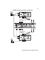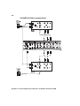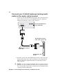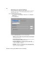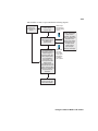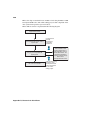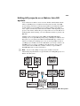
1
Matrox Axio
Installation and User Guide
October 30, 2006
Y10934-201-0250
Trademarks
Matrox Electronic Systems Ltd. ....................................... Matrox®, Axio™, Axio.utils™, DigiSuite™, EZ-MXF™, Flex CPU™,
Flex GPU™, RT.X100™, RT.X2™, X.effects™, X.io™, X.link™,
X.linkHD™, X.linkLE™, X.linkSD™
Adobe Systems Inc.......................................................... Adobe®, After Effects®, Audition®, Encore DVD®, Photoshop®,
Premiere®, Adobe Media Encoder™
Advanced Micro Devices, Inc........................................... AMD Opteron™
Apple Computer, Inc. ....................................................... Apple®, FireWire™
Autodesk, Inc. ................................................................. Autodesk®, 3ds Max®, Combustion®
eyeon Software Inc. ........................................................ Fusion™
Intel Corporation ............................................................. Intel®, Xeon®
International Business Machines Corporation .................. IBM®, VGA®
Microsoft Corporation...................................................... Microsoft®, ActiveMovie®, DirectShow®, DirectX®, Windows®,
Windows Media®, Video for Windows™
NewTek, Inc .................................................................... LightWave 3D®
NVIDIA Corporation.......................................................... NVIDIA®, SLI™
Panasonic (Matsushita Electric Industrial Co.).................. Panasonic®, DVCPRO™, DVCPRO50™, DVCPRO HD™, VariCam®
RealNetworks, Inc. .......................................................... RealNetworks®, RealMedia™
Sony Corporation ............................................................ Sony®, DVCAM™, HDV™, XDCAM™, XDCAM HD™
Victor Company of Japan, Limited (JVC) .......................... JVC™, D-9™, HDV™
ASIO is a trademark and software of Steinberg Media Technologies GmbH.
All other nationally and internationally recognized trademarks and tradenames are hereby acknowledged.
Copyright © 2006 Matrox Electronic Systems Ltd. • All rights reserved.
Disclaimer Matrox Electronic Systems Ltd. reserves the right to make changes in specifications at any time and without notice. The information provided by this document is believed to be accurate and reliable. However, no responsibility is assumed by Matrox Electronic
Systems Ltd. for its use; nor for any infringements of patents or other rights of third parties resulting from its use. No license is granted
under any patents or patent rights of Matrox Electronic Systems Ltd.
Unauthorized recording or use of broadcast television programming, video tape, or other copyrighted material may violate copyright laws.
Matrox Electronic Systems Ltd. assumes no responsibility for the illegal duplication, use, or other acts that infringe on the rights of copyright
owners.
Matrox Electronic Systems Ltd.
1055 St. Regis Blvd., Dorval, Quebec, Canada H9P 2T4
Tel: (514) 685-2630 Fax: (514) 685-2853 World Wide Web: www.matrox.com
i
Matrox Axio License Agreement, Warranty, and Service
A. Matrox software license agreement for single-user products
By installing the software, you, the original purchaser, indicate your acceptance of these terms. If you do not agree
to the terms of this agreement, please return the package unopened.
This Matrox software, any included sample images and other files (the "Software"), is copyrighted by Matrox
Electronic Systems Ltd. All rights are reserved. You are granted a license to use the Software only, subject to the
following restrictions and limitations:
1 The license is to you the original purchaser only, and is not transferable without written permission of Matrox.
2 You may use the Software on a single computer owned or leased by you.
3 You may not use the Software on more than a single machine, even if you own or lease more than one machine,
without the express written consent of Matrox.
4 You may make back-up copies of the Software for your own use only, subject to the use limitations of this
license.
5 You may not engage in, nor permit third parties to engage in, any of the following:
a Providing or disclosing the Software to third parties.
b Providing use of the Software in a computer service business, network, time-sharing, multiple CPU, or multi
user arrangement to users who are not individually licensed by Matrox.
c Making alterations or copies of any kind in the Software (except as specifically permitted above).
d Attempting to disassemble, decompile, or reverse-engineer the Software in any way.
e Granting sublicenses, leases, or other rights in the Software to others.
f Making copies, or verbal or media translations of the user's guide.
g Making telecommunication data transmissions of the Software.
Matrox reserves the right to terminate this license without prejudice to any additional recourses Matrox may have
against you if you violate any of its terms and conditions.
B. Software limited warranty
MATROX WARRANTS TO YOU, THE ORIGINAL PURCHASER, WHO PROVIDES AN ADEQUATE PROOF
OF PURCHASE, THAT THE MEDIA ON WHICH THE SOFTWARE IS RECORDED IS FREE FROM
DEFECTS IN MATERIALS AND WORKMANSHIP UNDER NORMAL USE, AND THAT THE SOFTWARE
WILL PERFORM SUBSTANTIALLY AS DESCRIBED IN THE RELATED DOCUMENTATION PROVIDED
BY MATROX FOR A PERIOD OF NINETY (90) DAYS FROM THE DATE OF PURCHASE.
MATROX PROVIDES YOU THE SOFTWARE AND RELATED DOCUMENTATION ON AN "AS IS" BASIS
WITHOUT ANY WARRANTY OF ANY KIND, EITHER EXPRESSED OR IMPLIED INCLUDING BUT NOT
LIMITED TO ANY IMPLIED WARRANTY OF MERCHANTABILITY, NON-INFRINGEMENT OR FITNESS
FOR A PARTICULAR PURPOSE AS WELL AS THE WARRANTY AGAINST HIDDEN OR LATENT
DEFECTS, ALL OF WHICH. MATROX SPECIFICALLY DISCLAIMS (AND YOU THE ORIGINAL
PURCHASER, BY ACCEPTING THE PRODUCT, SPECIFICALLY ACCEPTS SUCH DISCLAIMER AND
WAIVER) TO THE MAXIMUM EXTENT PERMITTED BY LAW. THE ENTIRE RISK AS TO THE RESULTS
AND PERFORMANCE OF THE SOFTWARE IS ASSUMED BY YOU. SHOULD THE SOFTWARE PROVE
DEFECTIVE YOU (AND NOT MATROX, ITS DISTRIBUTORS OR DEALERS) ASSUME THE ENTIRE
COST OF ALL NECESSARY SERVICING, REPAIR OR CORRECTION.
MATROX DOES NOT WARRANT THAT THE OPERATION OF THE SOFTWARE WILL BE
UNINTERRUPTED OR ERROR-FREE, THAT DEFECTS IN THE SOFTWARE WILL BE CORRECTED, OR
THAT THE SOFTWARE WILL MEET YOUR REQUIREMENTS OR PERFORM WITH ANY HARDWARE OR
SOFTWARE PROVIDED BY THIRD PARTIES.
Matrox Axio License Agreement, Warranty, and Service
ii
C. End-user registration
Before using your Matrox Axio product, please take a moment to register your product in the Matrox Axio Support
section of our web site at www.matrox.com/video/support. The information you provide will assist Matrox to
quickly diagnose and correct any problem that might arise when using the product. Only registered end users are
entitled to customer support.
D. Hardware limited warranty
MATROX WARRANTS TO YOU, THE ORIGINAL PURCHASER, WHO PROVIDES AN ADEQUATE PROOF
OF PURCHASE, THAT THE MATROX AXIO HARDWARE PRODUCTS WILL BE FREE FROM FACTORY
DEFECTS FOR A PERIOD OF ONE (I) YEAR FROM THE DATE OF PURCHASE. MATROX WILL REPAIR
OR REPLACE, AT THE CHOICE OF MATROX, THE MATROX AXIO HARDWARE PRODUCTS WHICH
PROVE TO BE DEFECTIVE DURING THE WARRANTY PERIOD, PROVIDED THAT THEY ARE
RETURNED TO MATROX, SUBJECT TO THE FOLLOWING LIMITATIONS:
Matrox's limited warranty covers only those defects which arise as a result of normal use of the hardware and does
not apply to any:
$
improper or inadequate maintenance;
$
incompatibilities due to the user's hardware or software applications with or in which the Matrox product
interfaces;
$
product of a special or custom-made nature;
$
unauthorized modification or misuse;
$
improper installation, misapplication or negligence;
$
operation outside the product's environmental specifications;
$
improper site preparation or maintenance;
$
software;
$
other causes that do not relate to a product defect;
$
defects or damage suffered as a result of force majeure (including theft);
$
defects or damage suffered as a result of normal wear and tear, and/or
$
stolen goods.
If Matrox receives from you, during the applicable warranty period notice of a defect in a warranted hardware
product and the defective Matrox product in question, Matrox shall at its sole option, either repair or replace the
product, and shall return the repaired product or a replacement product within a reasonable delay. The replacement
product may not be new, provided that it has functionality at least equal to that of the product being replaced. this
warranty is valid in any country where Matrox hardware products are distributed by Matrox or its authorized
dealers.
This limited warranty statement gives you specific legal rights. you may also have other rights which vary from state
to state in the united states, from province to province in Canada, and from country to country elsewhere in the
world.
E. Limitations of warranty
EXCEPT FOR THE SOFTWARE LIMITED WARRANTY AND HARDWARE LIMITED WARRANTY
STATEMENTS, NEITHER MATROX NOR ANY OF ITS THIRD PARTY SUPPLIERS MAKES ANY OTHER
WARRANTY OF ANY KIND, WHETHER EXPRESSED OR IMPLIED, WITH RESPECT TO MATROX
PRODUCTS. MATROX SPECIFICALLY DISCLAIMS (AND YOU, BY ACCEPTING THE MATROX
PRODUCT, SPECIFICALLY ACCEPTS SUCH DISCLAIMER AND WAIVES) ALL OTHER WARRANTIES,
EITHER EXPRESSED OR IMPLIED, INCLUDING BUT NOT LIMITED TO THE IMPLIED WARRANTIES
OF MERCHANTABILITY AND FITNESS FOR A PARTICULAR OR INTENDED PURPOSE OR USE AND
THE WARRANTY AGAINST LATENT DEFECTS, WITH RESPECT TO THE HARDWARE AND/OR
SOFTWARE. MATROX FURTHER DISCLAIMS ANY WARRANTY THAT MATROX PRODUCTS, IN
Matrox Axio License Agreement, Warranty, and Service
iii
WHOLE OR IN PART, WILL BE FREE FROM INFRINGEMENT OF ANY THIRD PARTY INTELLECTUAL
PROPERTY OR PROPRIETARY RIGHTS.
TO THE EXTENT THAT THESE LIMITED WARRANTY STATEMENT ARE INCONSISTENT WITH THE
LAW OF THE LOCALITY WHERE YOU PURCHASED THE MATROX PRODUCT, THESE LIMITED
WARRANTY STATEMENTS SHALL BE DEEMED MODIFIED TO BE CONSISTENT WITH SUCH LOCAL
LAW. UNDER SUCH LOCAL LAW, CERTAIN LIMITATIONS OF THESE LIMITED WARRANTY
STATEMENTS MAY NOT APPLY TO YOU.
TO THE EXTENT ALLOWED BY LOCAL LAW, THE REMEDIES PROVIDED IN THESE LIMITED
WARRANTY STATEMENTS ARE YOUR SOLE AND EXCLUSIVE REMEDIES.
F. Limitations of liability
EXCEPT FOR THE OBLIGATIONS SPECIFICALLY SET FORTH IN THE SOFTWARE LIMITED
WARRANTY AND HARDWARE LIMITED WARRANTY STATEMENTS, IN NO EVENT SHALL MATROX
BE LIABLE FOR ANY DIRECT, INDIRECT, SPECIAL, INCIDENTAL, CONSEQUENTIAL, FORESEEABLE
OR UNFORESEEABLE, OR PUNITIVE DAMAGES, WHETHER BASED ON CONTRACT, TORT, DELICT
OR ANY OTHER LEGAL THEORY AND WHETHER ADVISED OF THE POSSIBILITY OF SUCH
DAMAGES, AND/OR DAMAGES ARISING FROM THE LOSS OF USE, DATA, PRODUCTION REVENUE
AND/OR PROFIT OF IN CONNECTION WITH THE MATROX PRODUCT OR ANY BUSINESS
INTERRUPTION. WITHOUT PREJUDICE TO THE FOREGOING, ANY LIABILITY OF MATROX FOR ANY
BREACH OF WARRANTY SHALL BE LIMITED TO THE AMOUNT PAID BY YOU FOR THE DEFECTIVE
HARDWARE IN QUESTION.
TO THE EXTENT ALLOWED BY LOCAL LAW, MATROX'S ENTIRE LIABILITY AND YOUR EXCLUSIVE
REMEDY SHALL BE THE REPAIR OR REPLACEMENT OF ANY DEFECTIVE PRODUCT DURING THE
WARRANTY PERIOD. MATROX DOES NOT OFFER ANY OTHER WARRANTY WITH RESPECT TO
MATROX HARDWARE OR SOFTWARE OR ANY OTHER HARDWARE OR SOFTWARE.
YOU SHALL BE RESPONSIBLE FOR ALL APPLICABLE TAXES, DUTIES AND CUSTOMS FEES ON ANY
REPLACEMENT UNIT, AS WELL AS ALL TRANSPORT, INSURANCE, STORAGE AND OTHER
CHARGES INCURRED ON ALL RETURNED PRODUCTS.
G. Indemnification disclaimer
Matrox disclaims and shall have no obligation to indemnify or defend you or any third party in respect of any actual
or alleged infringement of any actual or pending patents, copyright or other intellectual property rights. Matrox
shall have no liability arising out of any such actual or alleged intellectual property infringement.
MATROX SPECIFICALLY MAKES NO REPRESENTATION AND DISCLAIMS ALL EXPRESS OR IMPLIED
WARRANTIES OF MERCHANTABILITY, FITNESS FOR A PARTICULAR PURPOSE AND
NONINFRINGEMENT.
Matrox Axio License Agreement, Warranty, and Service
iv
H. Procedure for returning goods
No returned goods, for service or otherwise, will be accepted without prior authorization from Matrox. To obtain
return authorization, contact Matrox Axio Customer Support (see page 294). Once approved, Matrox will contact
you with your Returned Merchandise Authorization (RMA) number. Matrox cannot be responsible for units
returned without an RMA number. Matrox will advise you of the shipping address. The packaging must indicate the
RMA number on the outside. It is strongly recommended that a copy of the original packing slip which states the
serial number of the items you're returning be included with the returned merchandise. This will speed up
processing.
Each individual, returned unit or group of units MUST have an RMA number issued by Matrox. Matrox must
authorize the number of units grouped under one RMA number. Any units received without prior approval by
Matrox will be returned to you freight collect.
You shall be responsible for the cost of consolidated freight (one way only) for warranty units from your location to
the location designated by Matrox. Once repaired, Matrox will incur the cost of consolidated freight for warranty
units to your location.
Matrox Axio License Agreement, Warranty, and Service
Contents
Chapter 1
Introducing Matrox Axio
Welcome to Matrox Axio .................................................................2
Matrox Axio key features.......................................................................2
Features of Matrox Axio HD ..................................................................3
Features of Matrox Axio SD ...................................................................3
Features of Matrox Axio LE ...................................................................3
Hardware supplied for Matrox Axio HD and SD ..............................4
Hardware supplied for Matrox Axio LE ............................................4
Matrox Axio HD and SD system requirements ................................4
Matrox Axio LE system requirements..............................................5
About this manual ............................................................................6
Style conventions...................................................................................6
How video formats are expressed ........................................................6
Last-minute information......................................................................... 7
Chapter 2
Installing Your Matrox Axio HD or SD Hardware
Before you install your Matrox Axio card set................................. 10
Avoid costly damage ........................................................................... 10
Providing adequate ventilation ............................................................. 10
Format your A/V drives using NTFS ..................................................... 12
Use the PCI retainer brackets.............................................................. 13
Removing the PCI retainer bracket ...................................................... 13
Connect the internal power supply cable to your X.io card ................. 14
Set the power selection switch on your X.effects card ........................ 15
Connect the internal power supply cable to your X.effects card ......... 16
Install your Matrox Axio card set ....................................................17
Install your X.io card .............................................................................17
Install your X.effects card .................................................................... 18
Connect the external power supply to your X.effects card ........... 19
Before restarting your computer ................................................... 19
vi
Chapter 3
Connecting External Devices to Matrox Axio HD and SD
X.linkHD and X.linkSD breakout box connections.......................... 22
X.linkHD video connections .................................................................22
X.linkHD audio connections .................................................................22
X.linkSD video connections..................................................................22
X.linkSD audio connections..................................................................22
Prepare for mounting .................................................................... 22
Using the desktop foot ........................................................................23
Attaching the desktop pedestal...........................................................23
Attaching the rackmount brackets ......................................................24
Attach the ferrite beads to the X.link cable ................................... 24
Connect your X.link breakout box to your computer..................... 25
Typical Matrox Axio HD and SD connections ................................ 26
X.linkHD digital video connections .......................................................26
X.linkSD analog component connections............................................. 27
X.linkSD S-Video connections ..............................................................28
X.linkSD digital video connections........................................................29
Chapter 4
Installing Your Matrox Axio LE Hardware
Before you install your Matrox Axio LE card ................................. 32
Avoid costly damage ...........................................................................32
Providing adequate ventilation.............................................................32
Format your A/V drives using NTFS .....................................................34
Use the PCI retainer brackets..............................................................35
Removing the PCI retainer bracket......................................................35
Connect the internal analog audio cable to your Axio LE card ............36
Install your Matrox Axio LE card.................................................... 37
Before restarting your computer................................................... 37
Chapter 5
Connecting External Devices to Matrox Axio LE
X.linkLE breakout box connections ............................................... 40
X.linkLE video connections ..................................................................40
X.linkLE audio connections ..................................................................40
Contents
vii
Attaching the rubber feet to X.linkLE ............................................. 41
Attaching the rackmount brackets to X.linkLE ............................... 41
Connect your X.linkLE audio/video and SDI cables
to the Axio LE card .......................................................................43
Connect your X.linkLE balanced analog audio cable
to the audio cable bracket ...........................................................44
Connect your X.linkLE 1394 cable to your computer .....................45
Using the X.linkLE S-Video adapter cables ....................................45
Typical Matrox Axio LE connections .............................................. 47
X.linkLE analog component connections ............................................. 47
X.linkLE S-Video connections ..............................................................48
X.linkLE digital video connections ........................................................49
Chapter 6
Installing Your Matrox Axio Software
Overview of the software installation ............................................52
Hardware detection .......................................................................52
Installing Adobe Premiere Pro .......................................................52
Installing other third-party programs .............................................53
Installing Matrox Axio.utils .............................................................54
Adding the Matrox WYSIWYG plug-in to NewTek LightWave 3D ..55
Installing additional Matrox effect patterns or
removing unneeded patterns .......................................................55
Installing additional Matrox WYSIWYG plug-ins or
removing unneeded plug-ins........................................................55
Installing the Matrox VFW software codecs on a system
without the Axio hardware ...........................................................56
Removing your Matrox Axio software ...........................................56
Chapter 7
Working with .mxf and .avi files
Working with native .mxf files in Adobe Premiere Pro
and After Effects...........................................................................58
Steps for using .mxf files in your projects ............................................58
Displaying information for clips in Windows Explorer ....................59
Contents
viii
Thumbnail preview ..............................................................................59
Additional file details ............................................................................59
Creating Matrox EZ-MXF files for playback with
VFW applications.......................................................................... 60
Panasonic P2 folder structure ............................................................. 61
Converting a 32-bit .tga sequence to an .avi file with alpha ..........61
Chapter 8
Defining Your Adobe Premiere Pro Settings
A note about running other programs with
Adobe Premiere Pro .................................................................... 66
Loading project presets ................................................................ 66
Setting up your scratch disks ........................................................ 67
Displaying warnings in Adobe Premiere Pro’s Events panel......... 67
Mixing SD and HD clips in a project .............................................. 68
Defining your General settings ...................................................... 69
Selecting options for accelerated Premiere Pro effects....................... 72
Specifying your video output settings (X.linkHD) ................................. 74
Specifying your video output settings (X.linkSD) .................................. 76
Specifying your video output settings (X.linkLE) .................................. 78
Specifying your audio output settings (X.linkHD and X.linkSD) ............. 81
Specifying your audio output settings (X.linkLE) ..................................85
Specifying your genlock settings .........................................................88
Selecting your DV-1394 output settings ...............................................90
Defining your Video Rendering settings ........................................ 90
Defining your Capture settings .......................................................91
Specifying your video capture settings ................................................ 91
Specifying your audio capture settings ................................................95
Specifying your audio monitoring settings (X.linkHD and X.linkSD) ......98
Exporting to a Matrox .avi file........................................................ 99
Exporting to a Matrox .mxf file .....................................................102
Selecting your MPEG-2 I-frame settings ......................................105
Adding a voice-over to your sequence ........................................ 107
Connection and setup ........................................................................107
Recording your voice-over ................................................................ 108
Contents
ix
Exporting using Matrox Media Encoder ....................................... 110
Setting up Matrox DV/HDV device control.....................................111
Exporting your sequence to tape ..................................................111
Preparing your tapes for recording......................................................111
Avoiding missing frames when exporting to DV tape...........................111
Exporting to DV tape using DV-1394 device control ........................... 112
Creating an SD project in 16:9 format........................................... 114
Chapter 9
Setting Up Realtime Effects with Adobe Premiere Pro
Available effects............................................................................ 116
How to apply a Matrox video effect in Adobe Premiere Pro ........ 117
How to apply a Matrox video transition in Adobe Premiere Pro .. 117
Transforming your clip .................................................................. 118
Using the transform controls .............................................................. 118
Transforming a clip in the Program Monitor....................................... 120
Cropping your clip ......................................................................... 121
Using Select Crop .............................................................................. 122
Applying a mask to your effect .................................................... 123
Using Select Mask ............................................................................. 124
Creating a primary color correction............................................. 125
Using Split View ..................................................................................127
Working with Split View in the Program Monitor .................................127
Using the color balance graph ........................................................... 129
Performing an auto balance .............................................................. 132
Matching colors between two clips ................................................... 133
Using the luma mapping graph.......................................................... 135
Creating a secondary color correction........................................ 137
Using the selective key graph............................................................ 142
Creating a color pass effect ...............................................................147
Creating a 3D DVE effect ............................................................. 148
Creating a 4-corner pin effect ..................................................... 150
Creating a blur/soft focus effect .................................................. 152
Overview of the chroma key effects............................................ 153
Contents
x
Creating a chroma key or chroma key shadow effect.................154
Using the chroma key graph to modify key colors and
perform an auto key ..........................................................................157
Creating a cube effect..................................................................160
Creating a crystallize effect..........................................................163
Creating an impressionist effect ..................................................165
Creating a lens flare effect ...........................................................168
Overview of the luma key effect................................................... 170
Creating a luma key effect ............................................................171
Using the luma key graph ...................................................................172
Creating a mask effect ................................................................. 174
Creating a mask blur effect .......................................................... 176
Creating a mask mosaic effect .................................................... 178
Creating a move & scale effect....................................................180
Creating an old movie effect ........................................................182
Creating a page curl effect ..........................................................186
Creating a pan & scan effect .......................................................188
Creating a ripple effect.................................................................190
Creating a shadow effect .............................................................192
Creating a shine effect .................................................................194
Creating a surface finish effect ....................................................198
Creating a track matte effect .......................................................201
Creating a twirl effect .................................................................. 203
Creating a wipe transition ........................................................... 204
Using the Matrox chroma clamper effect ................................... 206
Selecting your speed control method ......................................... 206
About Adobe Premiere Pro’s fixed effects.................................. 206
Matrox Axio realtime guidelines .................................................. 207
Supported graphics formats ..............................................................208
Limitations .........................................................................................208
Contents
xi
Chapter 10
Using Matrox Axio with Video for Windows Programs
Overview ...................................................................................... 210
Using VFW programs without the Axio hardware......................... 211
Before you start rendering ........................................................... 211
Selecting color space conversion options ......................................... 212
Rendering material to a Matrox VFW .avi file .............................. 214
Configuring the Matrox Uncompressed codecs ................................ 215
Configuring the Matrox MPEG-2 I-frame codecs............................... 216
Chapter 11
Using the Matrox WYSIWYG Plug-ins
Overview ......................................................................................220
Configuring the Matrox WYSIWYG Control Panel ........................220
Required steps to use the WYSIWYG plug-ins ............................222
Adobe After Effects ...........................................................................222
Adobe Photoshop..............................................................................222
Autodesk 3ds Max.............................................................................222
Autodesk Combustion .......................................................................222
eyeon Fusion .....................................................................................222
NewTek LightWave 3D ......................................................................223
Chapter 12
Monitoring Your Matrox Axio System
Using X.info to display Axio information .......................................226
Monitoring your Adobe Premiere Pro memory usage........................226
Displaying system information ...........................................................226
Displaying hardware information........................................................228
Monitoring your Axio hardware operating temperatures ...................229
Enabling and disabling the Matrox hardware-accelerated effects
in Adobe Premiere Pro .....................................................................229
Error notification ................................................................................230
Contents
xii
Appendix A
Understanding Standard and Advanced Pulldown
Overview...................................................................................... 232
Standard 2:3 pulldown................................................................. 232
Matrox Axio implementation of standard reverse pulldown...............233
Advanced 2:3:3:2 pulldown ......................................................... 233
Matrox Axio implementation of advanced reverse pulldown .............234
Appendix B
Matrox Axio Workflows
Overview...................................................................................... 236
Working with SD “24P” material .................................................. 236
486p @ 23.98 fps workflow example .................................................238
Working with HD material ............................................................ 239
About the Matrox HD codecs ...................................................... 239
Using the Matrox Offline HD codec ............................................. 240
Creating your offline edit....................................................................240
Creating an offline HD project on a remote editing workstation ........ 241
Recapturing your clips at full HD resolution .......................................242
Offline HD codec workflow examples ................................................244
Using the Matrox MPEG-2 I-frame HD codec ............................. 247
MPEG-2 I-frame HD codec workflow example for offline editing....... 247
MPEG-2 I-frame HD codec workflow example for online editing.......248
Using the Matrox 8-bit and 10-bit Uncompressed HD codecs ... 249
Matrox Uncompressed codec workflow example .............................249
Applying pulldown in HD projects .................................................251
1080p @ 23.98 fps workflow example................................................252
Other Matrox Axio HD workflows ................................................ 253
1080p @ 24 fps workflow example.....................................................253
1080i workflow example ....................................................................254
Mixing 1080p and 1080i @ 25 fps source video ..................................256
720p workflow example..................................................................... 257
Editing HD projects on a Matrox Axio SD system ....................... 259
Supported video compression formats ....................................... 260
Contents
xiii
Matrox Axio HD .................................................................................260
Matrox Axio SD .................................................................................. 261
Matrox Axio LE ..................................................................................262
Supported master output formats on Matrox Axio HD and SD ...263
Supported main and secondary SDI output formats
on Matrox Axio LE ......................................................................264
Appendix C
Matrox Axio Specifications
X.io card .......................................................................................266
General..............................................................................................266
Typical operating voltages and current consumption ........................266
Environmental specifications .............................................................266
X.effects card...............................................................................267
General.............................................................................................. 267
Typical operating voltages and current consumption ........................ 267
Environmental specifications ............................................................. 267
X.linkSD breakout box ..................................................................268
General..............................................................................................268
Typical operating voltages and current consumption ........................268
Video input signals.............................................................................268
Video output signals ..........................................................................269
Audio input/output signals .................................................................269
Audio specifications........................................................................... 270
Environmental specifications ............................................................. 270
X.linkHD breakout box.................................................................. 271
General...............................................................................................271
Typical operating voltages and current consumption .........................271
Video input signals..............................................................................271
Video output signals .......................................................................... 272
Audio input/output signals ................................................................. 272
Audio specifications........................................................................... 273
Environmental specifications ............................................................. 273
Axio LE card .................................................................................274
General.............................................................................................. 274
Typical operating voltages and current consumption ........................ 274
Contents
xiv
Video input signals............................................................................. 275
Video output signals .......................................................................... 276
Audio input/output signals ................................................................. 277
Audio specifications........................................................................... 277
Environmental specifications ............................................................. 277
Appendix D
Matrox Axio Glossary
Glossary of terms ........................................................................ 280
Appendix E
Matrox Axio Customer Support
Getting the most support ............................................................ 294
Registration .......................................................................................294
Keep up to date with our website .....................................................294
Contacting us ....................................................................................294
Index ..................................................................................... 295
Contents
Chapter
1
Introducing Matrox Axio
This chapter outlines some of
the features of Matrox Axio,
lists the contents of your kit,
provides the Axio system
requirements, and describes
the available Matrox Axio
documentation.
2
Welcome to Matrox Axio
The Matrox Axio realtime HD and SD editing platforms let you work at the
highest finishing quality with the most comprehensive realtime feature set and
the most versatile codec technology.
Matrox Axio key features
The following are key features of all Matrox Axio systems:
• Makes Adobe Premiere Pro the foremost HD and SD editor for broadcast
and post production.
• Full-resolution, mixed format, multi-layer realtime editing of HD and SD
video, graphics, and effects.
• Realtime Matrox Flex CPU effects such as color correction, speed changes,
and chroma/luma keying.
• Realtime and accelerated Matrox Flex GPU effects such as 3D DVEs,
blur/glow/soft focus, shine, and much more.
• Native .mxf file support for Panasonic P2, Sony XDCAM, and Sony
XDCAM HD in Adobe Premiere Pro and After Effects.
• Extensive native codec support in HD and SD—uncompressed, MPEG-2
I-frame, DVCPRO HD, MPEG HD, HDV (1080i and 720p), IMX,
DV/DVCAM, DVCPRO, and DVCPRO50.
• Realtime playback of 32-bit compressed and uncompressed .avi files with
alpha.
• 24 fps editing in HD and SD with pulldown, reverse pulldown, and
Panasonic VariCam support.
• Realtime high-quality downconverting from HD to SD.
• Accelerated media encoding, including export to DVD and Adobe Clip
Notes.
• WYSIWYG plug-ins for many popular compositing and animation
programs.
• Matrox EZ-MXF utility for native .mxf file support in Video for Windows
(.avi file) applications.
Chapter 1, Introducing Matrox Axio
3
Features of Matrox Axio HD
• 8-bit or 10-bit uncompressed HD and SD editing.
• Dedicated onboard GPU for support of Matrox Flex GPU effects.
• DV-1394 and SD/HD SDI video input and output.
• RGB and analog component output.
• 2-input/4-output balanced AES/EBU stereo audio pairs, 4-input/4-output
SDI embedded stereo audio pairs.
• 2 balanced analog XLR audio outputs for monitoring purposes.
Features of Matrox Axio SD
• 8-bit or 10-bit uncompressed SD editing and 8-bit uncompressed HD
editing.
• Dedicated onboard GPU for support of Matrox Flex GPU effects.
• DV-1394, composite, S-Video, analog component, and SD-SDI video input
and output.
• 2-input/2-output unbalanced analog RCA audio, 2-input/2-output balanced
analog XLR audio, and 4-input/4-output SDI embedded stereo audio pairs.
• Can be easily upgraded to Matrox Axio HD by simply adding the X.linkHD
breakout box.
Features of Matrox Axio LE
• 8-bit uncompressed HD and SD editing.
• Relies on the power of your system’s GPU to process Matrox Flex GPU
effects.
• DV-1394, composite, S-Video, SD/HD analog component, and SD/HD SDI
video input and output.
• Simultaneous HD and SD output.
• 2-input/6-output balanced analog XLR audio, 1-input/3-output unbalanced
AES/EBU stereo audio pairs, and 1-input/1-output SDI embedded stereo
audio pair.
• 1 unbalanced analog RCA stereo output for monitoring purposes.
Welcome to Matrox Axio
4
Hardware supplied for Matrox Axio HD and SD
• X.io card — input/output card.
• X.effects card — realtime effects co-processor card.
• X.linkHD breakout box for Matrox Axio HD, or X.linkSD breakout box for
Matrox Axio SD.
• X.link cable with attachable ferrite beads.
• 4-to-6 pin IEEE-1394 cable.
• Internal power supply cable for the X.io card.
• Internal power supply cable or 12-volt external power supply for the
X.effects card.
¦ Note The AC outlet cord for your external power supply is not supplied
with Matrox Axio.
Hardware supplied for Matrox Axio LE
• Axio LE card.
• Axio LE internal balanced analog audio cable with attached audio cable
bracket.
• X.linkLE breakout box.
• X.linkLE balanced analog audio cable.
• 6-pin to 6-pin IEEE-1394 cable for connecting X.linkLE to your computer’s
1394 port.
• Two S-Video adapter cables for connecting S-Video devices to X.linkLE.
Matrox Axio HD and SD system requirements
Matrox Axio HD and SD require a computer with the following minimum system
configuration:
• Intel Xeon (dual-CPU) at 3.4 GHz or faster, or AMD Opteron 250
(dual-CPU) or faster.
• An internal power supply of at least 530 watts with one free outlet for the
X.io card, and an additional free outlet if you’ll be providing power to the
X.effects card from your computer’s internal power supply.
• 2 GB or more of physical memory (RAM).
• 2 free PCI-X expansion slots running at 100 MHz.
• Added ventilation (fan) as explained in “Providing adequate ventilation” on
page 10.
• Display card with at least 128 MB of onboard memory.
• DVD-ROM drive for the software installation.
Chapter 1, Introducing Matrox Axio
5
• Microsoft Windows XP with Service Pack 2.
• Adobe Premiere Pro 2.0.
For up-to-date information about Matrox Axio HD and SD system requirements,
contact your Matrox Axio dealer.
¡ Important If you provide power to the X.effects card from your computer’s
internal power supply, upgrading your system with devices that consume a lot of
power can cause your Axio system to become unstable. Devices that consume
considerable power include faster CPUs, advanced display cards (such as cards
that support NVIDIA SLI technology), and additional hard drives. Before
upgrading your system, check with your Matrox Axio dealer. Depending on the
power requirements of your system upgrade, you may need to switch to the
external power supply for the X.effects card.
Matrox Axio LE system requirements
Matrox Axio LE requires a computer with the following minimum system
configuration:
• Intel Xeon (dual-CPU) at 3.4 GHz or faster, or AMD Opteron 250
(dual-CPU) or faster.
• 2 GB or more of physical memory (RAM).
• 1 free PCI-X expansion slot, and a free PCI slot near the Axio LE card to
install the Axio LE balanced analog audio cable bracket.
• Added ventilation (fan) as explained in “Providing adequate ventilation” on
page 32.
• Display card that supports Microsoft DirectX 9 and has at least 256 MB of
onboard memory (512 MB of onboard memory is recommended).
• DVD-ROM drive for the software installation.
• Microsoft Windows XP with Service Pack 2.
• Adobe Premiere Pro 2.0.
For up-to-date information about Matrox Axio LE system requirements, check
the Matrox Video Support site at www.matrox.com/video/support.
Matrox Axio LE system requirements
6
About this manual
This manual provides you with information about installing and using your
Matrox Axio hardware and software, including how to use your Matrox Axio
system with Adobe Premiere Pro.
Style conventions
The following style conventions are used in this manual:
• The names of files, directory paths, and manuals appear in italics. For
example:
$
The data is stored in the sample.wav file.
$
The file is located in your C:\Windows\System directory.
$
Please refer to your Adobe Premiere Pro User Guide.
• Menus and commands that you need to choose are displayed in the form
Menu > Command. For example, File > Save means click File in the
menu bar, then click Save in the menu that appears.
• The names of keys are displayed in small capital bold letters, such as the
CTRL key.
• A plus (+) sign is used to indicate combinations of keys and/or mouse
operations. For example:
$
CTRL+C means to hold down the CTRL key while pressing the C key.
$
SHIFT+click means to hold down the SHIFT key while you click an item
with the mouse.
How video formats are expressed
With the exception of NTSC and PAL, all SD and HD video formats are
expressed in the Matrox Axio documentation and dialog boxes as follows:
VRp or i @ n fps
Where:
• VR is the vertical resolution.
• p or i represents either progressive or interlaced video.
• @ n fps is the frame rate in frames per second.
Here are some examples:
• 486p @ 23.98 fps
per second.
Represents 720×486 progressive video at 23.98 frames
• 720p @ 59.94 fps Represents 1280×720 progressive video at 59.94
frames per second.
Chapter 1, Introducing Matrox Axio
7
• HDV 1080i @ 29.97 fps Represents 1440×1080 interlaced video at 29.97
frames per second. This format is used for HDV material.
• 1080i @ 29.97 fps Represents full-size 1920×1080 interlaced video at
29.97 frames per second.
Last-minute information
Any important information that wasn’t available for inclusion in this manual by
publication time is provided to you in one or both of the following:
• The Axio Readme.htm file on the Matrox Axio installation DVD.
• Matrox Axio Release Notes packaged with this manual.
About this manual
8
Your notes
Chapter 1, Introducing Matrox Axio
2
Installing Your Matrox Axio HD or SD
Hardware
This chapter describes how to
install your Matrox Axio cards
for a Matrox Axio HD or SD
system.
10
Before you install your Matrox Axio card set
Read the following information carefully before attempting to install Matrox
Axio cards in your computer system.
Start with a functioning system
Before attempting any Matrox Axio installation, you should have a computer
system with Windows XP Professional fully installed and functioning smoothly.
This will avoid potential problems later on.
Avoid costly damage
Static electricity from your body can damage your Matrox Axio cards or your
computer. Although you may not notice it, static electricity is generated every
time you move. It’s often too small to cause a spark, but it can still cause damage
to sensitive electronic components or at least reduce their lifespan.
To avoid damage, please observe the following precautions:
• Do not remove your Matrox Axio cards from their antistatic bags until
you’re ready to install them. Before removing the cards, place the packages
within easy reach of the area where you intend to perform the installation.
• You should avoid touching the chips and other components on the circuit
boards. Try to handle the cards by their edges.
• Try to work in an area where the relative humidity is at least 50%.
• Do not wear wool or synthetic clothing. These fabrics tend to generate more
static electricity than cotton, which is best for this kind of work.
• Turn off the power switches on your computer and its connected
components.
Once you’ve opened your computer, drain static electricity from your body by
touching a bare metal surface on your computer chassis before you install or
remove any parts of your system. If you have a grounding wrist strap, use it while
handling and installing any components in your computer.
Providing adequate ventilation
Before using your Matrox Axio-equipped system, you must ensure adequate
ventilation in your computer. Because your Matrox Axio components are
positioned closely together, they produce a significant amount of heat. Forced air
ventilation is therefore extremely important. Inadequate ventilation may result in
erratic operating behavior.
¦ Note Your Matrox Axio system is equipped with numerous temperature
sensors to let you monitor the operating temperature of your various Matrox Axio
hardware components. These temperatures are displayed in the Matrox X.info
program (see “Monitoring Your Matrox Axio System” on page 225 for more
information).
Chapter 2, Installing Your Matrox Axio HD or SD Hardware
11
To provide as much airflow as possible between the cards, you must install a fan
as explained below:
• Position a fan directly facing the end of the Matrox Axio cards with the PCI
retainer brackets. You should make sure the fan directs air between the
various circuit boards. When installed, this fan works in conjunction with
your PC exhaust fan (located at the back of the PC case) to blow warmed air
away from your Axio cards.
Airflow
• Choose a fan that has a minimum rating of 40 CFM (CFM stands for cubic
feet of air displaced per minute and is a measurement standard for fans). An
example of a fan that meets this requirement well is the Sunon model
KD1208PTB1, which is a 12 VDC fan with a rating of 42.5 CFM.
• Make sure to mount the fan as close to the cards as possible. In most
systems, you should be able to place the fan directly behind the card guide
slots.
• Make sure to close your computer’s cover once you’ve finished installing
your hardware. This ensures that the airflow generated by the fan is directed
through the cards and does not escape through the top of your system.
²Caution Fan installation should be done by a qualified technician. Improper
installation procedures can result in damage to your Axio components and/or your
computer system. Matrox Electronic Systems Ltd. is not responsible for any
damage caused by faulty installation.
Before you install your Matrox Axio card set
12
Format your A/V drives using NTFS
Your A/V drives must be formatted using NTFS for use with Matrox Axio
because NTFS overcomes FAT32 file size limitations. When a hard drive is
formatted using FAT32, files saved to this drive cannot exceed 4 gigabytes in
size. This translates to approximately 20 minutes of DV/DVCAM video, which
poses a serious limitation to a nonlinear editing platform like your Matrox Axio
system.
With NTFS, you also have the option of creating a striped volume, which consists
of multiple hard drives formatted as a single partition. This allows you to work
with multiple drives as a single large drive, which offers more disk space and
enhances hard drive performance. NTFS also provides better audio and video
synchronization than FAT32 when you play back your clips.
If you already have Windows installed on your computer, you can check the
format of your drives. In Windows Explorer, right-click the drive letter (such as
D:), then choose Properties. Under General, check the format of your drive
next to File system.
If you need to format a drive using NTFS, right-click My Computer, then
choose Manage. Under Computer Management > Storage, select Disk
Management. In the Disk Management utility, right-click the appropriate
drive and choose Format. In the provided dialog box, specify a volume label for
the partition you are creating. From the File System list, select NTFS. Leave the
Allocation unit size at Default. Do not select the Enable file and folder
compression option. If you are formatting the drive for the first time, do not
select the Perform a quick format option either.
¡ Important
All information on the designated drive will be lost.
For more information on how to format your storage devices using NTFS, see
your Windows documentation.
Disk defragmentation
It’s important to make sure that your storage does not become too fragmented.
Overly fragmented drives will lead to a major reduction in your system’s
performance, which will in turn seriously reduce Matrox Axio’s ability to work
properly.
¡ Important To ensure that your storage is operating at optimal levels,
defragment your hard drives regularly (daily or several times a week).
For information on how to defragment your storage devices, see your Windows
documentation.
Chapter 2, Installing Your Matrox Axio HD or SD Hardware
13
Use the PCI retainer brackets
Many computers contain card guides at the front end of the computer chassis.
These help to stabilize cards. Since PCI-X cards are neither long enough nor
correctly centered to use these guides, the Axio cards are equipped with a PCI
retainer bracket. The following diagram depicts the retainer bracket’s use:
Axio card
PCI retainer
bracket
Card guide
Removing the PCI retainer bracket
With some computer models, you may have to remove the PCI retainer bracket.
In such a case, once you’ve drained static electricity from your body and removed
the Axio cards from their antistatic bags (see “Before you install your Matrox
Axio card set” on page 10), simply remove the screws holding the brackets in
place and then carefully remove the brackets.
Before you install your Matrox Axio card set
14
Connect the internal power supply cable to your
X.io card
Your X.io card requires power from your computer’s internal power supply. An
internal power supply cable is provided with Matrox Axio to connect your X.io
card to your computer’s internal power supply.
Attach the small end of your internal power supply cable to the
8-pin male connector located
near the rear of your X.io card.
Internal
power
supply
cable
LED display
X.io card
X.link breakout box
connector
¦ Note The connector located between the X.link breakout box connector and
the LED display on your X.io card is not used.
When you’ve completed the installation of your Axio card set and turned on your
computer, an LED display on the backplate of your X.io card will light up,
indicating that the internal power supply is properly connected.
Chapter 2, Installing Your Matrox Axio HD or SD Hardware
15
Set the power selection switch on your
X.effects card
Your X.effects card requires additional power, either from your computer’s
internal supply, or from an external power supply. The power selection switch
must be properly set for your card to receive power from your selected power
source. The power selection switch is located at the front of your X.effects card,
near the card bracket.
° To set your X.effects card to receive power from the internal power supply:
Push the power selection switch
towards the back of your X.effects
card as indicated in the following
illustration.
Power selection
switch set for
use with
internal power
supply
X.effects
card
Before you install your Matrox Axio card set
16
° To set your X.effects card to receive power from the external power
supply:
Push the power selection switch towards
the front of your X.effects card as
indicated in the following illustration.
Power selection
switch set for
use with
external power
supply
External power supply
connector
X.effects
card
Connect the internal power supply cable to your
X.effects card
If you set your X.effects card to receive power from your computer’s internal
power supply as explained in the previous section, you must connect the provided
internal power supply cable for X.effects as follows:
Attach the female end of your
internal power supply cable to
the 4-pin male connector located near the middle of your
X.effects card.
Internal power supply
connector
Chapter 2, Installing Your Matrox Axio HD or SD Hardware
Internal
power supply
cable
X.effects card
17
Install your Matrox Axio card set
Your Matrox Axio card set is designed to operate in your computer’s PCI-X slots.
If any of the slots in which you’ll be installing your Axio cards contain other
cards, either move them to unused slots or remove them completely. If you want
to use a 133-MHz slot, then you must configure the slot to run at 100 MHz in the
computer’s BIOS, or using a jumper on the computer’s motherboard. For details
about configuring your computer’s PCI-X slots, see your computer’s
documentation.
To determine the particular slots in which you should install your X.io and
X.effects cards for recommended systems and motherboards, contact your
Matrox Axio dealer.
¡ Important Any components that you have installed in your computer’s PCI-X
slots must operate at 100 MHz or faster. Otherwise, these components might
hinder the performance of your Axio card set.
Install your X.io card
1 Make sure the internal power supply connector is connected to your X.io
card as explained in “Connect the internal power supply cable to your X.io
card” on page 14.
2 Remove the metal plate located at the back of the slot you’ll be using. Save
the screw for the mounting bracket.
3 Position your X.io card over the slot that you’ve chosen and push the card
firmly and evenly until it’s fully seated in the slot.
4 Using the fasten screw, secure your X.io card’s bracket to the computer
frame.
5 Connect the male end of the internal power supply cable to a free power
outlet of your computer’s internal power supply.
¡ Important
Make sure that no other devices are sharing this power outlet.
When you’ve completed the installation of your Axio hardware and turned on
your computer, an LED display on the backplate of your X.io card will light up,
indicating that the internal power supply is properly connected.
Install your Matrox Axio card set
18
Install your X.effects card
1 Make sure the power selection switch of your X.effects card is properly set
as explained in “Set the power selection switch on your X.effects card” on
page 15.
2 If you set your X.effects card to receive power from your computer’s internal
power supply, make sure the internal power supply cable is connected as
explained in “Connect the internal power supply cable to your X.effects
card” on page 16.
3 Remove the metal plate located at the back of the slot you’ll be using. Save
the screw for the mounting bracket.
4 Position your X.effects card over the slot that you’ve chosen and push the
card firmly and evenly until it’s fully seated in the slot.
5 Using the fasten screw you removed in step 3, secure your X.effect card’s
bracket to the computer frame.
6 If you’re using your computer’s internal power supply as an additional power
source for your X.effects card, connect the male end of the internal power
supply cable to a free outlet of your computer’s internal power supply.
¦ Note When you’ve completed the installation of your Axio hardware and
turned on your computer, the LED display on the backplate of your X.effects
card will light up to indicate that the internal power supply is properly
connected.
7 Replace your computer’s cover.
Chapter 2, Installing Your Matrox Axio HD or SD Hardware
19
Connect the external power supply to your
X.effects card
If you’re using the external power supply for your X.effects card, a 12-volt DC
external power supply is included with your Matrox Axio kit.
1 Connect the male connector of your external power supply to the female
power connector of your X.effects card.
X.effects card
External power supply
male connector
2 Attach an AC outlet cord to the external power supply and plug the cord into
an AC outlet (this cord is not supplied with Matrox Axio).
¡ Important You must plug your external power supply cord into an AC
wall outlet. If your computer’s power supply has an external power
connector, you must not use this connector for your X.effect card’s external
power supply.
When you’ve completed the installation of your Axio hardware and turned on
your computer, an LED display on the backplate of your X.effects card will light
up, indicating that the external power supply is properly connected.
Before restarting your computer
You must connect your external devices such as X.link breakout box, VTRs, DV
camcorder, etc., before attempting to restart your computer. For details about
these tasks, see Chapter 3, “Connecting External Devices to Matrox Axio HD
and SD.”
Connect the external power supply to your X.effects card
20
Your notes
Chapter 2, Installing Your Matrox Axio HD or SD Hardware
Chapter
3
Connecting External Devices to Matrox
Axio HD and SD
This chapter shows you how to
connect external devices to
Matrox Axio HD and SD.
22
X.linkHD and X.linkSD breakout box
connections
The X.linkHD and X.linkSD breakout boxes provide you with the maximum
flexibility possible for connecting external video and audio devices to your
Matrox Axio system. The supplied X.link cable is used to connect your X.link
breakout box to your X.io card.
X.linkHD video connections
• One 10-bit 4:2:2 SDI input/output with embedded audio support.
• IEEE-1394 interface.
• Analog black burst reference input.
• Analog component or RGB preview output.
X.linkHD audio connections
• Two balanced AES/EBU stereo inputs.
• Four balanced AES/EBU stereo outputs.
• Two balanced analog XLR outputs for monitoring purposes.
X.linkSD video connections
• One analog component input/output.
• One composite video input/output.
• One S-Video input/output.
• One 10-bit 4:2:2 SDI input/output with embedded audio support.
• IEEE-1394 interface.
• Analog black burst reference input.
X.linkSD audio connections
• Two balanced analog XLR inputs/outputs.
• Two unbalanced analog RCA inputs/outputs.
Prepare for mounting
You have three choices for mounting your X.link breakout box. You can use the
desktop foot or the desktop pedestal to mount your breakout box on your
desktop. You can also use the supplied rackmount brackets to mount your
breakout box to a standard 19” rack.
Chapter 3, Connecting External Devices to Matrox Axio HD and SD
23
Using the desktop foot
Desktop foot
You can use the desktop foot to lay your X.link breakout box flush on your
desktop with its audio/video connections facing up. To use the desktop foot, pull
the foot out from the back of your breakout box and place the breakout box flush
on your desktop.
Attaching the desktop pedestal
Desktop
pedestal
1 Unpack the desktop pedestal.
2 Line up the pedestal guide tabs with the guide slots on the bottom of your
X.link breakout box.
3 Line up the thumb screw on the pedestal with the threaded hole on the X.link
breakout box, and carefully tighten the thumb screw until snug. Do not
overtighten!
¦ Note To remove the desktop pedestal from the breakout box, unscrew the
thumb screw on the pedestal and lift up the breakout box.
Prepare for mounting
24
Attaching the rackmount brackets
Left rackmount bracket
Right rackmount bracket
1 Unpack the two rackmount brackets and their four mounting screws.
²Caution Use only the screws supplied with your Matrox Axio kit to attach
the rackmount brackets to your X.link breakout box. If you use screws that
are larger or longer than the ones supplied, you can damage your equipment.
2 Use the guide tabs on the bracket to help line up each bracket with its
respective screw holes on the back of the breakout box.
¦ Note Be aware that the mounting brackets are different. The left bracket is
wider than the right bracket in order to accommodate the width of the left side
of the breakout box.
3 Using a hand screwdriver only (no power screwdrivers), carefully tighten
each screw until snug. Do not overtighten!
Attach the ferrite beads to the X.link cable
The ferrite beads prevent electromagnetic interference from other electronic
devices.
1 Position an open ferrite bead no more than 1” from one end of the X.link
cable.
2 Snap the ferrite bead shut, enclosing the cable within.
Chapter 3, Connecting External Devices to Matrox Axio HD and SD
25
3 Repeat steps 1 and 2 with the second ferrite bead at the opposite end of the
X.link cable.
Connect your X.link breakout box to your
computer
1 Connect one end of the X.link cable to the X.link connector on the backside
of your X.link breakout box. Tighten the thumb screws until snug to ensure a
stable connection.
X.link cable
X.link cable
connector
2 Attach the opposite end of the X.link cable to the bracket connector on the
backplate of your installed X.io card.
X.link cable
X.io card
²Caution Use extra care when attaching the X.link connectors (bent pins can
cause your Matrox Axio system to not perform properly). Also, do not bend
the attached cable too sharply. Excessive bending or flexing can damage
internal, shielded wires.
Connect your X.link breakout box to your computer
26
Typical Matrox Axio HD and SD connections
Illustrations in the following sections show some typical video connections. In
these illustrations, we’ve connected a Program monitor (NTSC, PAL, or digital)
to view the signal that will be recorded, as well as separate source and record
decks. You may, however, use the same deck as both your source and record
device by making the input and output connections to a single deck.
X.linkHD digital video connections
OUT
IN
ON
AUDIO R
SYNC
AUDIO L
AES/EBU
75 Ω
IN1/2
OUT1/2
SDI
OFF
OUT
VIDEO
DV-1394
Source
(Deck 1)
S-VIDEO
DV-1394 device
HDTV
SDTV
1394
IN
Di gi t al Vi deo Sol ut i ons
REF IN
Y B-Y R-Y
SDI
Y/G
OUT
IN1/2
RGB
B-Y/B
OUT1/2
IN3/4
OUT3/4
OUT1
OUT5/6
AES/EBU
R-Y/R
ANALOG
OUT7/8
OUT2
OUT
GENLOCK
Y/G
SYNC
ON
75 Ω
OFF
AES/EBU
IN1/2
SDI
OUT1/2
OUT
Recorder
(Deck 2)
B-Y/B
IN
SDI
IN
Program
monitor
input
Chapter 3, Connecting External Devices to Matrox Axio HD and SD
R-Y/R
27
X.linkSD analog component connections
Typical Matrox Axio HD and SD connections
28
X.linkSD S-Video connections
Chapter 3, Connecting External Devices to Matrox Axio HD and SD
29
X.linkSD digital video connections
OUT
AUDIO R
IN
AUDIO L
SYNC
ON
75 Ω
OFF
SDI
VIDEO
OUT
DV-1394
S-VIDEO
Source
(Deck 1)
DV-1394 device
IN
1394
Di gi t al Vi deo Sol ut i ons
SDI
Y
B-Y
R-Y
COMPOSITE
S-VIDEO
Ch 1
ANALOG
UNBAL
Ch 2
Ch 1
ANALOG
BAL
Ch 2
REF IN
OUT
GENLOCK
IN
SYNC
ON
75 Ω
OFF
SDI
OUT
Program
monitor
input
SDI
IN
Recorder
(Deck 2)
Typical Matrox Axio HD and SD connections
30
Your notes
Chapter 3, Connecting External Devices to Matrox Axio HD and SD
Chapter
4
Installing Your Matrox Axio LE
Hardware
This chapter describes how to
install your Matrox Axio LE
card.
32
Before you install your Matrox Axio LE card
Read the following information carefully before attempting to install your
Matrox Axio LE card in your computer system.
Start with a functioning system
Before attempting any Matrox Axio LE installation, you should have a computer
system with Windows XP Professional fully installed and functioning smoothly.
This will avoid potential problems later on.
Avoid costly damage
Static electricity from your body can damage your Matrox Axio LE card or your
computer. Although you may not notice it, static electricity is generated every
time you move. It’s often too small to cause a spark, but it can still cause damage
to sensitive electronic components or at least reduce their lifespan.
To avoid damage, please observe the following precautions:
• Do not remove your Matrox Axio LE card from its antistatic bag until you’re
ready to install it. Before removing the card, place the package within easy
reach of the area where you intend to perform the installation.
• You should avoid touching the chips and other components on the circuit
board. Try to handle the card by its edges.
• Try to work in an area where the relative humidity is at least 50%.
• Do not wear wool or synthetic clothing. These fabrics tend to generate more
static electricity than cotton, which is best for this kind of work.
• Turn off the power switches on your computer and its connected
components.
Once you’ve opened your computer, drain static electricity from your body by
touching a bare metal surface on your computer chassis before you install or
remove any parts of your system. If you have a grounding wrist strap, use it while
handling and installing any components in your computer.
Providing adequate ventilation
Before using your Matrox Axio system, you must ensure adequate ventilation in
your computer. Because your Matrox Axio LE card produces a significant
amount of heat, forced air ventilation is extremely important. Inadequate
ventilation may result in erratic operating behavior.
¦ Note Your Matrox Axio system is equipped with numerous temperature
sensors to let you monitor the operating temperature of your various Matrox Axio
hardware components. These temperatures are displayed in the Matrox X.info
program (see “Monitoring Your Matrox Axio System” on page 225 for more
information).
Chapter 4, Installing Your Matrox Axio LE Hardware
33
To provide as much airflow as possible over the card, you must install a fan as
explained below:
• Position a fan directly facing the end of the Matrox Axio LE card with the
PCI retainer bracket. You should make sure the fan directs air over the card.
When installed, this fan works in conjunction with your PC exhaust fan
(located at the back of the PC case) to blow warmed air away from your
Axio LE card.
Airflow
• Choose a fan that has a minimum rating of 40 CFM (CFM stands for cubic
feet of air displaced per minute and is a measurement standard for fans). An
example of a fan that meets this requirement well is the Sunon model
KD1208PTB1, which is a 12 VDC fan with a rating of 42.5 CFM.
• Make sure to mount the fan as close to the card as possible. In most systems,
you should be able to place the fan directly behind the card guide slots.
• Make sure to close your computer’s cover once you’ve finished installing
your hardware. This ensures that the airflow generated by the fan is directed
over the card and does not escape through the top of your system.
²Caution Fan installation should be done by a qualified technician. Improper
installation procedures can result in damage to your Axio LE components and/or
your computer system. Matrox Electronic Systems Ltd. is not responsible for any
damage caused by faulty installation.
Before you install your Matrox Axio LE card
34
Format your A/V drives using NTFS
Your A/V drives must be formatted using NTFS for use with Matrox Axio
because NTFS overcomes FAT32 file size limitations. When a hard drive is
formatted using FAT32, files saved to this drive cannot exceed 4 gigabytes in
size. This translates to approximately 20 minutes of DV/DVCAM video, which
poses a serious limitation to a nonlinear editing platform like your Matrox Axio
system.
With NTFS, you also have the option of creating a striped volume, which consists
of multiple hard drives formatted as a single partition. This allows you to work
with multiple drives as a single large drive, which offers more disk space and
enhances hard drive performance. NTFS also provides better audio and video
synchronization than FAT32 when you play back your clips.
If you already have Windows installed on your computer, you can check the
format of your drives. In Windows Explorer, right-click the drive letter (such as
D:), then choose Properties. Under General, check the format of your drive
next to File system.
If you need to format a drive using NTFS, right-click My Computer, then
choose Manage. Under Computer Management > Storage, select Disk
Management. In the Disk Management utility, right-click the appropriate
drive and choose Format. In the provided dialog box, specify a volume label for
the partition you are creating. From the File System list, select NTFS. Leave the
Allocation unit size at Default. Do not select the Enable file and folder
compression option. If you are formatting the drive for the first time, do not
select the Perform a quick format option either.
¡ Important
All information on the designated drive will be lost.
For more information on how to format your storage devices using NTFS, see
your Windows documentation.
Disk defragmentation
It’s important to make sure that your storage does not become too fragmented.
Overly fragmented drives will lead to a major reduction in your system’s
performance, which will in turn seriously reduce Matrox Axio’s ability to work
properly.
¡ Important To ensure that your storage is operating at optimal levels,
defragment your hard drives regularly (daily or several times a week).
For information on how to defragment your storage devices, see your Windows
documentation.
Chapter 4, Installing Your Matrox Axio LE Hardware
35
Use the PCI retainer brackets
Many computers contain card guides at the front end of the computer chassis.
These help to stabilize cards. Since PCI-X cards are neither long enough nor
correctly centered to use these guides, the Axio LE card is equipped with a PCI
retainer bracket. The following diagram depicts the retainer bracket’s use:
Axio LE card
PCI retainer
bracket
Card guide
Removing the PCI retainer bracket
With some computer models, you may have to remove the PCI retainer bracket.
In such a case, once you’ve drained static electricity from your body and removed
the Axio LE card from its antistatic bag (see “Before you install your Matrox
Axio LE card” on page 32), simply remove the screws holding the brackets in
place and then carefully remove the brackets.
Before you install your Matrox Axio LE card
36
Connect the internal analog audio cable to your
Axio LE card
The Axio LE card includes an internal analog audio cable with an attached audio
cable bracket that allows you to connect the balanced analog audio (XLR) cable
at the back of your X.linkLE breakout box to your Axio LE card.
²Caution The internal audio cable connector and the corresponding connector
on your Axio LE card are designed to fit together such that the tabs on the cable
connector line up with the slots in the card connector. Don’t try to force the audio
cable connector the wrong way. Doing so can cause permanent damage by bending
the pins on the Axio LE card connector.
Connect the internal audio
cable from the audio cable
bracket to the corresponding
connector located near the
middle of your Axio LE card.
Align tabs on audio cable
connector with slots in Axio
LE card connector
Internal audio cable
Audio cable bracket
Axio LE card
Chapter 4, Installing Your Matrox Axio LE Hardware
37
Install your Matrox Axio LE card
Your Matrox Axio LE card is designed to operate in your computer’s PCI-X slot,
and an additional PCI slot near the Axio LE card is required to install the analog
audio cable bracket. If any of the two slots in which you’ll be installing your
Axio LE card and analog audio cable bracket contain other cards, either move
them to unused slots or remove them completely.
To determine the particular slot in which you should install your Axio LE card
for recommended systems and motherboards, see the Matrox Video Support site
at www.matrox.com/video/support.
° To install your Axio LE card
1 Make sure the internal analog audio cable is connected between the Axio LE
card and the audio cable bracket as explained in “Connect the internal analog
audio cable to your Axio LE card” on page 36.
2 Remove the metal plates located at the back of the two slots you’ll be using
for your Axio LE card and the audio cable bracket. Save the screws for the
mounting brackets.
3 Position your Axio LE card and audio cable bracket over the two slots that
you’ve chosen and push them in firmly and evenly until they are fully seated
in the slots.
4 Using the fasten screws you removed in step 2, secure your Axio LE card
and audio cable bracket to the computer frame.
5 Using the four small screws provided with your Axio LE audio cable
bracket, secure the two ends of the audio cable bracket to the computer
frame.
6 Replace your computer’s cover.
Before restarting your computer
You must connect your external devices such as X.linkLE breakout box, VTRs,
DV camcorder, etc., before attempting to restart your computer. For details about
these tasks, see Chapter 5, “Connecting External Devices to Matrox Axio LE.”
Install your Matrox Axio LE card
38
Your notes
Chapter 4, Installing Your Matrox Axio LE Hardware
Chapter
5
Connecting External Devices to Matrox
Axio LE
This chapter shows you how to
connect external devices to
Matrox Axio LE.
40
X.linkLE breakout box connections
The X.linkLE breakout box provides you with the maximum flexibility possible
for connecting external video and audio devices to your Matrox Axio LE system.
Cables are provided for connecting the X.linkLE breakout box to your Axio LE
card and balanced analog audio cable bracket, and a 1394 cable is included with
your Axio LE kit to connect X.linkLE to your computer. S-Video adapter cables
are also provided for connecting S-Video devices.
X.linkLE video connections
• One 4:2:2 SDI input/output with embedded audio support.
• Second 4:2:2 SDI output with embedded audio support (SD-SDI only).
• One analog component input, or one S-Video input, or one composite input.
• One analog component output and one composite output, or one S-Video
output and two composite outputs.
¦ Note Composite output cannot be used when outputting HD analog
component video.
• IEEE-1394 interface.
• Analog black burst reference input.
X.linkLE audio connections
• Two balanced analog XLR inputs.
• Six balanced analog XLR outputs.
• One unbalanced AES/EBU stereo input.
• Three unbalanced AES/EBU stereo outputs.
• One unbalanced analog RCA stereo output for preview.
Chapter 5, Connecting External Devices to Matrox Axio LE
41
Attaching the rubber feet to X.linkLE
You can use the adhesive rubber feet provided with the X.linkLE breakout box if
you’d like to mount the breakout box on your desktop. To do this, peel the rubber
feet from their adhesive backing sheet and attach them to the corresponding
round indentations at the corners on the bottom of the breakout box.
Adhesive rubber foot (x4)
13
dio
g Au
X.linkLE breakout box (partial view)
¦ Note If you later choose to mount your X.linkLE breakout box to a standard
19” rack using the rackmount brackets as explained in the following section, the
breakout box may not fit in the rack unless you remove the adhesive rubber feet.
Attaching the rackmount brackets to X.linkLE
You can use the supplied rackmount brackets to mount your X.linkLE breakout
box to a standard 19” rack.
1 Unpack the two rackmount brackets and their eight mounting screws.
²Caution Use only the screws supplied with your Matrox Axio LE kit to
attach the rackmount brackets to your X.linkLE breakout box. If you use
screws that are larger or longer than the ones supplied, you can damage your
equipment.
2 With the rackmount brackets positioned so that the bracket face is towards
the front of the X.linkLE breakout box, align the screw holes on each
Attaching the rubber feet to X.linkLE
42
rackmount bracket with their respective screw holes on either end of the
X.linkLE breakout box.
X.linkLE breakout box (partial view)
ANAL
OG
CVBS
IN
IN 1
IN 2
OUT 1
Rackmount
bracket
Pb/Y IN
Pr/C IN
ANAL
OG
VIDEO
OUT 2
IN
SDI
Y/CVB
S OUT
Pb/Y OU
T Pr/C
OUT
CVBS
OUT
OUT 1
REF IN
OUT 2
1394
75 OH
M
Rackmount bracket
3 Using a hand screwdriver only (no power screwdrivers), carefully tighten
each screw until snug. Do not overtighten!
Chapter 5, Connecting External Devices to Matrox Axio LE
43
Connect your X.linkLE audio/video and SDI
cables to the Axio LE card
1 Connect the X.linkLE audio/video cable from the back of the X.linkLE
breakout box to the X.linkLE audio/video cable connector (labeled B) on
your installed Axio LE card. Tighten the thumb screws until snug to ensure a
stable connection.
Back of X.linkLE breakout box (partial view)
Axio LE audio/video
cable connector (B)
X.linkLE audio/video cable
B
SDI OUT A
OUT A
SDI OUT B
OUT B
Axio LE
SDI
connectors
SDI IN
IN
X.linkLE SDI cable
Axio LE card bracket
2 Connect the X.linkLE SDI cable from the back of the X.linkLE breakout box
to the respective SDI connectors (labeled OUT A, OUT B, and IN) on your
installed Axio LE card.
²Caution Use extra care when attaching the cables to their respective
connectors (bent pins can cause your Matrox Axio LE system to not perform
properly). Also, do not bend the attached cables too sharply. Excessive
bending or flexing can damage internal, shielded wires.
Connect your X.linkLE audio/video and SDI cables to the Axio LE card
44
Connect your X.linkLE balanced analog audio
cable to the audio cable bracket
1 Connect one end of the X.linkLE balanced analog audio cable to the Analog
Audio connector at the back of your X.linkLE breakout box. Tighten the
thumb screws until snug to ensure a stable connection.
Analog Audio
Back of X.linkLE breakout
box (partial view)
Axio LE balanced analog
audio cable connector (A)
X.linkLE balanced analog
audio cable
A
Axio LE audio cable
bracket
2 Attach the opposite end of the X.linkLE balanced analog audio cable to the
balanced analog audio cable connector (labeled A) on your installed Axio
LE audio cable bracket. Tighten the thumb screws until snug to ensure a
stable connection.
²Caution Use extra care when attaching the cable to its respective connector
(bent pins can cause your Matrox Axio LE system to not perform properly).
Also, do not bend the attached cable too sharply. Excessive bending or flexing
can damage internal, shielded wires.
Chapter 5, Connecting External Devices to Matrox Axio LE
45
Connect your X.linkLE 1394 cable to your
computer
1 Connect one end of the X.linkLE 1394 cable to the 1394 connector at the
back of your X.linkLE breakout box.
Back of X.linkLE
breakout box
(partial view)
Analog Audio
1394
1394 cable connector
bracket on your computer
1394
X.linkLE 1394 cable
2 Attach the opposite end of the X.linkLE 1394 cable to the 1394 connector on
your computer.
Using the X.linkLE S-Video adapter cables
To support S-Video (Y/C) connections to your X.linkLE breakout box, your Axio
LE kit includes two S-Video adapter cables (one for S-Video input and one for SVideo output).
¦ Note When you connect an S-Video device to the X.linkLE breakout box,
you won’t be able to connect an analog component device at the same time.
1 For S-Video input, connect the S-Video adapter cable labeled Y to the Pb/Y
IN connector, and connect the S-Video adapter cable labeled C to the Pr/C
IN connector, at the front of the X.linkLE breakout box.
2 Connect the other end of the cable to the S-Video OUT connector on your
source device.
Connect your X.linkLE 1394 cable to your computer
46
To S-Video OUT connector
on source device
X.linkLE S-Video adapter cable
C
Y
X.linkLE breakout
box (partial view)
Y/CVBS IN
IN 1/2
Pb/Y IN
Pr/C IN
IN
DIGITAL AUDIO
AES/EBU
ANALOG
VIDEO
OUT 1/2 OUT 3/4 OUT 5/6
Y/CVBS OUT Pb/Y OUT Pr/C OUT CVBS OUT
SDI
REF IN
OUT 1
OUT 2
1394
75 OHM
3 For S-Video output, connect the S-Video adapter cable labeled Y to the Pb/Y
OUT connector, and connect the S-Video adapter cable labeled C to the Pr/C
OUT connector, at the front of the X.linkLE breakout box.
4 Connect the other end of the cable to the S-Video IN connector on your
record device.
Y/CVBS IN
IN 1/2
Pb/Y IN
Pr/C IN
IN
ANALOG
VIDEO
DIGITAL AUDIO
AES/EBU
SDI
REF IN
OUT 1/2 OUT 3/4 OUT 5/6
Y/CVBS OUT Pb/Y OUT Pr/C OUT CVBS OUT
OUT 1
OUT 2
1394
75 OHM
X.linkLE breakout
box (partial view)
Y
C
X.linkLE S-Video adapter cable
To S-Video IN connector
on record device
Chapter 5, Connecting External Devices to Matrox Axio LE
47
Typical Matrox Axio LE connections
Illustrations in the following sections show some typical video connections. In
these illustrations, we’ve connected a Program monitor (NTSC, PAL, or digital)
to view the signal that will be recorded, as well as separate source and record
decks. You may, however, use the same deck as both your source and record
device by making the input and output connections to a single deck.
X.linkLE analog component connections
Source
(Deck 1)
External
sync
source
COMPONENT
VIDEO
AUDIO
IN
IN
SYNC
OUT
ON
Y
B-Y
75 Ω
R-Y
SYNC
OFF
OUT
OUT
ANALOG AUDIO
IN 1/2
AUDIO
PREVIEW
Y/CVBS IN
Pb/Y IN
Pr/C IN
IN
DIGITAL AUDIO
AES/EBU
ANALOG
VIDEO
OUT 1/2 OUT 3/4 OUT 5/6
Y/CVBS OUT Pb/Y OUT Pr/C OUT CVBS OUT
SDI
REF IN
IN 1
IN 2
OUT 1
OUT 2
OUT 3
OUT 4
Recorder
(Deck 2)
OUT 5
OUT 6
AUDIO
IN
OUT
OUT 2
1394
75 OHM
COMPONENT
VIDEO
IN
Y
Program
monitor
input
OUT 1
B-Y
R-Y
ON
75 Ω SYNC
OFF
OUT
VIDEO
IN
Typical Matrox Axio LE connections
48
X.linkLE S-Video connections
The X.linkLE breakout box does not have standard S-Video connectors, however
you can still connect S-Video devices to your X.linkLE breakout box by using the
two supplied X.linkLE S-Video adapter cables (see “Using the X.linkLE S-Video
adapter cables” on page 45 for more information).
Source
(Deck 1)
AUDIO
S-VIDEO
IN
IN
External
sync
source
ON
75 Ω
SYNC
OUT
SYNC
OFF
OUT
OUT
X.linkLE S-Video adapter
cable
C
Y
ANALOG AUDIO
IN 1/2
AUDIO
PREVIEW
Y/CVBS IN
Pb/Y IN
Pr/C IN
IN
DIGITAL AUDIO
AES/EBU
ANALOG
VIDEO
OUT 1/2 OUT 3/4 OUT 5/6
Y/CVBS OUT Pb/Y OUT Pr/C OUT CVBS OUT
SDI
REF IN
IN 1
IN 2
OUT 1
OUT 2
OUT 3
OUT 4
OUT 5
OUT 6
OUT 1
OUT 2
1394
75 OHM
Y
C
Recorder
(Deck 2)
AUDIO
S-VIDEO
IN
IN
ON
75 Ω
SYNC
OFF
OUT
OUT
Program
monitor
input
VIDEO
IN
Chapter 5, Connecting External Devices to Matrox Axio LE
49
X.linkLE digital video connections
External
sync
source
SYNC
OUT
OUT
IN
ON
AES/EBU
75 Ω
SYNC
IN1/2
AUDIO R
SDI
OUT1/2
OFF
AUDIO L
OUT
VIDEO
Source
(Deck 1)
DV-1394
S-VIDEO
DV-1394 device
ANALOG AUDIO
Y/CVBS IN
IN 1/2
AUDIO
PREVIEW
Pb/Y IN
Pr/C IN
IN
DIGITAL AUDIO
AES/EBU
ANALOG
VIDEO
OUT 1/2 OUT 3/4 OUT 5/6
Y/CVBS OUT Pb/Y OUT Pr/C OUT CVBS OUT
SDI
REF IN
IN 1
IN 2
OUT 2
OUT 1
OUT 3
OUT 4
OUT 5
OUT 6
Recorder
(Deck 2)
OUT 2
1394
75 OHM
Program
monitor input
Y/G
B-Y/B
R-Y/R
Y/G
B-Y/B
R-Y/R
IN
ON
SYNC
OUT 1
75 Ω
OFF
AES/EBU
IN1/2
OUT1/2
SDI
OUT
SDI
IN
SDI
IN
Program
monitor input
Typical Matrox Axio LE connections
50
Your notes
Chapter 5, Connecting External Devices to Matrox Axio LE
Chapter
6
Installing Your Matrox Axio Software
This chapter explains how to
install the software required to
use your Matrox Axio system.
52
Overview of the software installation
Once you’ve installed your Matrox Axio hardware and properly connected your
devices, you can proceed with the software installation. This includes installing
Adobe Premiere Pro and Matrox Axio.utils. Matrox Axio.utils installs the drivers
for your Matrox Axio hardware and the Matrox Axio realtime plug-in for Adobe
Premiere Pro.
Hardware detection
Turn on your computer. Once Windows restarts, the “Found New Hardware
Wizard” detects your Matrox Axio hardware. Because the Matrox Axio.utils
Setup program will automatically detect your devices and install the appropriate
drivers, simply press ESC or click Cancel to close the “Found New Hardware
Wizard.”
¡ Important The “Found New Hardware Wizard” will appear for each of your
Axio hardware components. Make sure that you close the “Found New Hardware
Wizard” each time it appears. To ensure a smooth Matrox Axio software
installation, it is essential that you do not let the “Found New Hardware Wizard”
try to install any drivers.
The “Found New Hardware Wizard” will only appear the first time you start your
computer after installing your Axio hardware.
Installing Adobe Premiere Pro
You must install Adobe Premiere Pro before installing Matrox Axio.utils.
¡ Important You must install Adobe Premiere Pro and Matrox Axio.utils on an
NTSF-formatted drive (usually your system drive).
° To install Adobe Premiere Pro:
1 Close all Windows programs.
2 Insert the Adobe Premiere Pro installation DVD in your DVD-ROM drive.
3 From the displayed menu, choose to install Adobe Premiere Pro. When the
setup program starts, follow the onscreen instructions.
¦ Note When you install Matrox Axio.utils, Matrox plug-in files will be added to
your Adobe Premiere Pro’s Plug-ins folder on your hard drive. Therefore, if you
later re-install Adobe Premiere Pro to a different directory, you’ll need to
un-install and re-install Matrox Axio.utils.
Chapter 6, Installing Your Matrox Axio Software
53
Installing other third-party programs
There are a number of programs for which you can choose to install a Matrox
WYSIWYG (What You See Is What You Get) plug-in that lets you see your work
directly on your video monitor. For example, the Matrox WYSIWYG plug-in for
Adobe After Effects lets you display the contents of your composition on your
video monitor to see the exact color temperature, safe-title area, and any
interlaced artifacts as you work. The following programs are supported:
• Adobe After Effects (version 5.0 or later).
• Adobe Photoshop (version 7.0 or later).
• Autodesk 3ds Max (version 7.0 or later).
• Autodesk Combustion (version 4 or later).
• eyeon Fusion (version 4 or later).
• NewTek LightWave 3D (version 7.5 or later).
If you have any of these programs, you should install them now so that you’ll be
able to install the Matrox WYSIWYG plug-in for them when you install Matrox
Axio.utils. You can, however, install the Matrox WYSIWYG plug-in for a
program at any time after installing Axio.utils as explained in the section
“Installing additional Matrox WYSIWYG plug-ins or removing unneeded
plug-ins” on page 55.
¦ Note When you install the Matrox WYSIWYG plug-in for a program, Matrox
plug-in files will be added to a folder for that program on your hard drive.
Therefore, if you later re-install the program to a different folder, you’ll need to
also re-install the Matrox WYSIWYG plug-in.
Installing other third-party programs
54
Installing Matrox Axio.utils
1 Insert your Matrox Axio installation DVD in your DVD-ROM drive.
Windows automatically starts the Matrox Axio menu.
2 From the Matrox Axio menu, choose Install Matrox Axio.utils.
3 If any of your Matrox Axio hardware needs a firmware update, the updater
will be launched automatically at this point. Once completed, the Axio.utils
install will continue.
4 Follow the onscreen instructions to install Matrox Axio.utils on your
computer. You’ll be prompted to install the Matrox effect patterns (GFX
files) for selected video formats. For example, you can choose to install the
SD NTSC and HD 1080 patterns only. You’ll also be prompted to install the
Matrox WYSIWYG plug-ins for any supported programs that are currently
installed on your system.
¦ Note Some versions of LightWave 3D may not be automatically detected
by the Setup program. If this happens, click Browse to select the folder where
you installed LightWave 3D.
5 If required, the Setup program will restart your computer when you click
OK.
¦ Note The first time you install Matrox Axio.utils on an Axio LE system, the
Matrox GPU Performance Analyzer will automatically be run to optimize your
Chapter 6, Installing Your Matrox Axio Software
55
GPU for use with Axio LE. You can run this program manually if requested by
Matrox Customer Support by choosing Start > All Programs > Matrox
Axio.utils > Matrox GPU Performance Analyzer.
Adding the Matrox WYSIWYG plug-in to
NewTek LightWave 3D
When you install the Matrox WYSIWYG plug-in for NewTek LightWave 3D, the
plug-in is copied to your hard drive. You must then add the plug-in to NewTek
LightWave 3D as follows:
1 Start NewTek LightWave 3D.
2 Choose Layout > Plug-ins > Add Plug-ins.
3 Open the Input-Output folder or the folder where you chose to install the
Matrox WYSIWYG plug-in, and double-click the mvelwpreview.p file.
4 Click the OK button in the Add Plug-ins dialog box.
Installing additional Matrox effect patterns or
removing unneeded patterns
When you install Matrox Axio.utils, you are asked to select the video formats for
which you want to install the Matrox effect patterns (GFX files). If after you’ve
installed Matrox Axio.utils you find that you need to install patterns for
additional video formats or remove patterns for formats that you no longer use,
you can run the Matrox Effect Patterns Setup program by choosing Install
Matrox effect patterns from the Matrox Axio menu. You’ll be prompted to
select the video formats for which you want to install the Matrox effect patterns,
and clear the selections for currently installed patterns that you want to be
removed.
Installing additional Matrox WYSIWYG plug-ins
or removing unneeded plug-ins
When you install Matrox Axio.utils, you are prompted to install the Matrox
WYSIWYG plug-ins for any supported programs that are currently installed on
your system. If after you’ve installed Matrox Axio.utils you want to install
additional Matrox WYSIWYG plug-ins, or re-install or remove a currently
installed plug-in, you can run the Matrox WYSIWYG Plug-ins Setup program by
choosing Install Matrox WYSIWYG Plug-ins from the Matrox Axio menu.
You’ll be prompted to specify which plug-ins you want to install, re-install, or
remove. For more information about the programs supported and required
settings, see “Using the Matrox WYSIWYG Plug-ins” on page 219.
Adding the Matrox WYSIWYG plug-in to NewTek LightWave 3D
56
¦ Note To install the Matrox WYSIWYG plug-in for a program, you must first
install that program.
Installing the Matrox VFW software codecs on
a system without the Axio hardware
The Matrox VFW software codecs let you render (compile) and play back
Axio- compatible .avi files in your Video for Windows programs without having
the Matrox Axio hardware installed in your computer.
Remarks
• If you have the Matrox Axio hardware, you do not need to install the VFW
software codecs because Matrox Axio.utils installs all the required Matrox
codecs on your system.
• If you have a previous version of the Matrox VFW software codecs that was
provided with another Matrox product (such as Matrox DigiSuite or Matrox
RT.X100), you must remove those codecs from your computer using Add or
Remove Programs in Windows Control Panel before installing the VFW
software codecs provided with Matrox Axio.
° To install the Matrox VFW software codecs:
1 From the Matrox Axio menu, choose Install Matrox VFW software
codecs.
2 Follow the onscreen instructions. An information box indicates when the
installation is complete.
Removing your Matrox Axio software
You can remove the various Matrox Axio software components as follows:
• To remove Matrox Axio.utils from your computer, choose Start > All
Programs > Matrox Axio.utils > Uninstall Matrox Axio.utils. You can
also choose Uninstall Matrox Axio.utils from the Matrox Axio menu.
• To remove only the Matrox effect patterns from your computer, choose
Start > All Programs > Matrox Axio.utils > Uninstall Matrox Effect
Patterns. You should not remove only the Matrox effect patterns unless
you’ll be re-installing Matrox Axio.utils.
• To remove only the Matrox WYSIWYG plug-ins from your computer,
choose Start > All Programs > Matrox Axio.utils > Uninstall Matrox
WYSIWYG Plug-ins.
• To remove the Matrox VFW software codecs from a computer without the
Matrox Axio hardware, use Add or Remove Programs in Windows
Control Panel.
Chapter 6, Installing Your Matrox Axio Software
Chapter
7
Working with .mxf and .avi files
This chapter shows you how to
work with .mxf and .avi files on
Matrox Axio.
58
Working with native .mxf files in Adobe
Premiere Pro and After Effects
Matrox Axio supports the MXF file format, which allows you to use .mxf files
that are created with the Panasonic P2, Sony XDCAM, or Sony XDCAM HD
camera directly in Adobe Premiere Pro and After Effects without having to
convert the files to the traditional AVI file format.
¡ Important For Panasonic P2 cameras, if you are shooting material at 1080p or
486p @ 23.98 fps for use with Matrox Axio, you must set the camera to
Advanced mode (1080/24pA or 486/24pA).
Steps for using .mxf files in your projects
1 Connect your Panasonic P2 or Sony XDCAM/XDCAM HD device to your
Matrox Axio computer as per your device’s instructions.
¦ Note For Panasonic P2 devices, if you have a PCMCIA card reader in your
computer, you can use it to connect to Matrox Axio, however the device must
show up in Microsoft Windows as a drive.
2 For a Panasonic P2 device, you can either edit directly from the P2 device or
from the computer’s hard drive. If you choose to edit your .mxf clips from the
computer, copy the Panasonic P2 folder structure to your computer’s hard
drive. For information regarding the Panasonic P2 folder structure, see
“Panasonic P2 folder structure” on page 61.
For a Sony XDCAM or XDCAM HD device, you cannot edit directly from
the device. Therefore, you must copy the files to your computer’s hard drive
using a browser such as Windows Explorer.
3 Prepare the native .mxf files for editing in Adobe Premiere Pro by importing
them into the Project panel like any other file. To help you select your shots
you can enable thumbnail view, and add details for your .mxf files in
Windows Explorer, or Premiere Pro’s Import or Get Properties dialog box.
For more information on displaying .mxf file information, see “Displaying
information for clips in Windows Explorer” on page 59.
4 Edit your project with the native .mxf files from the Project panel, applying
effects, and mixing the .mxf files with other .avi files as you see fit.
5 Add Adobe After Effects compositing with a simple copy and paste or
import the .mxf files into After Effects and edit them as you see fit.
6 Export your project to a wide variety of formats, including a P2- or
XDCAM-compatible .mxf file as explained in “Exporting to a Matrox .mxf
file” on page 102.
Chapter 7, Working with .mxf and .avi files
59
Displaying information for clips in Windows
Explorer
Matrox Axio extends the functionality of Windows Explorer by allowing you to
easily view and manage your .mxf and .avi files by providing thumbnail previews
and additional file details.
¦ Note You can view thumbnails and additional details for .mxf and .avi files in
any application where you can choose the thumbnails or details view, such as
Adobe Premiere Pro’s Import dialog box. For file details, after you add or
remove details in a specific folder, you must apply the change to all folders by
choosing View > Folder Options > View > Apply to All Folders.
Thumbnail preview
Matrox Axio allows you to view thumbnails of .mxf and .avi files in Windows
Explorer. In a folder containing .mxf or .avi files, simply enable the thumbnails
view (choose View > Thumbnails) and the first frame of each clip will be
displayed as a thumbnail. Without Matrox Axio, only the default Windows icon
would appear.
Additional file details
Matrox Axio lets you add additional details for .mxf and .avi files in Windows
Explorer.
° To add clip details in Windows Explorer:
1 Start Windows Explorer, and ensure that the details view is selected for the
appropriate folder by choosing View > Details.
2 Choose View > Choose Details.
Displaying information for clips in Windows Explorer
60
3 In the Choose Details dialog box, select the check boxes corresponding to
the desired “Matrox” or “Matrox P2” details. Detail names followed by
“Matrox P2” are specific to Panasonic P2 files (for example, User Clip
Name, Shooter, Shooting Location, and Scene No.).
4 Click OK.
Creating Matrox EZ-MXF files for playback with
VFW applications
Many animation, compositing, and motion graphics applications used by video
editors read Video for Windows (VFW) .avi files, but these applications are not
designed to read .mxf files. The Matrox EZ-MXF utility creates a very small
reference .avi file, along with the associated mono .wav files, from an .mxf file
without modifying the contents of your original .mxf file or its metadata. Your
VFW application plays the created .avi and .wav files, which reference the
original .mxf file.
¦ Note Windows Media Player does not support .mxf files. You can therefore use
the Matrox EZ-MXF utility to create reference .avi and .wav files for your .mxf
files that you want to play back using Windows Media Player.
You can configure Matrox EZ-MXF to create only video files, only audio files, or
both types of files. By default, Matrox EZ-MXF is set to create both video and
audio files.
° To create Matrox EZ-MXF files:
1 In Windows Explorer, right-click the desired .mxf file (or selected files), and
choose Matrox EZ-MXF AVI > Configure.
2 In the Configure Matrox EZ-MXF AVI dialog box, specify the type of files
you want to create (video and/or audio), and then click OK.
¦ Note The file type settings will remain in effect until you change them.
3 Right-click the desired .mxf file (or selected files), and choose Matrox
EZ-MXF AVI > Create. The reference .avi and .wav files for Sony
XDCAM/XDCAM HD are created in the same folder as your source .mxf
Chapter 7, Working with .mxf and .avi files
61
files. Panasonic P2 files are created as per the folder structure for Panasonic
P2 as explained in the next section.
¡ Important Once the Matrox EZ-MXF files are created, do not change the
location or name of the referenced .mxf files or your VFW program won’t be
able to locate your .mxf material. If this occurs, Matrox Axio will display an
appropriate error message.
Panasonic P2 folder structure
Panasonic P2 files are organized in a specific folder structure as follows:
When you select an .mxf file in the VIDEO folder, Matrox EZ-MXF looks for any
associated audio .mxf files in the AUDIO folder, and creates the reference .avi and
associated .wav files in the VIDEO folder. For example, if you select the file
00001A.mxf from the VIDEO folder, the reference .avi file (00001A.avi) and all
associated audio files, such as 00001A00.Mono.wav and 00001A01.Mono.wav,
will be created in the VIDEO folder. For more information on the P2 naming
convention and folder structure, see your Panasonic P2 documentation.
¦ Note If you select an audio .mxf file from the AUDIO folder, only the mono
.wav file will be created, and it will be in the AUDIO folder.
Converting a 32-bit .tga sequence to an .avi file
with alpha
Matrox Axio allows you to create a single .avi file with alpha from a 32-bit .tga
sequence. The created .avi file will contain the alpha-key information, which
means that when you place the file on the timeline in Adobe Premiere Pro, the
clip will be automatically keyed. Having only one file simplifies management
and makes it easier to include the composition in your final edit.
¦ Note You can convert 32-bit uncompressed or RLE-compressed .tga files to an
.avi file with alpha.
When selecting only one .tga file, the program automatically detects other files
with the same base name in the same folder (for example, demo001.tga,
demo002.tga, etc.), and uses these files to create the .avi file. When multiple .tga
Converting a 32-bit .tga sequence to an .avi file with alpha
62
files are selected, only the selected files will be taken to build the .avi file. The
.avi file will be created with the following naming convention:
Base Name_Compressor_Output Format.avi.
For example, if the base name for your converted .tga sequence is demo, the
compressor is Matrox MPEG-2 I-frame+ Alpha, and the output format is
720p@25 fps, the created .avi file will be named
[email protected].
You’re able to create HD and SD .avi files with alpha in Matrox uncompressed or
MPEG-2 I-frame format.
° To create an .avi file with alpha from a .tga sequence:
1 In Windows Explorer, right-click the selected .tga file(s), choose Matrox
AVI + Alpha > Select Format, and then click the desired .avi output video
format, such as 1080p @ 23.98 fps.
¦ Note Formats that are not supported by your Matrox Axio hardware are
identified with an asterisk (*) in the list. If you create an .avi file using an
unsupported format, it will not play back in real time on your Axio system.
2 Right-click the selected .tga file(s), and choose Matrox AVI + Alpha >
Configure.
¦ Note Once set, the output format and configuration settings apply to all
subsequent .tga sequences that you convert to .avi files. If however, you select
an HDV 1080i output format, the compressor for the .tga to .avi conversion
will automatically be set to Matrox MPEG-2 I-frame HD + Alpha.
Chapter 7, Working with .mxf and .avi files
63
3 From the Compressor list, select the compression format you want for your
.avi file.
¦ Note The compression formats that are available in the Compressor list
depend on your selected output video format and Matrox Axio hardware. For
example, if you select an SD format, only SD compression formats will be
available.
Renders video to 8-bit
$
Matrox 8-bit Uncompressed + Alpha
uncompressed format with alpha.
$
Matrox 10-bit Uncompressed + Alpha Renders video to 10-bit
uncompressed format with alpha. (Not supported on Matrox Axio LE.)
$
Matrox MPEG-2 I-frame + Alpha
$
Matrox MPEG-2 I-frame HD + Alpha Renders video to MPEG-2
intra-frame format with alpha using the 4:2:2 Profile @ High Level at a
selected data rate (HD resolution only).
Renders video to MPEG-2
intra-frame format with alpha using the 4:2:2 Profile @ Main Level at a
selected data rate (SD resolution only).
4 If you selected the Matrox MPEG-2 I-frame + Alpha or Matrox MPEG-2
I-frame HD + Alpha format, click the Configure button to specify various
options for the MPEG-2 I-frame compression. The configuration options are
the same as when you capture or export video using Adobe Premiere Pro
(see “Selecting your MPEG-2 I-frame settings” on page 105).
5 Under Destination Folder, either select Same folder as TGA, or click
Browse to specify where the .avi file will be created. Select Overwrite
existing file if you want to overwrite any .avi file with the same name in the
specified folder.
6 Right-click the selected .tga file(s), and choose Matrox AVI + Alpha >
Convert to AVI.
Converting a 32-bit .tga sequence to an .avi file with alpha
64
Your notes
Chapter 7, Working with .mxf and .avi files
Chapter
8
Defining Your Adobe Premiere Pro
Settings
This chapter explains how to
define various settings for
using Matrox Axio with Adobe
Premiere Pro. This includes
specifying your project and
export settings.
66
A note about running other programs with
Adobe Premiere Pro
For the best performance, you shouldn’t run any other programs at the same time
as Adobe Premiere Pro. If you choose to do so, however, make sure that you start
Adobe Premiere Pro and open your Matrox Axio project before starting the other
programs. Otherwise, Adobe Premiere Pro may fail to start. If this happens, quit
all programs and then restart Adobe Premiere Pro.
¥ Tip When Adobe Premiere Pro is running, you can monitor your Adobe
Premiere Pro memory usage. To do this, hold your mouse pointer over the
Matrox X.info ( ) icon. For details on using Matrox X.info, see Chapter 12,
“Monitoring Your Matrox Axio System.”
Loading project presets
The Matrox realtime plug-in for Adobe Premiere Pro includes project presets that
you can load to immediately apply appropriate Matrox Axio settings. For more
information about using the Matrox project presets for working with different
types of projects, see Appendix B, “Matrox Axio Workflows.”
° To load a Matrox project preset:
1 Start Adobe Premiere Pro. The New Project dialog box appears.
2 From the appropriate Matrox folder (Matrox - SD to create an SD project,
or Matrox - HD to create an HD project), select the preset that matches the
type of project you want to create. For example, if you want to create an
NTSC project in which you’ll capture clips to DV/DVCAM format and work
in a standard 4:3 editing environment, expand the NTSC and Standard
folders under Matrox - SD, then select the DV preset.
¦ Note If you’ll be capturing HDV material, select the appropriate Matrox
HDV preset for your HDV footage, such as the Matrox HDV 1080i 29.97 fps
HDV preset if your footage was shot in Sony 1080/60i format, or the Matrox
HDV 1080i 25 fps HDV preset if your footage was shot in Sony 1080/50i
format.
3 Under Location, specify where you want to save the project on your A/V
drive.
4 Under Name, specify a name for your project.
5 Click OK to apply the settings.
Chapter 8, Defining Your Adobe Premiere Pro Settings
67
Setting up your scratch disks
When specifying the location of your scratch disks in Adobe Premiere Pro, make
sure you follow the recommendations in your Adobe Premiere Pro User Guide.
For example, always store your video and audio files on an A/V drive.
° To specify your scratch disks:
1 Choose Edit > Preferences > Scratch Disks.
2 Under Scratch Disks, select an appropriate A/V drive letter for each scratch
disk type.
¥ Tip To enhance performance, store your media cache files on a drive
separate from your video files.
3 Click OK to save your preferences.
¡ Important Make sure that you specify the same scratch disk settings for all
your projects. This will help shorten the amount of time it takes to open new or
existing projects.
Displaying warnings in Adobe Premiere Pro’s
Events panel
Matrox Axio uses Adobe Premiere Pro’s Events panel to issue certain error
messages and warnings. To display these, either double-click the alert icon (
),
(
), or (
) on Adobe Premiere Pro’s status bar, or choose Window >
Events. For more information about using the Events panel, see your Adobe
Premiere Pro documentation.
Setting up your scratch disks
68
Mixing SD and HD clips in a project
Matrox Axio supports realtime playback of SD clips in an HD project, and HD
clips in an SD project. To do this, however, the clips must be scaled to your
project’s frame size. If you want the scaling to be performed when you import the
clips into your project, choose Edit > Preferences > General and select
Default scale to frame size. This option does not affect clips that have already
been imported into your project. To scale individual clips in a sequence,
right-click the clip in the Timeline panel and choose Scale to Frame Size.
Depending on your project’s video format, realtime scaling of clips is supported
as shown in the following table:
Project video format
Supported realtime scaling
1080i @ 29.97 fps
Upscale NTSC and HDV 1080i @ 29.97 fps
clips1
Upscale PAL and HDV 1080i @ 25 fps clips1
Upscale 486p @ 23.98 fps
Upscale NTSC clips
Upscale PAL clips
Downscale 1080i and HDV 1080i @ 29.97 fps
clips
Downscale 1080i and HDV 1080i @ 25 fps clips
Downscale 1080p @ 23.98 fps clips
1080i @ 25 fps
1080p @ 23.98 fps
HDV 1080i @ 29.97 fps
HDV 1080i @ 25 fps
NTSC
PAL
486p @ 23.98 fps
1
HDV 1080i (1440 × 1080) clips are automatically upscaled when imported to a 1080i
(1920 × 1080) project, and don’t require you to use Adobe Premiere Pro’s “Scale to Frame
Size” feature.
¦ Note Realtime scaling is not supported for Matrox offline HD clips or Matrox
.avi files with alpha.
Chapter 8, Defining Your Adobe Premiere Pro Settings
69
Defining your General settings
The Matrox Playback Settings dialog box has several pages that you can use to
specify various settings for editing in Adobe Premiere Pro on Matrox Axio.
When you select a Matrox project preset, such as DV Standard, a Matrox
editing mode is automatically set for your project, and many settings are
optimized for editing on Matrox Axio.
° To specify your General settings on Matrox Axio:
1 Choose Project > Project Settings > General and click the Playback
Settings button.
2 Click the General tab.
3 Under Scrubbing Mode, select Frame, 1st Field, or 2nd Field to indicate
whether you want to display frames or only one field when you scrub a
sequence in the Timeline panel. For example, you may want to scrub the
first or second field to eliminate the flickering that can be seen in your
picture when you pause while scrubbing frames of interlaced video.
Scrubbing fields can also be used to check for any dropped fields that may
have occurred in your video during a telecine process.
¦ Note If you choose to scrub fields when working with progressive scan
video, you won’t normally see a difference between scrubbing the first or
second field.
4 Under Video Luma Level, select the type of processing that you want to be
applied to luminance levels in your video when rendering and previewing
video in a sequence:
Defining your General settings
70
$
Broadcast Processes video using the standard legal range of luminance
levels for broadcast video. Any super black or super white luminance levels
(that is, levels that fall below the standard black level or exceed the standard
white level) are clipped.
$
Post Production Processes video for post production. Any super black
or super white luminance levels in your video are retained.
5 Under Video Processing Format, select either 8-bit or 10-bit to indicate
the bit depth you want to use for processing video in a sequence. In some
cases, such as when the video output for an HD project is downconverted to
NTSC or PAL, the video processing format will be set to 8-bit. On Matrox
Axio LE, the video processing format is always set to 8-bit.
6 Under Preroll/Postroll Frames for Audio Scrubbing, use the sliders to
specify the number of audio frames you want to be played before/after the
location of the current-time indicator when you scrub a sequence. This lets
you hear more audio to help you better identify sounds when scrubbing. For
example, if you set the number of preroll frames for audio scrubbing to 3,
you will hear the audio for the current frame and three previous frames when
you scrub a frame in a sequence.
¦ Note To return a slider to it’s default setting, click its D button. This button
is available for all sliders in the Matrox dialog boxes.
7 Under Error Reporting, select Report dropped frames or lost genlock
on playback if you want to be warned each time frames are dropped or the
genlock source signal is lost when you play back video from the Timeline
panel. Otherwise, clear this option.
¦ Note Once playback of the sequence has stopped, a red bar will appear over
segments of the sequence that have dropped frames (even if you don’t choose
to report dropped frames).
8 Under Frame Hold, select Enable Frame Hold if you want to use Adobe
Premiere Pro’s Frame Hold to freeze on a particular frame of a clip in a
sequence. When you do this, any Frame Hold effects applied to your clips
will require rendering. If you’ve selected Enable Frame Hold and
encounter repeated frames when playing back nested sequences or clips with
negative speed changes, or you find that segments are identified with a red
bar that don’t actually require rendering, you can clear this option. When
you do this, however, any Frame Hold effects you’ve applied will be ignored.
9 Under Premiere Pro Accelerated Effects, you can select various options
for your realtime/accelerated Premiere Pro effects. For example, you can
choose to disable certain features and specify how you want your Motion
effects to be processed. For details see, “Selecting options for accelerated
Premiere Pro effects” on page 72.
Chapter 8, Defining Your Adobe Premiere Pro Settings
71
10 Under Realtime Indicator Threshold, drag the slider to set the threshold at
which Matrox Axio determines that a segment in the Timeline panel is
realtime. Drag to the left to set a lower (safer) threshold, or to the right to set
a higher (more aggressive) threshold. For example, if you find that Matrox
Axio does not identify any segments as being non-realtime (that is, with a
red bar) and you have dropped frames when you export your project to tape,
you can set a safer threshold to force more segments to require rendering and
avoid having dropped frames. Alternately, if you find that some segments are
identified with a red bar but they don’t have dropped frames, you can set a
more aggressive threshold.
11 Under Multi-camera Preview, select Show only active camera on
video monitor if you’d like to see only the active camera on your video
monitor when the Multi-Camera Monitor is enabled. To see all the camera
previews on your video monitor, make sure this option is cleared.
¦ Note When you select Show only active camera on video monitor, any
non-realtime segments previewed on the Multi-Camera Monitor will display
as black video on your video monitor. On an Axio LE system, selecting this
option may result in decreased realtime performance during multi-camera
editing.
12 Click OK to save your settings and return to the Project Settings dialog
box.
Defining your General settings
72
Selecting options for accelerated Premiere Pro
effects
To select your options for processing accelerated Premiere Pro effects on Matrox
Axio:
1 Choose Project > Project Settings > General and click the Playback
Settings button.
2 Click the General tab.
3 Under Premiere Pro Accelerated Effects, select the options you want:
$
Disable accelerated scaling to frame size Select this if you want to
disable the realtime playback of clips that are scaled to your project’s frame
size as explained in “Mixing SD and HD clips in a project” on page 68.
When you apply a DVE or other effect that resizes a realtime scaled clip,
the full-screen image is resized, including any letterbox or pillarbox black
bars. By disabling the accelerated scaling to frame size, any black bars in
your scaled clips will become transparent, but your scaled clips will require
rendering.
$
Disable accelerated transitions Select this if you’d like to disable the
realtime/accelerated playback of Premiere Pro transitions that support this
feature. Because Matrox Axio emulates Premiere Pro’s non-realtime
version of these transitions, if you don’t like the emulation you can disable
the accelerated transitions to revert to Premiere Pro’s non-realtime version
that requires rendering.
$
Accelerate Motion using Select this if you’d like realtime/accelerated
playback of Premiere Pro Motion effects. You can then select one of the
following to determine how you want the Motion effects to be processed:
Maps the Motion effects to the Matrox
CPU-based move & scale effect, which gives the best results if you only
want to create picture-in-picture effects without rotation. If you apply
rotation when you set up a Motion effect, it will require rendering.
• Matrox move & scale
Maps the Motion effects to the Matrox
hardware-accelerated 3D DVE effect, which supports rotation. The
picture, however, won’t be as sharp as when you map the Motion effects
• Matrox 3D DVE
Chapter 8, Defining Your Adobe Premiere Pro Settings
73
to the Matrox move & scale effect. On Axio LE, you can map to the
Matrox 3D DVE effect only if you have a display card that supports the
Matrox hardware-accelerated effects. For more information, see
“Enabling and disabling the Matrox hardware-accelerated effects in
Adobe Premiere Pro” on page 229.
4 Click OK to save your settings and return to the Project Settings dialog
box.
Defining your General settings
74
Specifying your video output settings (X.linkHD)
You can specify various settings to configure your video output signals from the
X.linkHD breakout box, such as to adjust the gain of your component video, and
adjust the horizontal delay of your SDI video.
° To specify your video output settings:
1 Choose Project > Project Settings > General and click the Playback
Settings button.
2 Click the Video Output tab.
3 Under Master Output Format, select the video format you want for all
video outputs from the X.linkHD breakout box. Depending on your project’s
video format, you may not be able to change the master output format.
4 If the Aspect Ratio Conversion list is available, such as when the video
output for an HD project is downconverted to NTSC or PAL, select one of
the following settings for the video output:
$
16x9 Letterbox Outputs the widescreen 16:9 picture in letterbox mode
by adding black bars at the top and bottom of the picture for display on a
standard 4:3 television screen.
$
Anamorphic
Outputs the widescreen 16:9 picture as horizontally
compressed 4:3 video, which retains the picture’s full vertical resolution
for display on a widescreen television. To display the video with the correct
proportions on an NTSC or PAL monitor, select the 16:9 display setting on
the monitor.
Chapter 8, Defining Your Adobe Premiere Pro Settings
75
5 If the Pulldown Method list is available, select the pulldown method you
want to be applied to your output video (Standard 2:3 or Advanced
2:3:3:2). You should select Advanced 2:3:3:2 only if you’ll be recording
to a DV-1394 device that supports this pulldown method. Depending on your
project’s frame rate and the current master output format, a pulldown method
may automatically be selected.
6 Under Analog Setup (NTSC), select the setup level you want for your
NTSC analog video:
$
0 IRE Applies a setup level of 0 IRE. You should select this option only
when working with a commercial DV-1394 device that uses the Japanese
analog NTSC setup of 0 IRE. For example, if the video appears too bright
when you play back DV clips on your NTSC monitor, you can change the
setup to 0 IRE to output your DV clips at the correct brightness.
$
7.5 IRE
Applies the standard NTSC setup level of 7.5 IRE.
7 Select Allow Super White to allow the highest luminance level of your
video output to exceed the standard maximum white level. Select Allow
Super Black to allow the lowest luminance level of your video output to fall
below the standard black level.
¦ Note Super white and super black should not be allowed when producing
your final video production for broadcast.
8 Under Component Gain, use the sliders to increase or decrease the Y
(luminance), Cb (blue minus luminance), and Cr (red minus luminance) gain
of the component video output.
9 Under Advanced Settings, select the format you want for your component
video output, and make any required timing adjustments to your SDI video
output:
$
Component Output Format From this list, select the format (YUV or
RGB) that matches your component video output connections. For example,
if the component video output from X.linkHD is connected to a video
monitor using analog component Y, R-Y, and B-Y, connections, select YUV.
$
Use this slider to advance or delay the horizontal
timing of the SDI video output.
SDI Horizontal Delay
10 Click OK to save your settings and return to the Project Settings dialog
box.
Defining your General settings
76
Specifying your video output settings (X.linkSD)
You can specify various settings to configure your video output signals from the
X.linkSD breakout box, such as to adjust the gain of your analog video, and
adjust the horizontal delay of your SDI video.
° To specify your video output settings:
1 Choose Project > Project Settings > General and click the Playback
Settings button.
2 Click the Video Output tab.
3 Under Component Gain, use the sliders to increase or decrease the Y
(luminance), Cb (blue minus luminance), and Cr (red minus luminance) gain
of the component video output.
4 Under S-Video Gain, use the sliders to increase or decrease the Y
(luminance) and C (chrominance) gain of the S-Video output.
5 Under Composite Gain, use the slider to increase or decrease the gain of
the composite video output.
6 Under Master Output Format, select the video format you want for all
video outputs from the X.linkSD breakout box. Depending on your project’s
video format, you may not be able to change the master output format.
¦ Note If you’re working with an HD project, the master output format will
automatically be set to NTSC or PAL depending on your project’s video
format, and the video output will be downconverted (this includes appropriate
color space conversion from HD to SD).
Chapter 8, Defining Your Adobe Premiere Pro Settings
77
7 If the Aspect Ratio Conversion list is available, such as when the video
output for an HD project is downconverted to NTSC or PAL, select one of
the following settings for the video output:
$
16x9 Letterbox Outputs the widescreen 16:9 picture in letterbox mode
by adding black bars at the top and bottom of the picture for display on a
standard 4:3 television screen.
$
Anamorphic
Outputs the widescreen 16:9 picture as horizontally
compressed 4:3 video, which retains the picture’s full vertical resolution
for display on a widescreen television. To display the video with the correct
proportions on an NTSC or PAL monitor, select the 16:9 display setting on
the monitor.
8 If the Pulldown Method list is available, select the pulldown method you
want to be applied to your output video (Standard 2:3 or Advanced
2:3:3:2). You should select Advanced 2:3:3:2 only if you’ll be recording
to a DV-1394 device that supports this pulldown method. Depending on your
project’s frame rate and the current master output format, a pulldown method
may automatically be selected.
9 Select Allow Super White to allow the highest luminance level of your
video output to exceed the standard maximum white level. Select Allow
Super Black to allow the lowest luminance level of your video output to fall
below the standard black level.
¦ Note Super white and super black should not be allowed when producing
your final video production for broadcast.
10 Under Analog Setup (NTSC), select the setup level you want for your
NTSC analog video (this affects both the input and output):
$
0 IRE Applies a setup level of 0 IRE. You should select this option only
when working with a commercial DV-1394 device that uses the Japanese
analog NTSC setup of 0 IRE. For example, if the video appears too bright
when you play back DV clips on your NTSC monitor, you can change the
setup to 0 IRE to output your DV clips at the correct brightness.
$
7.5 IRE
Applies the standard NTSC setup level of 7.5 IRE.
11 Under Advanced Settings, use the following sliders to make timing
adjustments to your video output:
Advances or delays the video output’s subcarrier phase with
respect to the horizontal sync of your genlock source (for composite video
only).
$
SC/H Phase
$
SDI Horizontal Delay
Advances or delays the horizontal timing of the
SDI video output.
12 Click OK to save your settings and return to the Project Settings dialog
box.
Defining your General settings
78
Specifying your video output settings (X.linkLE)
You can specify various settings to configure your video output signals from the
X.linkLE breakout box, such as to specify your main and secondary SDI output
formats, analog output format, and the setup level for NTSC analog video.
Advanced settings, such as horizontal delay and SC/H phase adjustments are
provided on a separate page.
° To specify your video output settings:
1 Choose Project > Project Settings > General and click the Playback
Settings button.
2 Click the Video Output tab, then click the General tab.
3 Under Main SDI Output Format, select the video format you want for your
main SDI output (SDI OUT 1) from the X.linkLE breakout box. Depending
on your project’s video format, you may not be able to change the main SDI
output format.
¦ Note The second SDI output (SDI OUT 2) from the X.linkLE breakout box
supports SD-SDI video only. If you’re working with an HD project, your
secondary SDI output format will be set to NTSC or PAL depending on your
project’s video format, and the video output will be downconverted (this
includes appropriate color space conversion from HD to SD). The second SDI
output won’t be available, however, for a 1080p @ 24 fps project.
Chapter 8, Defining Your Adobe Premiere Pro Settings
79
4 If the Aspect Ratio Conversion list is available, such as when the video
output for an HD project is downconverted to NTSC or PAL, select one of
the following settings for the video output:
$
16x9 Letterbox Outputs the widescreen 16:9 picture in letterbox mode
by adding black bars at the top and bottom of the picture for display on a
standard 4:3 television screen.
$
Anamorphic
Outputs the widescreen 16:9 picture as horizontally
compressed 4:3 video, which retains the picture’s full vertical resolution
for display on a widescreen television. To display the video with the correct
proportions on an NTSC or PAL monitor, select the 16:9 display setting on
the monitor.
5 If the Pulldown Method list is available, select the pulldown method you
want to be applied to your output video (Standard 2:3 or Advanced
2:3:3:2). You should select Advanced 2:3:3:2 only if you’ll be recording
to a DV-1394 device that supports this pulldown method. Depending on your
project’s frame rate and the current main SDI output format, a pulldown
method may automatically be selected.
6 Under Analog Output, you can specify your analog output format, NTSC
setup level, and output type:
$
Output Format Use this to specify whether you want the format for the
analog video outputs from X.linkLE to be the same as the main or the
secondary SDI output. If you’re working with an SD project or a 1080p @
24 fps project, however, the analog output format will be set to Same as
Main SDI Out.
$
Setup (NTSC)
Select the setup level you want for your NTSC analog
video:
Applies a setup level of 0 IRE. You should select this option only
when working with a commercial DV-1394 device that uses the Japanese
analog NTSC setup of 0 IRE. For example, if the video appears too bright
when you play back DV clips on your NTSC monitor, you can change
the setup to 0 IRE to output your DV clips at the correct brightness.
• 0 IRE
• 7.5 IRE
$
Applies the standard NTSC setup level of 7.5 IRE.
Output Type Select the type of analog video output you want. If you’re
outputting SD analog video, you can select Composite & Component, or
Composite & S-Video. If you’re outputting HD analog video, the analog
output type will be set to Component (and the composite output will be
invalid).
7 Click OK to save your settings and return to the Project Settings dialog
box.
Defining your General settings
80
Specifying advanced video output settings (X.linkLE)
You can specify advanced video output settings for X.linkLE, such as to make
horizontal delay and SC/H phase adjustments.
° To specify your advanced video output settings:
1 Choose Project > Project Settings > General and click the Playback
Settings button.
2 Click the Video Output tab, then click the Advanced tab.
3 Use the Horizontal Delay sliders to advance or delay the horizontal timing
of your SDI and analog video outputs.
4 Select Allow Super White to allow the highest luminance level of your
video output to exceed the standard maximum white level. Select Allow
Super Black to allow the lowest luminance level of your video output to fall
below the standard black level.
¦ Note The Allow Super Black and Allow Super White options affect both
your SDI and analog video outputs. Super white and super black should not
be allowed when producing your final video production for broadcast.
5 Use the SC/H Phase slider to advance or delay your analog video output’s
subcarrier phase with respect to the horizontal sync of your genlock source
(for composite video only).
6 Click OK to save your settings and return to the Project Settings dialog
box.
Chapter 8, Defining Your Adobe Premiere Pro Settings
81
Specifying your audio output settings (X.linkHD
and X.linkSD)
Matrox Axio HD and SD let you customize your audio output settings, such as to
adjust the volume of your analog audio output, select your SDI audio output
format, and indicate which channels you want to output when playing mono,
stereo, and 5.1 surround audio tracks.
° To specify your audio output settings:
1 Choose Project > Project Settings > General and click the Playback
Settings button.
2 Click the Audio Output tab, then click the General tab.
3 Under Analog Audio Volume, drag the sliders to adjust the volume of your
analog audio output. By default, the sliders are locked so that they move
together. To move each slider independently, click the lock button (
) to
disable it.
4 From the SDI Audio Output Format list, select the bit depth you want for
your embedded SDI audio output (20-bit or 24-bit).
5 From the XLR Output Impedance list, select the impedance setting you
want for your balanced analog XLR audio output, such as Hi-Z (high
impedance).
6 Click OK to save your settings and return to the Project Settings dialog
box.
Defining your General settings
82
Specifying settings for mono and stereo mapping
(X.linkHD and X.linkSD)
You can choose to mute or enable each of the audio outputs from the X.linkHD or
X.linkSD breakout box when playing back mono and stereo tracks in your
sequence.
° To specify your mono/stereo mapping settings:
1 Choose Project > Project Settings > General and click the Playback
Settings button.
2 Click the Audio Output tab, then click the Mono/Stereo Mapping tab.
¦ Note The AES/EBU channels are not available on X.linkSD.
3 To mute the output for a particular channel, click its speaker button. For
example, to mute the analog output, click the speaker button under Analog.
To re-enable the channel, click the button again.
4 Under SDI, you can enable a maximum of four SDI audio pairs (two pairs
from any two groups). To enable an audio pair for a group that is presently
not available, you must mute both audio pairs from one of the currently
selected groups. Once an SDI channel becomes available, you can click its
button to enable the channel (the speaker icons will appear on the button).
5 Click OK to save your settings and return to the Project Settings dialog
box.
Chapter 8, Defining Your Adobe Premiere Pro Settings
83
Specifying settings for 5.1 surround mapping (X.linkHD
and X.linkSD)
You can indicate which 5.1 surround channels you want to assign to the audio
outputs from the X.linkHD or X.linkSD breakout box when playing back 5.1
surround tracks in your sequence.
° To specify your 5.1 surround mapping settings:
1 Choose Project > Project Settings > General and click the Playback
Settings button.
2 Click the Audio Output tab, then click the 5.1 Surround Mapping tab.
¦ Note The AES/EBU channels are not available on X.linkSD.
3 Under Surround Channels, drag the speaker buttons representing each of
the 5.1 surround channels to the particular output channels to which you
want them to be assigned. For example, to output the front left and right
channels to the analog left and right outputs, drag the
button to
Analog L/R.
You can select Output center/subwoofer to same pair if you want both
the center and subwoofer surround channels to be output to the same stereo
pair (the two channels will be represented as a single button). This setting is
required for some equipment.
4 To mute the output for a particular channel, click its speaker button. To
re-enable the channel, you must assign a surround channel to it.
5 Under SDI, you can assign surround channels to a maximum of four SDI
audio pairs (two pairs from any two groups). To assign a surround channel to
Defining your General settings
84
an audio pair for a group that is presently not available, you must mute both
audio pairs from one of the currently selected groups.
6 Click OK to save your settings and return to the Project Settings dialog
box.
Chapter 8, Defining Your Adobe Premiere Pro Settings
85
Specifying your audio output settings (X.linkLE)
Matrox Axio LE lets you customize your audio output settings, such as to adjust
the volume of your analog audio output. You can also display audio mapping
settings that show which channels are used to output your audio when playing
mono, stereo, and 5.1 surround audio tracks.
° To specify your audio output settings:
1 Choose Project > Project Settings > General and click the Playback
Settings button.
2 Click the Audio Output tab, then click the General tab.
3 Under Analog Audio Volume, drag the sliders to adjust the volume of your
analog audio output. By default, the sliders are locked so that they move
together. To move each slider independently, click the lock button (
) to
disable it. The Left slider adjusts the analog audio outputs 1, 3, and 5. The
Right slider adjusts the analog audio outputs 2, 4, and 6.
4 From the XLR Output Impedance list, select the impedance setting you
want for your balanced analog XLR audio output, such as Hi-Z (high
impedance).
¦ Note On Matrox Axio LE, the bit depth for your embedded SDI audio is
set to 24-bit (as shown under SDI Audio Output Format).
5 Click OK to save your settings and return to the Project Settings dialog
box.
Defining your General settings
86
Displaying settings for mono and stereo mapping
(X.linkLE)
Matrox Axio LE lets you display mono and stereo mapping settings that show
which channels are used to output your audio when playing back mono and
stereo audio tracks in your sequence.
° To display your mono/stereo mapping settings:
1 Choose Project > Project Settings > General and click the Playback
Settings button.
2 Click the Audio Output tab, then click the Mono/Stereo Mapping tab.
This page shows that when playing mono and stereo audio tracks, audio is output
to the first embedded SDI audio output pair and the first analog audio and
AES/EBU output pairs (ANALOG AUDIO OUT 1 and OUT 2 and AES/EBU
OUT 1/2) on X.linkLE.
Chapter 8, Defining Your Adobe Premiere Pro Settings
87
Displaying settings for 5.1 surround mapping (X.linkLE)
Matrox Axio LE lets you display 5.1 surround mapping settings that show which
channels are used to output your audio when playing back 5.1 surround tracks in
your sequence.
° To display your 5.1 surround mapping settings:
1 Choose Project > Project Settings > General and click the Playback
Settings button.
2 Click the Audio Output tab, then click the 5.1 Surround Mapping tab.
This page shows that when playing back 5.1 surround tracks, audio is output as
follows:
• Front left and right surround channels are output to the first embedded SDI
audio output pair and the first analog audio and AES/EBU output pairs
(ANALOG AUDIO OUT 1 and OUT 2 and AES/EBU OUT 1/2) on
X.linkLE.
• Rear left and right surround channels are output to the second embedded SDI
audio output pair and the second analog audio and AES/EBU output pairs
(ANALOG AUDIO OUT 3 and OUT 4 and AES/EBU OUT 3/4) on
X.linkLE.
• Center and subwoofer surround channels are output to the third embedded
SDI audio output pair and the third analog audio and AES/EBU output pairs
(ANALOG AUDIO OUT 5 and OUT 6 and AES/EBU OUT 5/6) on
X.linkLE.
Defining your General settings
88
Specifying your genlock settings
You can select the source to which you want to genlock all devices connected to
your Matrox Axio system, as well as adjust the timing settings for all video
outputs from Matrox Axio.
° To specify your genlock settings:
1 Choose Project > Project Settings > General and click the Playback
Settings button.
2 Click the Genlock tab.
3 From the Genlock Source list, select one of the following:
Genlock to Matrox Axio’s internal reference signal. Select this
option only if you don’t have an external sync generator or other reliable
external video sync source.
$
Internal
$
Black Burst Broadcast Quality
$
Black Burst VTR Quality
$
SDI Video
Genlock to an external sync generator
connected to REF IN on your X.link breakout box.
Genlock to your analog source VTR
connected to REF IN on your X.linkSD breakout box. (This option is not
available on X.linkHD or X.linkLE.)
Genlock to your SDI video source. Use this option only if
your SDI video source is very stable (that is, it has a built-in TBC). (This
option is not available on X.linkLE.)
Chapter 8, Defining Your Adobe Premiere Pro Settings
89
Remarks
$
When capturing embedded SDI audio on a Matrox Axio SD system, you
must set your genlock source to SDI Video to avoid audio glitches in your
captured audio.
$
When capturing from an SDI device on Matrox Axio LE, you must set your
genlock source to Black Burst VTR Quality.
$
The status of your genlock source will be displayed, such as Locked or Not
Locked, to indicate whether or not Matrox Axio is presently locked to your
selected genlock source. When you change the genlock source, distorted
video and silent audio will be output until Matrox Axio locks to the new
genlock source.
4 Under Genlock Video Format, select your genlock source’s video format.
If you can’t select a video format, make sure that your genlock source
matches the specified video format. When the genlock source is set to
Internal, the genlock video format is set to your project’s master output
format on Matrox Axio HD or SD, or your project’s main SDI output format
on Matrox Axio LE.
¡ Important To ensure good capture results, make sure that your genlock
source’s video format matches the format of your captured material.
5 Under Advanced Settings, drag the Horizontal Delay and Vertical Delay
sliders to adjust the horizontal and vertical timing of your video outputs with
respect to your genlock source. This lets you compensate for cable delays
within your system.
6 Select Reference Termination if you want to terminate the analog sync
signal. (This option is not available on X.linkLE.)
7 Click OK to save your settings and return to the Project Settings dialog
box.
Defining your General settings
90
Selecting your DV-1394 output settings
You can choose to output a sequence from the Timeline panel over the 1394
interface to perform an export to DV tape, and select the format you want for
your DV-1394 output.
¦ Note These settings are not needed to export to an HDV device, and the
DV-1394 Output page won’t be available if you’re working with an HDV 1080i
or a 1080p project.
° To select your DV-1394 output settings:
1 Choose Project > Project Settings > General and click the Playback
Settings button.
2 Click the DV-1394 Output tab.
3 Select Enable 1394 output for export to tape if you want your sequence
to be output over the 1394 interface when you perform an export to tape (that
is, when you choose File > Export > Export to Tape). This lets you record
your sequence to the DV-1394 device connected to your Axio system.
¡ Important Because this option requires additional system resources, you
may find that when this option is selected some effects that were previously
realtime will drop frames and require rendering (you’ll see a red bar over
these segments in your sequence). Therefore, you should select this option
only when you want to export your sequence to DV tape. When you perform
the export to tape, Adobe Premiere Pro will render the segments identified
by the red bar.
4 From the Output Format list, select the format you want for the DV-1394
output. For example, to record to a standard DV device, select Matrox
DV/DVCAM. The output formats available depend on your project’s video
format and Matrox Axio hardware.
5 Click OK to save your settings and return to the Project Settings dialog
box.
Defining your Video Rendering settings
When you select a Matrox project preset, your Video Rendering settings for
editing on Matrox Axio are automatically set for you. You can specify additional
Video Rendering settings as explained in your Adobe Premiere Pro
documentation.
Chapter 8, Defining Your Adobe Premiere Pro Settings
91
Defining your Capture settings
The Matrox Capture Settings dialog box has pages that you can use to specify
your settings for capturing video and audio in Adobe Premiere Pro on Matrox
Axio.
¦ Note When you specify your capture settings on Matrox Axio, VU meters will
be displayed to let you monitor your audio input levels. For more information,
see “Monitoring audio levels for capture” on page 97.
Specifying your video capture settings
Matrox Axio lets you capture your video to various formats depending on your
project’s video format and Matrox Axio hardware. For example, if you’re
working with an SD project (such as NTSC), you can capture to a DV format,
such as DVCPRO, to create .avi files for use in your SD Premiere Pro projects.
° To specify your settings for capturing video in Adobe Premiere Pro on
Matrox Axio:
1 Choose Project > Project Settings > Capture.
2 From the Capture Format list, select Matrox AVI.
3 Click the Configure button, then click the Video Capture Settings tab.
4 Under Input Device, select one of the following devices (the selections
available depend on the particular Matrox Axio hardware you’re using):
$
X.linkHD to capture material from an SDI video source connected to your
X.linkHD breakout box.
$
X.linkSD or X.linkLE to capture material from an analog or SDI video
source connected to your X.linkSD or X.linkLE breakout box.
¦ Note Analog and SDI input is not supported for 720p @ 23.98 fps, 25 fps,
and 29.97 fps projects.
Defining your Capture settings
92
$
DV-1394 to capture material from a DV-1394 device connected to your
X.link breakout box. (This option is not supported for 1080p @ 23.98 fps
and 24 fps projects.)
5 If you selected an X.link breakout box as your input device, from the Input
Source list, select the type of input you want to capture. If you’re capturing
from X.linkSD or X.linkLE, select SDI, Component, Composite, or
S-Video. If you’re capturing from X.linkHD, the Input Source will be set
to SDI.
Remarks
$
If you selected DV-1394 as your input device, the name of the DV-1394
device connected to your breakout box will appear in the Input Source box.
$
If Matrox Axio can’t detect your source device when you start a capture,
you’ll receive an error message. Either black video will be captured or the
capture won’t be able to start until a valid input signal is present. In either
case, you must make sure that your source device is switched on and
properly connected to the breakout box to properly capture the video.
$
To capture analog or SDI input for a 486p @ 23.98 fps project, you must
specify In and Out points for your captured clips (manual captures are not
supported).
6 From the Input Format list, select the video format that matches your
source video. Depending on your project’s video format, you may not be
able to change the input format. If needed, Matrox Axio will apply an
appropriate pulldown method to convert the incoming video to your project’s
video format. For example, if your project’s video format is 1080p @
23.98 fps and you set the Input Format to [email protected], a standard
reverse pulldown (2:3 cadence) will be applied to capture the video to 1080p
@ 23.98 fps.
¦ Note If you’re working with an HDV 1080i (1440×1080) project, your
analog source video must be full-size 1080i (1920×1080), but it will be
captured to HDV 1080i (1440×1080) format.
7 From the Input Aspect Ratio list, select the aspect ratio of your source
video (4:3 or 16:9). For example, to capture video that was recorded using
the standard TV screen format, select 4:3. To capture video that was
recorded using the widescreen 16:9 format, select 16:9. If you’re defining
capture settings for an HD project, the Input Aspect Ratio will be set to
16:9.
8 Under Capture Format, select your desired capture format from the list. If
you’re capturing from a DV-1394 device, however, video will be captured to
native DV or HDV format (the Capture Format will be set to Native
DV/HDV).
Chapter 8, Defining Your Adobe Premiere Pro Settings
93
¦ Note The formats to which you can capture clips depend on your project’s
video format and Matrox Axio hardware. For more information, see
“Supported video compression formats” on page 260.
Captures video to DV or DVCAM format.
$
Matrox DV/DVCAM
$
Matrox DVCPRO
$
Matrox DVCPRO50
$
Matrox DVCPRO HD Captures video to DVCPRO HD format.
(Available only for HD projects with a format of 1080i or 720p.)
$
Matrox 8-bit Uncompressed
Captures video to DVCPRO format.
Captures video to DVCPRO50 or D-9 format.
Captures video to 8-bit uncompressed
format.
Captures video to 10-bit uncompressed
format. (Not available when capturing from X.linkLE.)
$
Matrox 10-bit Uncompressed
$
Matrox MPEG-2 I-frame Captures video to MPEG-2 intra-frame format
using the 4:2:2 Profile @ Main Level at a selected data rate (SD resolution
only). For the best results when capturing video clips on which you’ll be
applying chroma key effects, you should use this codec instead of a DV
codec.
$
Matrox MPEG-2 I-frame HD Captures video to MPEG-2 intra-frame
format using the 4:2:2 Profile @ High Level at a selected data rate (HD
resolution only). This is the only capture format available to capture analog
or SDI video for an HDV 1080i project.
$
Matrox Offline HD Captures video to a proxy HD video format for
offline editing purposes.
9 If you selected Matrox MPEG-2 I-frame or Matrox MPEG-2 I-frame HD,
click the Configure button to configure your MPEG-2 I-frame settings. For
details on the available settings, see “Selecting your MPEG-2 I-frame
settings” on page 105. Once you’ve configured your settings, click OK to
return to the Matrox Capture Settings dialog box.
10 If you’re capturing Panasonic VariCam material, select Enable VariCam
capture (supported only for a 720p @ 23.98 fps or 25 fps project). Matrox
Axio will remove the redundant (filler) frames from the VariCam input
during capture and create a clip in the same format as your project for
editing.
¡ Important When you select Enable VariCam capture, audio cannot be
captured. When batch capturing VariCam clips, you must indicate that you
want to capture video only by selecting Video on the Logging pane of the
Capture panel under Setup. Otherwise, your captured clips will appear as
“offline.”
Defining your Capture settings
94
11 Select Use Automatic Gain Control (AGC) if you want the gain of your
composite or S-Video input signal to be adjusted automatically to
compensate for very bright or dark images. This improves the brightness or
contrast of your picture. (Available when capturing from X.linkSD or
X.linkLE only.)
12 Select Broadcast-quality Source if your analog source device is
broadcast-quality, such as a device with a built-in time base corrector (TBC).
This allows Matrox Axio to digitize the input signal as-is. Make sure you
clear this option if your source device doesn’t have a TBC or meet broadcast
quality standards. In this case, Matrox Axio will filter the input signal to
increase tolerance for sync pulse stability. (Available when capturing from
X.linkSD only.)
13 Click OK to save your settings and return to the Project Settings dialog
box.
Chapter 8, Defining Your Adobe Premiere Pro Settings
95
Specifying your audio capture settings
You can specify various audio capture settings, such as to specify your input
source and the type of audio files (either stereo .wav or mono .wav) that you want
to create when capturing audio on Matrox Axio. When you capture a clip on
Matrox Axio, the clip’s video and audio are saved to an .avi file, and the clip’s
audio is also saved to one or more separate .wav files. You could choose to edit
the separate .wav files using audio post-processing software, such as Adobe
Audition.
° To specify your settings for capturing audio in Adobe Premiere Pro on
Matrox Axio:
1 Choose Project > Project Settings > Capture.
2 From the Capture Format list, select Matrox AVI.
3 Click the Configure button, then click the Audio Capture Settings tab:
$
If you selected an X.link breakout box as your video input device (see
“Specifying your video capture settings” on page 91), you must also select
the source from which you want to capture audio. From the Input Source
list, select your audio source. For example, if you want to capture the
embedded audio of your SDI source, select SDI (embedded audio).
4 Under Capture Format, select the bit-depth for your captured audio files. If
you’re capturing from a DV-1394 device, the Capture Format will be set to
16-bit.
5 If you don’t want the VU meters to be displayed each time you configure
your Matrox Axio capture settings or open the Capture panel to start a
capture, clear Show VU meters. This option is selected by default. For
Defining your Capture settings
96
details on using the VU meters, see “Monitoring audio levels for capture” on
page 97.
6 Under Capture Files, indicate whether you want to capture to stereo or
mono audio files, and select which channels you want to save to separate
.wav files.
$
From the File Type list, select Stereo to save your captured audio to stereo
.wav files, or Mono to save your captured audio to mono .wav files.
$
From the Filename lists, select which stereo pairs or mono channels you
want to save to your .wav files (up to four stereo files or up to eight mono
files depending on your Matrox Axio hardware). Select None for the
particular .wav files you don’t want to be created, or click the D (default)
button for each Filename list if you want to capture only channels 1 and
2. When Matrox Axio saves each .wav file, it assigns a .Stereo.wav or
.Mono.wav suffix to the base name you gave for the associated video (.avi)
file. For example, if you’ve named your video file MyFile.avi, the associated
stereo audio files would be named MyFile.Stereo1.wav,
MyFile.Stereo2.wav, etc.
Remarks
$
The channels that you choose to save to the first stereo.wav file or first two
mono.wav files will be embedded in the associated .avi file. When you
import your .avi file to the Project panel, the clip’s separate .wav files will
also be imported, and the embedded audio in the .avi file will be ignored.
The clip’s .avi file and first associated .wav file, however, will appear as a
single Movie clip in your project. The embedded audio in the .avi file will
be used only if the .avi file does not have any associated .wav files.
Therefore, if you perform audio post processing on your .avi files, make
sure you delete the associated .wav files so that only the embedded audio
in the .avi files will be used in your project.
$
When performing an audio-only capture, Matrox Axio supports capture of
only one stereo pair. Your first stereo or first two mono channels will be
saved to a single stereo .wav file (any other channels will be ignored). When
Axio saves the .wav file of an audio-only capture, it does not assign the
.Stereo.wav suffix to the filename.
7 Click OK to save your settings and return to the Project Settings dialog
box.
Chapter 8, Defining Your Adobe Premiere Pro Settings
97
Monitoring audio levels for capture
If you select Show VU meters on the Audio Capture Settings page, each
time you configure your Matrox Axio capture settings or open the Capture panel
to start a capture in Adobe Premiere Pro, VU meters will be displayed to let you
monitor the levels of your currently selected audio input source.
Clipping detectors
Peak level indicators
As you play your audio source, the color of the input level is green at or below
–12 dBSF, yellow between –12 and –6 dBFS, and red above –6 dBFS. The
clipping detectors will “light up” (become red) whenever audio clipping occurs.
The peak level indicators are thin lines that show the highest level recently
reached. These indicators will show the peak level for about two seconds or until
a higher peak level is reached.
If needed, adjust the audio level on your source device to keep the average input
level between –30 and –10 dBSF.
Defining your Capture settings
98
Specifying your audio monitoring settings
(X.linkHD and X.linkSD)
Matrox Axio HD and SD let you customize your settings for monitoring audio
during capture, such as to select the particular output channels on which you
want to monitor your audio when capturing embedded SDI audio. Only audio
input channels that are to be captured to a .wav file can be monitored.
° To specify your settings for monitoring audio during capture:
1 Choose Project > Project Settings > Capture.
2 From the Capture Format list, select Matrox Axio.
3 Click the Configure button, then click the Audio Monitoring tab.
¦ Note The AES/EBU channels are not available on X.linkSD.
4 Under Input Channels, each speaker button represents a stereo pair or two
mono channels that you’re capturing as specified on the Audio Capture
Settings page (see “Specifying your audio capture settings” on page 95).
For example, if you want to monitor your first captured stereo or mono
channels on the left and right analog audio outputs, drag the
button to
Analog L/R.
5 To mute audio monitoring for a particular channel, click its speaker button.
To re-enable monitoring, you must assign an input channel to it.
6 Under SDI, you can assign input channels to a maximum of four SDI audio
pairs (two pairs from any two groups) for monitoring. To assign an input
Chapter 8, Defining Your Adobe Premiere Pro Settings
99
channel to an audio pair for a group that is presently not available, you must
mute both audio pairs from one of the currently selected groups.
7 Click OK to save your settings and return to the Project Settings dialog
box.
Exporting to a Matrox .avi file
Several software codecs are included with Adobe Premiere Pro so that you can
export your video to different formats. Your Matrox Axio system adds several
Matrox codecs to the ones included with Premiere Pro. Because the Matrox
codecs use your Axio hardware to accelerate rendering, they can export video
much faster than when you use a software codec.
The Matrox codecs are available in SD and HD formats. The supported formats
for exporting to a Matrox .avi file depend on your project’s video format as
shown in the following table:
Project video format
Supported export format(s)
NTSC
PAL
486p @ 23.98 fps
720p @ 23.98 fps
NTSC
PAL
486p @ 23.98 fps or NTSC
720p @ 23.98 fps, 720p @ 59.94 fps, NTSC, or
486p @ 23.98 fps
720p @ 25 fps
720p @ 25 fps, 720p @ 50 fps, or PAL
720p @ 29.97 fps
720p @ 29.97 fps, 720p @ 59.94 fps, or NTSC
720p @ 50 fps
720p @ 50 fps or PAL
720p @ 59.94 fps
720p @ 59.94 fps or NTSC
1080i @ 25 fps
1080i @ 25 fps or PAL
1080i @ 29.97 fps
1080i @ 29.97 fps or NTSC
HDV 1080i @ 29.97 fps
HDV 1080i @ 29.97 fps or NTSC
HDV 1080i @ 25 fps
HDV 1080i @ 25 fps or PAL
1080p @ 23.98 fps
1080p @ 23.98 fps, 1080i @ 29.97 fps, NTSC, or
486p @ 23.98 fps
1080p @ 24 fps
1080p @ 24 fps
1080p @ 25 fps
1080p @ 25 fps or PAL
For example, if you have an NTSC project, you must select an NTSC codec. If
you have an HDV 1080i @ 29.97 fps project, you can select an HDV 1080i @
29.97 fps codec to export to HD format, or you can select an NTSC codec to
downconvert the HD video to NTSC (this includes appropriate color space
conversion from HD to SD). Downconverting an HD project to SD, however, is
supported only for projects with an 8-bit video processing format.
Exporting to a Matrox .avi file
100
° To export your sequence to a Matrox .avi file:
1 Choose File > Export > Movie. Click the Settings button, and from the
File Type list, select Matrox AVI.
2 From the Range list, select an export range, then select any additional export
options.
3 From the menu on the left side of the dialog box, choose Video.
4 From the Compressor list, select the compression format you want for your
exported file.
¡ Important The Matrox codecs are listed in all supported SD and HD
formats. The format is shown in brackets beside the codec name, such as
[NTSC]. Make sure you select a Matrox codec in one of the supported video
formats for your project as listed in the above table.
Renders video to DV or DVCAM format.
$
Matrox DV/DVCAM
$
Matrox DVCPRO
$
Matrox DVCPRO50
$
Renders video to DVCPRO HD format (supported
only for HD projects with a format of 1080i or 720p).
$
Matrox 8-bit Uncompressed
Renders video to DVCPRO format.
Renders video to DVCPRO50 or D-9 format.
Matrox DVCPRO HD
Renders video to 8-bit uncompressed
format.
Renders video to 10-bit uncompressed
format. (Not supported when exporting on Matrox Axio LE.)
$
Matrox 10-bit Uncompressed
$
Matrox MPEG-2 I-frame Renders video to MPEG-2 intra-frame format
using the 4:2:2 Profile @ Main Level at a selected data rate (SD resolution
only).
$
Matrox MPEG-2 I-frame HD
$
Matrox Offline HD
editing purposes.
Renders video to MPEG-2 intra-frame
format using the 4:2:2 Profile @ High Level at a selected data rate (HD
resolution only).
Renders video to proxy HD video format for offline
5 If you selected Matrox MPEG-2 I-frame or Matrox MPEG-2 I-frame HD,
click the Configure button to select your MPEG-2 I-frame settings. For
details on the available settings, see “Selecting your MPEG-2 I-frame
settings” on page 105.
6 From the Pixel Aspect Ratio list, select the setting that matches the aspect
ratio of your material:
$
For NTSC or 486p @ 23.98 fps material that uses
the standard TV screen format. If you’re downconverting HD video to
NTSC format, the video will be exported in letterbox mode.
D1/DV NTSC (0.9)
Chapter 8, Defining Your Adobe Premiere Pro Settings
101
For NTSC or 486p @ 23.98 fps material
that uses the widescreen 16:9 format. If you’re downconverting HD video
to NTSC format, the video will be exported as anamorphic (horizontally
compressed 4:3) video.
$
D1/DV Widescreen 16:9 (1.2)
$
D1/DV PAL (1.067) For PAL material that uses the standard TV screen
format. If you’re downconverting HD video to PAL format, the video will
be exported in letterbox mode.
$
D1/DV PAL Widescreen 16:9 (1.422) For PAL material that uses the
widescreen 16:9 format. If you’re downconverting HD video to PAL format,
the video will be exported as anamorphic (horizontally compressed 4:3)
video.
$
Square pixels (1.0)
For all HD material (except HDV 1080i) that is not
downconverted.
$
HD Anamorphic 1080 (1.333)
For all HDV 1080i material that is not
downconverted.
7 It’s recommended that you do not select Recompress. This retains the
quality of your video. It also optimizes the speed of the export because
realtime video segments that have no effects will be copied directly to disk
without recompression, assuming that the compression and video format of
your video clips matches the format to which you’re exporting.
8 Choose OK to save your export settings.
¦ Note Exported audio will be embedded in your .avi file and also saved as
one or more separate .wav files in the same folder as your .avi file. Matrox
Axio does not support audio-only exports to an .avi file.
Exporting to a Matrox .avi file
102
Exporting to a Matrox .mxf file
Matrox Axio lets you export your Premiere Pro sequence to Matrox .mxf files that
are compatible with the Panasonic P2 or Sony XDCAM file format. For example,
you can choose to export your sequence to .mxf files in Panasonic P2 format
directly to your P2 playout server, or export the files to your hard drive and copy
them to your playout server.
The supported formats for exporting to a Matrox .mxf file depend on your
project’s video format as shown below.
¦ Note When exporting to Sony XDCAM files, you can export only to SD
format.
Project video format
Supported export format(s)
NTSC
PAL
486p @ 23.98 fps
720p @ 23.98 fps
720p @ 25 fps
720p @ 29.97 fps
720p @ 50 fps
720p @ 59.94 fps
1080i @ 25 fps
1080i @ 29.97 fps
HDV 1080i @ 29.97 fps
HDV 1080i @ 25 fps
1080p @ 23.98 fps
1080p @ 24 fps
1080p @ 25 fps
NTSC
PAL
NTSC
720p @ 23.98 fps or NTSC
720p @ 25 fps or PAL
720p @ 29.97 fps or NTSC
720p @ 50 fps or PAL
720p @ 59.94 fps or NTSC
1080i @ 25 fps or PAL
1080i @ 29.97 fps or NTSC
NTSC
PAL
NTSC
Not supported
PAL
For example, if you have an NTSC project, you can select an NTSC codec only.
If you have a 1080i @ 25 fps project, you can select a 1080i @ 25 fps codec to
export to HD format, or a PAL codec to downconvert the HD video to PAL (this
includes appropriate color space conversion from HD to SD). Downconverting an
HD project to SD, however, is supported only for projects with an 8-bit video
processing format.
Chapter 8, Defining Your Adobe Premiere Pro Settings
103
° To export your sequence to a Matrox .mxf file:
1 Choose File > Export > Matrox MXF.
2 From the File Type list, select the type of .mxf files that you want to create
(Panasonic P2 or Sony XDCAM).
3 From the Range list, select Entire Sequence to export your entire Premiere
Pro sequence, or Work Are Bar to export only the area selected by the work
area bar.
4 Select Export Audio if you want to export both video and audio (the Export
Video option is always selected because Matrox Axio does not support
audio-only exports to an .mxf file).
¦ Note If you export audio in Panasonic P2 file format, the audio will be
exported as two separate mono .mxf files.
5 From the Compressor list, select the compression format you want for the
export:
¦ Note The SD and HD formats available depend on your project’s video
format and the type of .mxf files you’re creating. The format is shown in
brackets beside the codec name, such as [NTSC]. Only supported formats will
appear in the Compressor list.
$
Matrox DV/DVCAM
$
Matrox DVCPRO
Renders video to DV or DVCAM format.
Renders video to DVCPRO format (supported only
for Panasonic P2 files).
Exporting to a Matrox .mxf file
104
Renders video to DVCPRO50 or D-9 format
(supported only for Panasonic P2 files).
$
Matrox DVCPRO50
$
Matrox DVCPRO HD Renders video to DVCPRO HD format (supported
only for Panasonic P2 files and HD projects with a format of 1080i or 720p).
$
Matrox IMX
Renders video to IMX (D10) format (supported only for
Sony XDCAM files).
6 If you selected Matrox IMX, click the Configure button and from the
displayed dialog box, select the date rate you want for the export (such as 40
Mb/sec).
7 From the Aspect Ratio list, select the aspect ratio you want for your
exported video:
$
4:3 Exports video to the standard TV screen format. If you’re
downconverting HD video to NTSC or PAL, the video will be exported in
letterbox mode.
$
16:9 Exports video to the widescreen 16:9 format. If you’re
downconverting HD video to NTSC or PAL, the video will be exported as
anamorphic (horizontally compressed 4:3) video.
¦ Note When exporting to an HD format, the aspect ratio is set to 16:9.
8 Click the Browse button to select the drive, folder, and file name for the
export.
¦ Note If you’re exporting to Panasonic P2 files, the appropriate P2 directory
structure will be created for the exported .mxf files if it doesn’t already exist.
For example, video files will be exported to the CONTENTS\VIDEO folder,
and audio files to the CONTENTS\AUDIO folder.
9 Click Export to perform the export. If you want to use the exported files in
your Adobe Premiere Pro project, you will need to import the .mxf file(s)
manually to the Project panel.
Chapter 8, Defining Your Adobe Premiere Pro Settings
105
Selecting your MPEG-2 I-frame settings
When you select the Matrox MPEG-2 I-frame or Matrox MPEG-2 I-frame HD
format to capture or export your video using Adobe Premiere Pro, you can
specify various options for the MPEG-2 I-frame compression.
° To select your MPEG-2 I-frame options:
1 Click the Configure button. This displays a dialog box similar to the
following:
2 Drag the Data Rate slider until your desired data rate is displayed. The
higher the data rate you select, the better the video quality will be. The range
of available data rates depends on whether you’re using the Matrox MPEG-2
I-frame HD or SD format.
¡ Important Depending on the capabilities of your system, you may drop
frames if you select a data rate higher than 125 Mb/sec.
3 To apply advanced settings to your MPEG-2 I-frame file, click the
Advanced button.
¦ Note The default advanced settings should provide good results for most
applications. We recommend that you change these settings only when needed
for special purposes.
4 Under Rounding Type, select one of the following:
Rounds the AC coefficients up to the nearest whole number
when calculating the quantization coefficient.
$
MPEG-2
$
Matrox Custom Truncates the AC coefficients to the lowest whole
number when calculating the quantization coefficient. In some cases, this
setting may yield less artifacts in graphics.
5 Under DC Precision, select the bit-depth precision of the DC intra block.
Selecting your MPEG-2 I-frame settings
106
¦ Note The higher the DC precision value that’s used to capture or render
your video, the more likely that the DC content will be increased at the expense
of the AC content in the encoded stream. This may result in lowering the
overall quality of the compressed stream at a specified data rate.
6 Under Zig Zag Type, select one of the following:
Sets the regular (default) zig zag scanning pattern of the AC
coefficient of the DCT block as defined in the ISO/IEC 13818-2 (figure
7-2) specification documentation.
$
Regular
$
Alternate
Sets an alternate zig zag scanning pattern of the AC coefficient
of the DCT block as defined in the ISO/IEC 13818-2 (figure 7-3)
specification documentation. Use this setting when capturing or rendering
video at a high data rate (that is, at a data rate of about 50 Mb/sec for SD
video, or 100 Mb/sec or higher for HD video).
7 Select the Force Frame-based DCT setting to render macroblocks as
frames rather than as fields. In some cases, graphics will yield less artifacts if
this option is selected.
8 Click OK to save your settings.
Chapter 8, Defining Your Adobe Premiere Pro Settings
107
Adding a voice-over to your sequence
Matrox Axio supports voice-over, which allows you to record audio tracks as
.wav files directly in the Timeline panel to add commentary to video clips, such
as newsreels and documentaries.
Remarks
• To use Matrox Axio voice-over, you must have an audio input for the
voice-over as well as a valid video input. The video input is required only for
genlock purposes. It’s recommended that you genlock all the devices
connected to your Matrox Axio system to a reliable external genlock source.
For details on selecting your genlock source, see “Specifying your genlock
settings” on page 88.
• Matrox voice-over does not support pulldown. Therefore, this feature is not
supported for a 486p @ 23.98 fps project, or a 1080p @ 23.98 fps project if
your input format is set to 1080i @ 29.97 fps.
• Matrox voice-over supports recording to stereo or mono audio tracks only.
• Because Matrox voice-over uses the Matrox Axio audio output mapping
settings in the Matrox Playback Settings dialog box, you must not use the
Audio Output Mapping settings in Adobe Premiere Pro’s Preferences
dialog box to change your audio output mapping settings for the Matrox
ASIO driver.
Connection and setup
1 Connect the microphone to the audio input on your source device and
connect the audio output from the source device to the corresponding audio
input on your X.link breakout box.
2 Choose Edit > Preferences > Audio Hardware.
3 From the Default Device list, select Matrox ASIO Driver, then click OK.
4 Choose Project > Project Settings > Capture.
5 Make sure that the Capture Format is set to Matrox Axio.
6 Click the Configure button, then click the Video Capture Settings tab.
7 From the Input Device list, select your X.link breakout box, such as
X.linkHD.
¦ Note The Matrox voice-over feature does not support DV-1394 devices.
8 From the Input Source list, select the video input that you’re using as your
genlock source for the voice-over. For example, if the video input is
connected to the composite video input on your X.linkSD breakout box,
select Composite.
9 Click the Audio Capture Settings tab.
Adding a voice-over to your sequence
108
10 From the Input Source list, select the audio source type corresponding to
the device to which the microphone is connected. For example, if the
microphone is connected to an XLR device on X.linkSD, select XLR
(balanced analog).
11 Test the audio input levels by speaking into the microphone and use the VU
meters in the Audio Input Levels window to check the audio input levels.
While speaking into the microphone, watch the input levels and adjust the
audio level on your source device if needed.
¦ Note The Meter Input(s) Only option is not supported in Adobe Premiere
Pro’s Audio Mixer when using the Matrox ASIO driver as the default device.
12 Click OK to save your settings, then click OK to close the Project Settings
dialog box.
Recording your voice-over
You use Adobe Premiere Pro’s Audio Mixer to record your voice-over. For
further information on using the Audio Mixer, see your Adobe Premiere Pro
documentation.
1 Choose Window > Audio Mixer, then select the sequence in which you
want to record your voice-over (for example, Window > Audio Mixer >
Sequence 01).
2 Position the current-time indicator in the Timeline panel where you want the
voice-over to begin.
Chapter 8, Defining Your Adobe Premiere Pro Settings
109
¦ Note If a track that you’ll be recording your voice-over on already contains
audio at the current-time indicator, the audio will be overwritten by your
voice-over.
Mute
Track
Record
Enable
Volume
Play/Stop toggle
Record
3 In the Audio Mixer panel, click the Record Enable button
for each track
on which you want to record audio. You can record your voice-over on
multiple tracks at the same time. If you enable recording for a mono track,
you can select Matrox Left or Matrox Right to indicate which channel you
want to record on that track.
4 Click the Record button
5 Click the Play button
to prepare the sequence for recording.
to begin recording, and speak into the microphone.
¦ Note During recording, there’s a slight delay in the audio preview of your
voice-over. To mute the preview, click the Mute Track button
or you can
choose to lower the track volume by dragging the Volume slider.
6 Click the Stop button
to stop recording. Your voice-over will be added to
the selected audio tracks as .wav files.
Adding a voice-over to your sequence
110
Exporting using Matrox Media Encoder
You can use Matrox Media Encoder to export clips from a sequence in the
Timeline panel to various formats for specific media delivery, such as Windows
Media or RealMedia streaming media format, or MPEG-2 format for DVD
authoring. For example, you can use Matrox Media Encoder to export video from
your sequence to an MPEG-2 Elementary (.m2v) file that’s suitable for use with
Adobe Encore DVD. Matrox Media Encoder provides the same export formats as
Adobe Media Encoder, and benefits from hardware acceleration on Matrox Axio.
To avoid having inverted fields in your exported files when exporting material for
DVD authoring, you must select the appropriate field order for the export
according to your projects’s video format as shown in the following table:
Project video format
Field order
NTSC
PAL
486p @ 23.98 fps
720p @ 23.98 fps, 25 fps, 29.97 fps,
50 fps, and 59.94 fps
1080i @ 25 fps and 29.97 fps
HDV 1080i @ 25 fps and 29.97 fps
1080p @ 23.98 fps and 24 fps
1080p @ 25 fps
Lower
Upper
None (Progressive)
None (Progressive)
Upper
Upper
None (Progressive)
Upper
° To export material using Matrox Media Encoder:
1 Start Adobe Premiere Pro and open the project from which you want to
export material.
2 If you want to export only part of your sequence, drag the ends of the work
area bar so that it extends over the length of the area you want to export.
3 Choose File > Export > Matrox Media Encoder.
4 Select the export format you want from the Format list. To export material
for DVD authoring, select MPEG2-DVD.
5 Select a preset from the Preset list that matches the type of export you want
to perform (a summary of the settings will be displayed in the Export
Settings dialog box). If you selected MPEG2-DVD as your export format,
click the Video tab and make sure that the appropriate field order is selected
as shown in the above table.
6 Click OK, specify a name, location, and export range for the export, then
click Save.
The export settings are the same as provided for Adobe Media Encoder. For
details on using these settings, see your Adobe Premiere Pro documentation.
Chapter 8, Defining Your Adobe Premiere Pro Settings
111
Setting up Matrox DV/HDV device control
Matrox DV/HDV device control lets you control DV-1394 devices when
capturing or exporting material to tape in Adobe Premiere Pro.
° To set up Matrox DV/HDV device control:
1 Choose Edit > Preferences > Device Control.
2 From the Devices list, select Matrox DV/HDV Device Control.
3 Click Options and make sure that your device control options are correctly
set as explained in your Adobe Premiere Pro documentation (the options are
the same as those provided for Adobe Premiere Pro’s DV/HDV device
control).
4 Click OK to save your settings.
You can now use device control when capturing or exporting material over the
1394 interface (make sure that your device is set to Remote or VTR mode). For
details on how to capture material in Adobe Premiere Pro, see your Adobe
Premiere Pro documentation. For information about exporting material to tape
using device control, see the next section.
Exporting your sequence to tape
Your Matrox Axio system lets you export your Adobe Premiere Pro sequence to
tape using DV-1394 or RS-422 device control. You can use Matrox DV/HDV
device control to control DV-1394 devices. For RS-422 devices, you can use
Adobe Premiere Pro’s serial device control as explained in your Adobe Premiere
Pro documentation.
Preparing your tapes for recording
To use device control, the tape on which you’ll be recording your material must
contain continuous and consecutive time code. You can stripe your entire tape
with time code by recording black video for the duration of the tape.
¦ Note The format of your DV tape must match the format you’re recording. For
example, if you set your DV-1394 device to record in DV/DVCAM format, your
tape must be striped entirely in DV/DVCAM format. Mixed format tapes are not
supported.
Avoiding missing frames when exporting to DV
tape
When performing an export to tape on some DV-1394 devices, a delay may occur
between the time the device starts recording and the time that Adobe Premiere
Pro starts to play back your project. This may result in the first video frames of
your project not being recorded to tape. To ensure that your export to DV tape
Setting up Matrox DV/HDV device control
112
does not miss any frames, you can delay the playback of the project that you are
exporting.
To do this, you will need to do a test export with your DV-1394 device to
determine the number of frames that are missing from the start of your project on
the DV tape. In the Adobe Premiere Pro Export To Tape dialog box, select
Delay Movie Start and enter the number of frames you’ve determined are
missing from your project multiplied by 4 (to convert the value to quarter
frames). If needed, adjust this amount until you obtain a frame-accurate or near
frame-accurate export to tape.
¦ Note If your exported video is frame-accurate, but you’re missing audio at the
start of your project on the DV tape, simply add a few frames of black and silence
at the start of the sequence. If you do this, you may not need to use the Delay
Movie Start.
Exporting to DV tape using DV-1394 device
control
You can use Matrox DV/HDV device control when exporting your Adobe
Premiere Pro sequence to a DV-1394 device.
Remarks
• You can’t export a 720p @ 23.98 fps, 25 fps, 29.97 fps, or 50 fps project to a
DVCPRO HD device over the 1394 interface. As a workaround for a 720p @
23.98 fps or 29.97 fps project, you can export your sequence to a Matrox
DVCPRO HD .avi file in 720p @ 59.94 fps format (see “Exporting to a
Matrox .avi file” on page 99), import your Matrox .avi file to a new 720p @
59.94 fps project, and then export your sequence to tape.
• DV-1394 export to HDV is not supported for 720p projects.
° To export your sequence to tape over the 1394 interface:
1 Open the project and activate the sequence you want to export to tape.
2 Make sure your DV-1394 device is properly connected and turned on.
3 Unless you’re exporting to an HDV device, make sure that you’ve enabled
the DV-1394 output for export to tape and selected a DV-1394 output format
as explained in “Selecting your DV-1394 output settings” on page 90.
¦ Note If you’re exporting to an HDV device, Premiere Pro will detect that
you’re using an HDV device when you perform the export to tape and the
video will be exported in native HDV format.
4 If you’re using a camcorder, switch it to VTR mode.
5 Load a striped recordable tape into your DV-1394 device.
6 Make sure that you’ve set up Matrox DV/HDV device control as explained in
“Setting up Matrox DV/HDV device control” on page 111.
Chapter 8, Defining Your Adobe Premiere Pro Settings
113
7 Choose File > Export > Export to Tape.
For information about exporting your sequence to tape using Adobe Premiere
Pro, see your Adobe Premiere Pro documentation.
Exporting your sequence to tape
114
Creating an SD project in 16:9 format
When editing on Matrox Axio, you can choose to work with SD source video
that’s been recorded in either the 4:3 standard TV screen format, or the
widescreen 16:9 format.
° To create an SD project in 16:9 format on Matrox Axio, do the following:
1 Record your video onto tape with your camera set to the widescreen 16:9
format. The video will be recorded as horizontally compressed 4:3
(anamorphic) video.
2 Start Adobe Premiere Pro and select the appropriate Matrox widescreen
preset (such as DVCPRO Widescreen). This ensures that the effects you
create on Matrox Axio will be displayed with the correct proportions when
viewed in 16:9 format.
3 Capture your video clips as you normally would. Select the 16:9 display
option on your NTSC or PAL video monitor to “unsquish” the video and
play it back in widescreen format without distortion.
4 If you create animations, titles, or graphics for your project using a program
that lets you set the pixel aspect ratio, use the appropriate setting for 16:9
display:
$
For NTSC or 486p @ 23.98 fps video, set the pixel aspect ratio to 1.185.
$
For PAL video, set the pixel aspect ratio to 1.422.
If you can’t set the pixel aspect ratio, create your image at 864×486 for
NTSC or 486p @ 23.98 fps video, or at 1024×576 for PAL video. After
you’ve created your image, resize only its width to 720. When you resize the
image, your text or graphic will appear elongated on your computer screen.
5 Edit your project as you would a standard 4:3 project.
¦ Note Be aware that if your video monitor is displaying in 4:3 format, certain
effects may appear elongated because of the horizontal scaling. Setting your
monitor to 16:9 will display the effects with the correct proportions.
6 Record your finished project onto tape. Remember that you’ll need a
monitor capable of displaying material in 16:9 format to properly view your
master tape.
Chapter 8, Defining Your Adobe Premiere Pro Settings
Chapter
9
Setting Up Realtime Effects
with Adobe Premiere Pro
This chapter explains how to
set up realtime effects using
the Matrox realtime plug-in for
Adobe Premiere Pro.
116
Available effects
The Matrox realtime plug-in for Adobe Premiere Pro lets you:
• Set up spectacular realtime Matrox effects and transitions. The plug-in
includes color corrections, chroma keys, luma keys, 3D DVEs, page curls,
shadows, and many more effects.
¦ Note On Axio LE, certain effects will be available only if you have a display
card that supports the Matrox hardware-accelerated effects. For more
information, see “Enabling and disabling the Matrox hardware-accelerated
effects in Adobe Premiere Pro” on page 229.
• Change various effect settings, and add or modify keyframes to customize
your effects.
• Transform and crop your realtime effects.
• Create realtime graphics overlays using single-frame graphics files with an
alpha-key channel.
• Set up certain Adobe Premiere Pro effects in real time, including fades
(Video Opacity), DVEs (Motion), and Black & White effects.
• Apply realtime speed changes to video clips.
• Set up many Adobe Premiere Pro transitions in real time when using SD
video, or accelerate many Adobe Premiere Pro transitions when using HD
video.
• Use and modify clips that have Matrox Flex CPU effects applied to them
interchangeably between Adobe Premiere Pro and Adobe After Effects. For
example, you can apply a Matrox color correction to your clip in Adobe
Premiere Pro and import that clip into Adobe After Effects and vice versa.
The effect will remain in tact, and can be modified in both applications.
Realtime means that you can play back and record your effects onto tape without
having to render them. This gives you creative freedom to experiment with
different effects and change your mind as often as you want. You’ll instantly see
the changes you make on your video monitor. Effects in Adobe Premiere Pro
other than those listed above are not realtime, and therefore require rendering.
For guidelines on setting up your realtime effects, see “Matrox Axio realtime
guidelines” on page 207.
When you install Matrox Axio.utils, all the Matrox effects are added to Adobe
Premiere Pro, and the Matrox Flex CPU effects are added to Adobe After Effects.
You set up Matrox effects in your productions the same way as other effects
included with your Adobe software. For example, you apply a Matrox transition
to your clips in Adobe Premiere Pro just as you would any other type of
transition, except that the controls provided let you create a Matrox transition, as
is explained in this chapter.
Chapter 9, Setting Up Realtime Effects with Adobe Premiere Pro
117
For instructions on how to apply effects to your productions in Adobe Premiere
Pro or Adobe After Effects, refer to your Adobe documentation.
¡ Important To use the Matrox realtime plug-in for Adobe Premiere Pro, you
must have defined your Adobe Premiere Pro settings for use with your Matrox
Axio system, as explained in Chapter 8, “Defining Your Adobe Premiere Pro
Settings.”
How to apply a Matrox video effect in Adobe
Premiere Pro
The Matrox realtime plug-in for Adobe Premiere Pro allows you to apply many
realtime video effects to your clips. To apply a Matrox video effect to a clip, drag
the desired effect from the Effects panel onto the clip in the Timeline panel.
By default, the Matrox video effects are found in the Matrox bin under Video
Effects.
¥ Tips
• You can also apply preconfigured Matrox video effects found in the Matrox
Effect Presets bin under Presets.
• If you can’t see the Effects panel, choose Window > Effects. If you can’t
see the Effect Controls panel, choose Window > Effect Controls.
How to apply a Matrox video transition in
Adobe Premiere Pro
In Adobe Premiere Pro, the Matrox wipe transitions are found in the Matrox bin
under Video Transitions in the Effects panel.
There are numerous methods to create transitions in Premiere Pro. Use the
method that works best for you to apply your Matrox wipes. For information on
applying transitions, see your Adobe Premiere Pro documentation.
How to apply a Matrox video effect in Adobe Premiere Pro
118
Transforming your clip
Many of the Matrox effects allow you to adjust the scale, position, and rotation of
a clip by applying various transform settings. You can adjust the transform
settings in two ways:
• Use the transform controls in the Effect Controls panel to adjust the settings
you want.
• Work directly in Adobe Premiere Pro’s Program Monitor using your mouse.
For example, click the desired transform button (Position, Scale, Rotation,
or Rotation Center Offset), then click and drag within the Program
Monitor to make your adjustments. To do this, you’ll need to activate the
transform controls for use in the Program Monitor. For more information,
see “Transforming a clip in the Program Monitor” on page 120.
¦ Note If you are working with the Matrox crystallize, shadow, mask, mask
blur, mask mosaic, or shine effect, the transform settings will apply only to
your mask or shadow and not the entire clip.
Using the transform controls
To apply various transform settings to your clip using the transform controls in
the Effect Controls panel, click the triangle next to the Transform property to
expand it:
You can enter the values you want in the text boxes or drag the appropriate
sliders.
• (X, Y, Z) Position Use these controls to position your clip on the x
(horizontal), y (vertical), and z (depth) axes. Values of (0,0,0) pixels align
the center of your clip with the center of the screen, and positions are
measured from this point. You can enter positive or negative pixel values to
move your clip right or left (x), up or down (y), and forward or backward (z).
Chapter 9, Setting Up Realtime Effects with Adobe Premiere Pro
119
• (X, Y) Scale Use these controls to make your clip smaller or larger.
Full-screen size is represented as 100%. You can shrink your clip to 0% or
enlarge it to 1000%. Note, however, that by enlarging your clip, the
resolution may become blurry. You can adjust the size controls individually,
or if you select Fixed Aspect Ratio, you only need to adjust the x axis.
Adjusting the percentage on the x and y axes changes your clip’s width and
height, respectively.
¦ Note Some effects, like Matrox surface finish, include a Z Scale property
that allows you to adjust the depth of the effect.
• (X, Y, Z) Rotation Use these controls to set the number of times the clip
spins. Each rotation of 360° produces one spin on the selected axis. You can
have positive or negative rotation from -360° to 360°.
• (X, Y, Z) Rotation Center Offset Use the Rotation Center Offset
controls to set the pivot point, or center of rotation, of your clip on the x
(horizontal), y (vertical), and z (depth) axes. When Rotation settings are
applied, your clip spins around this point. You can use positive or negative
pixel values to offset your clip on each axis.
In the illustrations below, notice how different Offset values can affect the
rotation of the cube.
Z
Z
X
X
Y
Figure 1: Offset at 0,0,0
Y
Figure 2: Offset at 100,0,0
In Figure 1, the Offset values are (0,0,0), so the center of rotation for the cube is
where the x, y, and z axes meet. In Figure 2, the Offset value for the x axis is set
to 100, thus moving the cube and the pivot point to the right, so when the cube is
rotated, it has a wider arc when spinning around the axes.
Transforming your clip
120
Transforming a clip in the Program Monitor
You can use your left mouse button to resize, position, and rotate your clip
directly in the Program Monitor. Effects that support transforming a clip in the
Program Monitor have the Transform icon to left of the effect name in the
Effects Controls panel.
Transform icon
¦ Note When working with some effects, the Transform icon lets you
manipulate your clip directly in the Program Monitor to set up your effect instead
of adjusting transform settings as explained in this section.
To activate the transform controls in the Program Monitor, click the Transform
icon or the name of the Matrox effect in the Effect Controls panel. The direct
manipulation mode buttons will appear in the upper left corner of the Program
Monitor:
Precision Mode
Position
Scale
Rotation
Rotation
Center Offset
Select the transform setting you want to adjust by clicking the appropriate button
(Position, Scale, Rotation, or Rotation Center Offset). Precision Mode is
available only in the Program Monitor and allows you to make precise
adjustments with the currently selected transform setting.
The following table shows the available mouse controls for working in the
Program Monitor.
Action
Result
Left mouse button
Adjusts x and y axes
SHIFT+left mouse button, drag left or right
Adjusts x axis only
SHIFT+left mouse button, drag up or down
Adjusts y axis only
CTRL+left mouse button, drag up or down
Adjusts z axis only
For example, if you want to alter the position of your clip on the y axis only, first
click the Position button, then press and hold SHIFT while dragging the mouse
up or down in the Program Monitor.
Chapter 9, Setting Up Realtime Effects with Adobe Premiere Pro
121
Cropping your clip
Many of the Matrox effects allow you to apply crop settings to your clip. To
apply crop settings, click the triangle next to Crop to expand the property list.
¦ Note If you’re applying a Matrox effect that doesn’t provide the Crop
property, you can apply realtime cropping to your clip using Adobe Premiere
Pro’s crop effect (available in the Video Effects bin under Transform). The
Premiere Pro crop effect will remain realtime unless you enable the Zoom
option. For more information about using Premiere Pro’s crop effect, see your
Adobe Premiere Pro documentation.
The controls under Crop let you crop any edge of your clip. You can enter the
values you want in the text boxes or drag the appropriate sliders (Left, Right,
Top, Bottom).
• Crop Left
Crops the left edge of your clip.
• Crop Right Crops the right edge of your clip.
• Crop Top
Crops the top edge of your clip.
• Crop Bottom Crops the bottom edge of your clip.
• Select Crop Displays a dialog box in which you can apply your crop
settings. For details, see “Using Select Crop” on page 122.
• Stretch to original size Select this to stretch the cropped area to the
original size of your clip. For the Matrox cube effect, this option is not
available because the cropped area is automatically stretched to fit the
original size.
Cropping your clip
122
Using Select Crop
To apply crop settings to your clip using the Select Crop dialog box, click the
triangle next to the Select property to expand it, then click the Select Crop
button:
¦ Note When working with the Matrox cube effect, Select Crop is available
only for the primary source.
The Select Crop dialog box allows you to crop your clip in two ways:
• Click and drag directly in the Select Crop window to create the rectangular
cropping area.
To resize your cropping area, drag any side of the rectangle. For example,
drag the right side of the rectangle to crop the right edge of your clip. To
resize the entire cropping area at once, drag one of the corners (the corner
that’s diagonally opposite the corner you are moving will remain stationary).
• Use the Left, Right, Top, and Bottom controls to crop any edge by a given
number of pixels. You can enter values in the text boxes or drag the sliders to
resize your crop area. For example, drag the Left slider to crop the left edge
of your clip.
Chapter 9, Setting Up Realtime Effects with Adobe Premiere Pro
123
Applying a mask to your effect
Many of the Matrox effects allow you to add a mask to define the area where you
want to apply your effect. For example, you may want to apply a color correction
to only one area of your clip and leave the rest of the clip untouched.
Adding a mask to the chroma or luma key effect and selecting Transparent
Outside Mask lets you disable keying in the area outside the mask so that only
the underlying image appears outside the mask. For example, you can define a
mask area where you want the keying to be performed, and show only your
underlying image outside the mask. This is useful if you’re having problems
keying on an area at the edges of your foreground image.
° To adjust the mask properties:
Click the triangle next to Mask to expand the property list.
The properties under Mask let you control the area on the clip where you want to
apply the mask. You can enter the values you want in the text boxes or drag the
appropriate sliders (Left, Right, Top, and Bottom).
• Left
Adjusts the left edge of your mask.
• Right Adjusts the right edge of your mask.
• Top Adjusts the top edge of your mask.
• Bottom
Adjusts the bottom edge of your mask.
• Select Mask Displays a dialog box in which you can apply your mask
settings (see “Using Select Mask” on page 124).
• Invert Inverts the mask so that your effect is applied outside the mask,
instead of within the mask.
Applying a mask to your effect
124
Using Select Mask
To apply a mask to your Matrox effect using the Select Mask dialog box, click
the triangle next to the Select property to expand it, then click the Select Mask
button:
The Select Mask dialog box allows you to apply a mask in two ways:
• Click and drag directly in the Select Mask window to create the rectangular
area where you wish to apply the mask.
You can resize the mask area by dragging any side of the rectangle. For
example, dragging the right side of the rectangle adjusts the right edge of the
mask area. To resize the entire mask area at once, drag one of the corners
(the corner that’s diagonally opposite the corner you are moving will remain
stationary).
• Use the Left, Right, Top, and Bottom controls to adjust any edge of your
mask by a given number of pixels. You can enter values in the text boxes or
drag the sliders to resize your mask area. For example, drag the Left slider to
adjust the left edge of your mask area.
Chapter 9, Setting Up Realtime Effects with Adobe Premiere Pro
125
Creating a primary color correction
Color correction is important for all productions, whether you want to achieve
continuity when cutting between shots, ensure broadcast safe levels, or establish
and emphasize a “look.” Matrox color correction provides basic proc amp
control, three-way color correction complete with master, shadows, midtones,
and highlights control, and input and output level control. You can also easily
match colors with a reference shot. For more information about color matching,
see “Matching colors between two clips” on page 133.
¥ Tip Adobe Premiere Pro includes a workspace setup that is optimized for
working with clips and effects to facilitate color correction. To prepare your
workspace for color correction, choose Window > Workspace > Color
Correction.
° To set up a Matrox color correction:
Click the triangle next to Matrox Color Correction (Primary) to expand the
property list.
• Enable Split View Select this option to split your clip into two sections in
the Program Monitor and on your video monitor. One section will display
your clip as you adjust the color correction controls, and the other section of
the clip will remain unchanged. For more information, see “Using Split
View” on page 127.
¡ Important This option is for preview only. You should clear it before you
render your clip, otherwise the split will appear in your video output.
• Proc Amps The processing amplifier (proc amp) controls allow you to
adjust different aspects of your clip:
$
Hue
Adjusts the tint of the colors in the image.
Creating a primary color correction
126
$
Saturation
$
Contrast
$
Brightness
Adjusts the saturation (vividness) of the image’s colors.
Adjusts the difference in luminance between the lightest and
darkest areas of the image.
Adjusts the level of black in the image.
• Color Balance These controls let you adjust the mixture of colors in your
clip.
Allows you to see a graphical representation of your changes
when you adjust the color balance settings. You can also modify most of
the color balance settings directly within the graph. For more information,
see “Using the color balance graph” on page 129.
$
Graphical
$
Numerical
Lets you adjust your color balance settings numerically by
entering values in the text boxes, or by dragging the corresponding sliders.
You can adjust the Hue, Saturation, and Luminance for each tonal range.
• Master (Hue, Saturation, and Luminance)
Affects all areas of your
clip from the lightest white to the darkest black.
• Shadows (Hue, Saturation,
and Luminance) Affects the darkest
areas of your clip.
• Midtones (Hue, Saturation, and Luminance)
Affects the areas with
tones between the darkest and lightest areas of your clip.
• Highlights (Hue, Saturation,
and Luminance) Affects the lightest
areas of your clip.
• Luma Mapping
$ Graphical
Allows you to see a graphical representation of your changes
when you adjust the luma mapping settings. You can also modify the
luminance of your clip directly within the graph. For more information, see
“Using the luma mapping graph” on page 135.
$
Lets you adjust the luma mapping settings numerically by
entering values in the text boxes, or by dragging the corresponding sliders.
Numerical
• Input Levels (Black and White)
These controls let you fine-tune your
clip’s brightness and contrast by changing the luminance value that
represents black, white, or gray. Doing so expands or compresses the
range of luminance levels in your clip, which increases or decreases your
clip’s tonal range.
For example, by increasing the black value, you set black in your clip to
a higher luminance value, which compresses the luminance range and
darkens your clip proportionally.
and White) These controls let you map the
values under Input Levels to any level of black and white. You can
• Output Levels (Black
Chapter 9, Setting Up Realtime Effects with Adobe Premiere Pro
127
reduce contrast in your clip, or reverse the luminosity of your clip by
setting black to a higher value than white.
Use this to adjust the midtones in your clip without adjusting
black or white.
• Gamma
• Mask Allows you to apply a mask to your effect. For more information,
see “Applying a mask to your effect” on page 123.
Using Split View
The Split View option allows you to split your clip in two for preview on your
Program Monitor and your video monitor. One section displays your clip as you
adjust the color correction controls, while the other section of the clip remains
unchanged.
There are two ways to enable Split View. You can select the Enable Split View
option in the Effect Controls panel, or work directly in Adobe Premiere Pro’s
Program Monitor using your mouse.
Working with Split View in the Program Monitor
To activate the Split View controls in the Program Monitor, click the Transform
icon (
) beside the name of the Matrox color correction effect in the Effect
Controls panel. The Split View button will appear in the upper left corner of the
Program Monitor:
Split View
button
Enable Split View by clicking the Split View button. You can then drag the
handles on the corners of the split rectangle to define the area you want to split.
You can also drag the split rectangle to move it to a specific region of your clip.
The area within the split view rectangle will display any color correction you
make, while the area outside remains unchanged.
Creating a primary color correction
128
In the following example, the split view rectangle has been moved to display the
color correction in the area surrounding part of the Chinese character on the wall:
Remarks
• The Split View option is for preview only. You should disable it before
rendering your material, otherwise the split will appear in your video output.
• If you are working in Adobe After Effects, you should enable Live Update
mode so that any movement of the split rectangle is reflected in the
Composition panel as it occurs.
• If you enable Split View and create a mask outside the split view rectangle,
you will not be able to see it. The mask will only be visible when you move
the split view rectangle directly over it. If you invert a mask that is not in the
split view rectangle area, the whole clip will be inverted since the mask is
ignored.
Chapter 9, Setting Up Realtime Effects with Adobe Premiere Pro
129
Using the color balance graph
The color balance graph allows you to modify the Color Balance settings for
each tonal range directly within the color maps. You can also perform an auto
balance or a color match using the buttons beneath the color maps. For more
information, see “Performing an auto balance” on page 132 and “Matching
colors between two clips” on page 133. Depending on which color map you use,
you can adjust your clip globally, or only the shadows, midtones, or highlights.
You can drag the handle in the center of any color map to adjust the color balance
(Hue and Saturation) for a specific tonal range, such as to adjust the color
balance globally throughout your clip using the Master color map, or adjust the
color balance of only the shadows using the Shadows color map. Drag the
handle toward a color you want to increase in your clip, or away from a color you
Creating a primary color correction
130
want to decrease. For example, if you move the handle towards red, you also
decrease cyan by the same amount, as shown in the following diagram:
RED
YELLOW
GREEN
¥ Tip
MAGENTA
BLUE
CYAN
For increased precision, hold down the ALT key while you drag the handle.
If you want to reset the color balance (Hue and Saturation) setting, click the
Reset Color Balance button under the color map you are using.
Reset Color
Balance button
To adjust the luminance for a tonal range, drag the corresponding luminance
slider under the appropriate color map. For example, if you want to adjust the
Chapter 9, Setting Up Realtime Effects with Adobe Premiere Pro
131
luminance for only the Shadows, drag the luminance slider under the Shadows
color map.
Luminance
slider
Creating a primary color correction
132
Performing an auto balance
Before matching colors, you can perform an auto balance on your target clip to
automatically apply a color shift to your clip to compensate for different lighting
conditions. To do this, click the Auto Balance button under the corresponding
color map and use the eyedropper to select the area you want to correct in your
clip. For example, to balance your clip’s highlights, click the Auto Balance
button under the Highlights color map, and click (or click and drag) on the
lightest area of your clip. The auto balance is performed immediately.
Auto Balance
button
¦ Note To perform an auto white balance, click the Auto White Balance button
under the Master color map, and click (or click and drag) on a white or light gray
area of your clip.
Chapter 9, Setting Up Realtime Effects with Adobe Premiere Pro
133
Matching colors between two clips
You can perform a color match to match colors between two clips (such as skin
tone, sky, etc.). The color match lets you select colors from a reference clip to
match to your target clip. You can affect the colors globally (Master), or just the
Shadows, Midtones, or Highlights.
You can select the colors for your reference color and match color by either
clicking the Color Picker button or the eyedropper.
Color Picker button
Eyedropper
The eyedropper can be used in two ways:
$
Click the eyedropper button and click on the desired color in your clip.
Click the eyedropper button and click and drag anywhere on your clip to
create a rectangular area containing the color you want to select. The
selected color will be an average of the pixel information contained within
the rectangle.
° To perform a color match:
1 Prepare your workspace for color correction by choosing Window >
Workspace > Color Correction.
$
2 Open your target clip (clip that contains the colors you want to correct) in the
Source Monitor.
¦ Note For best results when using a target clip that has multiple effects
applied to it, create a nested sequence and open it in your Source Monitor
before performing the color match. For more information about creating
nested sequences, see your Adobe Premiere Pro documentation.
3 Apply the Matrox Color Correction effect to your target clip on the
timeline.
4 Use the controls under the Reference Monitor to move to a frame in your
reference clip that contains the colors you want to match.
5 Use the controls under the Source Monitor to go to the frame in your target
clip that contains the colors you want to match to your reference clip.
Creating a primary color correction
134
6 Select a reference color from your reference clip by using the Reference
Color eyedropper under the color map you want to affect (Master,
Shadows, Midtones, or Highlights).
Reference Color eyedropper
For example, to match a very dark color in your reference clip to your target
clip, click the Reference Color eyedropper under the Shadows color map,
and click (or click and drag) on the desired color in your reference clip.
7 Select a match color from your target clip in the Source Monitor window by
using the Match Color eyedropper under the corresponding color map
(Master, Shadows, Midtones, or Highlights).
Match Color eyedropper
Chapter 9, Setting Up Realtime Effects with Adobe Premiere Pro
135
Using the luma mapping graph
To modify your luma mapping values directly in the graph, click the triangle next
to the Luma Mapping Graphical property to expand it:
• Map This is the default view when you first expand the Graphical
property. You can drag the handles in the graph to adjust the Input and
Output levels for black and white, as well as the Gamma.
3
4
2
0
0 Input
Black
Level
1 Input
White
Level
1
2 Output
Black
Level
3 Output
4 Gamma
White
Level
Creating a primary color correction
136
• Plot Click this button to plot the luminance values in the current frame of
your clip to the histogram (the plot will reflect any color correction changes
you’ve made). Each luminance value present in your image appears as a
vertical line in the histogram. A longer line indicates a higher amount of
pixels in your image of that line’s luminance value. You can drag the handles
in the graph to adjust the Input and Output levels for black and white, as
well as the Gamma.
3
4
2
1
0
0 Input
Black
Level
1 Input
White
Level
2 Output
Black
Level
3 Output
4 Gamma
White
Level
• Auto Black Click this to define the darkest pixels in your clip as black.
The intermediate luminance values are proportionally redistributed.
• Auto White Click this to define the lightest pixels in your clip as white.
The intermediate luminance values are proportionally redistributed.
¦ Note If you want to restore the default luminance values at any time, click
the Restore Default Values button.
Restore
Default Values
button
Chapter 9, Setting Up Realtime Effects with Adobe Premiere Pro
137
Creating a secondary color correction
Matrox secondary color correction offers all the properties found in Matrox
primary color correction, with the added capability of limiting the color
correction to a specific range of pixels using the selective key properties. For
example, secondary color correction can be used to change the color of a dress,
deepen the background sky color, or to achieve an effect where only one object or
person remains in color while the rest of the image becomes black and white. For
details on how to isolate a color and make the rest of the clip black and white, see
“Creating a color pass effect” on page 147.
¥ Tip Adobe Premiere Pro includes a workspace setup that is optimized for
working with clips and effects to facilitate color correction. To prepare your
workspace for color correction, choose Window > Workspace > Color
Correction.
° To set up a Matrox secondary color correction:
Click the triangle next to Matrox Color Correction (Secondary) to expand the
property list.
• Enable Split View Select this option to split your clip into two sections in
the Program Monitor and on your video monitor. One section will display
your clip as you adjust the color correction controls, and the other section of
the clip will remain unchanged. For more information, see “Using Split
View” on page 127.
• Proc Amps The processing amplifier (proc amp) controls allow you to
adjust different aspects of your clip:
Creating a secondary color correction
138
Adjusts the tint of the colors in the image.
$
Hue
$
Saturation
$
Contrast
$
Brightness
Adjusts the saturation (vividness) of the image’s colors.
Adjusts the difference in luminance between the lightest and
darkest areas of the image.
Adjusts the level of black in the image.
• Color Balance These controls let you adjust the mixture of colors in your
clip.
Allows you to see a graphical representation of your changes
when you adjust the color balance settings. You can also adjust and modify
most of the color balance settings directly within the graph. For more
information, see “Using the color balance graph” on page 129.
$
Graphical
$
Numerical
Lets you adjust your color balance settings numerically by
entering values in the text boxes, or by dragging the corresponding sliders.
You can adjust the Hue, Saturation, and Luminance for each tonal range.
• Master (Hue, Saturation, and Luminance)
Affects all areas of your
clip from the lightest white to the darkest black.
• Shadows (Hue, Saturation,
and Luminance) Affects the darkest
areas of your clip.
• Midtones (Hue, Saturation, and Luminance)
Affects the areas with
tones between the darkest and lightest areas of your clip.
• Highlights (Hue, Saturation,
and Luminance) Affects the lightest
areas of your clip.
• Luma Mapping
$ Graphical
Allows you to see a graphical representation of your changes
when you adjust the luma mapping settings. You can also modify the
luminance of your clip directly within the graph. For more information, see
“Using the luma mapping graph” on page 135.
$
Lets you adjust your luma mapping settings numerically by
entering values in the text boxes, or by dragging the corresponding sliders.
Numerical
• Input Levels (Black and White)
These controls let you fine-tune your
clip’s brightness and contrast by changing the luminance value that
represents black, white, or gray. Doing so expands or compresses the
range of luminance levels in your clip, which increases or decreases your
clip’s tonal range.
For example, by increasing the black value, you set black in your clip to
a higher luminance value, which compresses the luminance range and
darkens your clip proportionally.
and White) These controls let you map the
values under Input Levels to any level of black and white. You can
• Output Levels (Black
Chapter 9, Setting Up Realtime Effects with Adobe Premiere Pro
139
reduce contrast in your clip, or reverse the luminosity of your clip by
setting black to a higher value than white.
Use this to adjust the midtones in your clip without adjusting
black or white.
• Gamma
• Mask Allows you to apply a mask to your effect. For more information,
see “Applying a mask to your effect” on page 123.
• Selective Key The selective key settings allow you to apply the color
correction effect to a specific range of pixels in your clip. Performing a
selective key is similar to performing a chroma or luma key, however, with a
selective key you are applying color correction to the keyed area instead of
transparency. For example, if you use the selective key properties to select
red as your Hue color, the color correction will be applied to the red regions
in your clip. You can enable each keyer (Hue, Saturation, and Luma)
individually, or enable all three at the same time to get the desired results.
Allows you to see a graphical representation of your changes
when you adjust the selective key Numerical settings. You can also modify
the settings directly within the graph and perform an auto key. For more
information, see “Using the selective key graph” on page 142.
$
Graphical
$
Numerical
Lets you adjust your key settings numerically by entering
values in the text boxes, or by dragging the corresponding sliders.
This type of key lets you select areas to be keyed (affected by
the color correction) based on their hue.
• Hue Key
$
Enable Select this to enable the Hue Key properties and hue key
indicator in the selective key graph.
$
Hue Use this to rotate the indicator around the perimeter of the color
spectrum so that you can select different hues (colors) on which to key.
Aperture Use this to widen or narrow the aperture of the indicator
to increase or decrease the range of colors on which you want to key.
$ Softness
Sets the amount of softness applied to the range of colors
specified in the aperture region.
• Saturation Key This lets you select colors to be keyed (affected by the
color correction) based on their saturation value. Pale colors have a low
saturation value, while vivid colors have a high saturation value.
$
Select this to enable the Saturation Key properties and
saturation key indicator in the selective key graph.
$
Enable
$
Low Clip Use this to select the lower saturation values to be keyed.
$
Use this to set the range of saturation values you want to
be partially affected based on the value set by the Low Clip control.
As you increase the Low Gain setting, more pixels are partially
Low Gain
Creating a secondary color correction
140
affected by the color correction. If you decrease the Low Gain control,
less pixels are partially affected.
A Low Gain setting of 100 provides the widest range for maximum
color correction. Alternately, a gain setting of 0 creates a key where
saturation values are either completely affected or left untouched. You
can think of the Low Gain control as defining an “Affected to
Untouched” range for keying the pale colors in your image.
$
This control is similar the Low Gain setting, except you
use it to set the range of higher saturation values you want to be
partially affected based on the value set by the High Clip control. As
you increase the High Gain setting, less pixels are partially affected
by the color correction. If you decrease the High Gain setting, more
pixels are partially affected. You can think of the High Gain control
as defining an “Untouched to Affected” range for keying the vivid
colors of your image.
$
High Clip This control is similar to Low Gain, except you use it to
select the higher saturation values to be keyed.
High Gain
¦Note The values you can select using the Low Clip and Low Gain
controls are dependent on the High Clip and High Gain controls, and
vice versa. This prevents the low and high controls from keying on the
same values.
This type of key lets you select areas to be keyed (affected
by the color correction) based on their luminance value.
• Luma Key
$
Enable Select this to enable the Luma Key properties and luma key
indicator in the selective key graph.
$
Low Clip
$
Low Gain Use this to set the range of luminance values you want
to be partially affected based on the value set by the Low Clip control.
As you increase the Low Gain setting, more luminance values become
Use this to select the lower (darker) luminance values to
be keyed. A Low Clip setting of 0 represents black, and a setting of
255 represents white. Intermediate settings represent different shades
of gray, from very dark to very light gray.
partially affected by the color correction.
A Low Gain setting of 100 provides the widest range for maximum
color correction. Alternately, a gain setting of 0 creates a key where
the luminance values are either completely affected or left untouched.
You can think of the Low Gain control as defining an “Affected to
Untouched” range for keying the dark areas of your image.
$
High Gain This control is similar to Low Gain, except you use it
to set the range of luminance values you want to be partially affected
Chapter 9, Setting Up Realtime Effects with Adobe Premiere Pro
141
based on the value set by the High Clip control. You can think of the
High Gain control as defining an “Untouched to Affected” range for
keying the lighter areas of your image.
$
High Clip This control is similar to Low Clip, except you use it to
select the higher (brighter) luminance values to be keyed.
¦Note The values you can select using the Low Clip and Low Gain
controls are dependent on the High Clip and High Gain controls, and
vice versa. This prevents the low and high controls from keying on the
same luminance values.
Select this to invert the key selection, giving you the
opposite result of what you originally selected.
• Invert Key
Select this to display the matte used to define
your selective key region. This enables you to further refine your key.
Areas that are completely affected by the color correction are white,
untouched areas are black, and gray areas are partially affected.
• Show Key as Output
Applies the color correction settings outside
the mask area. This setting is especially useful when setting up a color
pass effect where you have several objects of the same color but want to
retain the color for only one object. For more information, see “Creating
a color pass effect” on page 147.
• Expand Outside Mask
Creating a secondary color correction
142
Using the selective key graph
The selective key graph allows you to modify your selective key settings (Hue
Key, Saturation Key, and Luma Key) directly in the graph. You can also
perform an auto key.
• Map This is the default view when you first expand the graphical property.
You can drag the handles to move the indicator to different regions in the
graph to adjust the Hue Key, Saturation Key, and Luma Key settings.
In order to see the indicator and handles, you have to enable the key setting
you want to use. For example, if you want to adjust the Hue Key properties,
you need to click the Hue button in the selective key graph or select the
Enable option in the Hue Key numerical properties. In the following graph,
the Hue properties have been enabled.
• Plot Click this button to plot the colors and luminance values that are
present in the current frame of your clip. You can drag the handles to move
the indicator to different regions in the graph to adjust the Hue Key,
Saturation Key, and Luma Key properties. The luma plot histogram shows
Chapter 9, Setting Up Realtime Effects with Adobe Premiere Pro
143
each luminance value present in your image as a vertical line. A longer line
indicates a higher amount of pixels in your image of that line’s luminance
value.
• Hue Click this button to enable or disable the Hue Key properties (Hue,
Aperture and Softness). When enabled you will be able to see the Hue
Key indicator and handles to modify the Hue Key properties in the selective
key graph.
2
1
0
1
2
0 Hue
1 Aperture
2 Softness
• Sat Click this button to enable or disable the Saturation Key properties
(Low Clip, Low Gain, High Gain, and High Clip). When enabled you will
Creating a secondary color correction
144
be able to see the Sat Key indicator and handles to modify the Saturation
Key properties in the selective key graph.
0 123
0 Low Clip
1 Low Gain
2 High Gain
3 High Clip
• Lum Click this button to enable or disable the Luma Key properties (Low
Clip, Low Gain, High Gain, and High Clip). When enabled you will be
able to see the Lum Key indicator and handles to modify the Luma Key
properties in the selective key graph.
1 2
0
0 Low Clip
1 Low Gain
3
2 High Gain
3 High Clip
¥ Tip For both the Saturation Key and Luma Key properties, you can lock
and move all the handles at the same time in the selective key graph by
pressing SHIFT and then dragging any handle. If you press CTRL you can
lock and move either the Low Clip and Low Gain handles or High Gain
and High Clip handles.
Chapter 9, Setting Up Realtime Effects with Adobe Premiere Pro
145
¦ Note If you want to reset the hue, saturation, and luma key properties to the
default settings at any time, click the appropriate Reset button.
Saturation Key
Reset button
• Show Key Click this button to display the matte used to define your
selective key region. This enables you to further refine your key. Areas that
are completely affected by the color correction are white, untouched areas
are black, and gray areas are partially affected.
• Auto Key Click this button to automatically key on the most common
color at the current frame (except gray). Selecting Auto Key affects values
for the Hue Key, Saturation Key, and the Luma key properties.
Alternately, you can use the auto key eyedropper to select a color on which
you want to key.
Auto key
eyedropper
• The auto key eyedropper can be used in two ways:
$
Click the eyedropper button and click on a color on which you want to key.
$
Click the eyedropper button and click and drag anywhere on your clip to
create a rectangular area containing the color on which you want to key.
The selected color will be an average of the pixel information contained
within the rectangle.
You can further refine your auto key color by using the plus and minus eyedroppers.
Plus and minus
eyedroppers
For example, if you selected light red as your auto key color and would like a
dark red color in your clip to be included in the auto key, you can use the
plus eyedropper to select that dark red in your clip. To remove colors from
your auto key, use the minus eyedropper.
¦ Note The Show Key mode and any color correction applied will be
temporarily deactivated in the Program Monitor when using an eyedropper.
Creating a secondary color correction
146
This allows you to see the original colors of your clip before any modifications
were made.
• Indicator Click this button to turn the indicator lines on or off.
• Handles Click this button to turn the handles for the indicator lines on or
off.
Chapter 9, Setting Up Realtime Effects with Adobe Premiere Pro
147
Creating a color pass effect
You can use the Matrox secondary color correction to create a color pass effect to
convert your clip to black and white, with the exception of one specified color.
This can be useful if you want to isolate a single color to make it prominent.
In the following example, the pink color of the girl’s shirt has been retained,
while the rest of the clip has been converted to black and white:
Pink shirt is isolated,
while the rest of clip is
grayscale.
° To perform a color pass effect:
1 Click the Auto Key eyedropper in the selective key graph and click and drag
anywhere on your clip to create a rectangular area containing the color you
want to isolate.
2 Under Proc Amps, set the Saturation to 0.
3 Select Invert Key.
If you have more than one object of the same color but you want to isolate only
one of those objects, you can apply a mask and use the Expand Outside Mask
option to isolate the area that contains the color you want to remain intact. For
example, if you have a clip that has two roses that are the same red and you
would like only one of them to remain red, you can do the following.
° To perform a color pass effect using the Expand Outside Mask option:
1 Click the auto key eyedropper in the selective key graph and click and drag
anywhere on your clip to create a rectangular area containing the color you
want to isolate.
2 Under Proc Amps set the Saturation to 0.
3 Select Invert Key.
4 Apply a mask surrounding the colored object you want to remain intact (see
“Applying a mask to your effect” on page 123).
5 Select Expand Outside Mask.
Creating a secondary color correction
148
Creating a 3D DVE effect
The Matrox 3D DVE effect lets you position your clips anywhere in 3D space
while adding soft edges and rounded borders with color gradients in real time.
¦ Note If you want to create a picture-in-picture effect, the move & scale effect
will provide a sharper picture (see “Creating a move & scale effect” on
page 180). To apply rotation to your effect, you must use the 3D DVE effect.
° To set up a Matrox 3D DVE effect:
Click the triangle next to Matrox 3D DVE to expand the property list.
• Transform Use these properties to apply or change various transform
settings, such as the position, scale, and rotation settings of your clip. For
more information, see “Transforming your clip” on page 118.
• Border Settings Allow you to create a border or soft edge on your clip.
$
Border Outside Softness Lets you adjust the softness of the edge of
your clip or outside edge of your border. The higher the softness value, the
less sharp the edge becomes. If your clip is skewed, you may get more
desirable results using the Border Outside Skewed Softness control.
$
Border Outside Skewed Softness If you altered your clip so that the
perspective is skewed, you should use this option to apply softness to the
edges of your clip.
$
Border Type Allows you to select the type of border you want (None,
Flat, Gradient, or Alpha Edge). Click the triangle on the right to expand
the list of border types.
Click here to
select your
border type
Chapter 9, Setting Up Realtime Effects with Adobe Premiere Pro
149
¦ Note The Alpha Edge border type is for use with alpha-keyed graphics
only.
$
Border Width Use this control to adjust the border along the X and Y
axes simultaneously. The higher the value, the wider your border becomes.
If you clear Fixed Aspect Ratio, you can adjust each axis individually.
$
X Border Width Use this control to adjust the border along the X axis.
The higher the value, the wider your border becomes.
$
Y Border Width Use this control to adjust the border along the Y axis.
The higher the value, the wider your border becomes.
$
Border Inside Softness Sets the border softness on the inside edge of
your border. The higher the softness value, the less sharp the edge or border
becomes.
$
Border Outside Color
$
Border Outside Transparency Sets the transparency of your border, or
outside edge of your border if you selected Gradient as your border type.
Levels range from opaque (0) to fully transparent (100).
Use the color picker or eyedropper to select the
color you want for your border, or the outside edge of your border if you
selected Gradient as your border type.
¦ Note The next two properties (Border Inside Color and Border Inside
Transparency) are available only if you selected Gradient as your border
type.
Use the color picker or eyedropper to set the inside
color of your border, which will create a gradient between this color and
the outside color of your border.
$
Border Inside Color
$
Border Inside Transparency
of your border.
$
Round Corner Size
your border.
$
Corner Point Offset
Sets the transparency of the inside color
Allows you to round the corners on the edges of
Allows you to move the position of the corner
points of your border so that you can create various shapes for your 3D
DVE. Negative values bring the corner points towards the center of the clip,
while positive values move the corner points outward.
• Crop Allows you to crop the edges of your clip. For more information, see
“Cropping your clip” on page 121.
Creating a 3D DVE effect
150
Creating a 4-corner pin effect
The Matrox 4-corner pin effect lets you anchor each corner of a video or graphics
clip onto points in an underlying clip, even if the underlying clip is angled or
skewed. You could use this effect, for example, to overlay a video clip onto an
underlying clip of a television screen.
° To set up a Matrox 4-corner pin effect:
Click the triangle next to Matrox 4-corner Pin to expand the property list.
• Top Left and Top Right Corner Use these controls to horizontally and
vertically position the top left and right corners of your clip.
• Bottom Left and Bottom Right Corner Use these controls to
horizontally and vertically position the bottom left and right corners of your
clip.
¥ Tip You can easily position each corner of your clip directly in the
Program Monitor. To do this, click the Transform icon (
) beside
Matrox 4-corner Pin in the Effect Controls panel. A cursor will appear at
each corner of your clip in the Program Monitor. Drag these cursors to
position the corners of your clip.
• Edge Softness Lets you apply softness to the edges of your clip. If your
clip is skewed, you may get more desirable results using the Skewed Edge
Softness control.
• Skewed Edge Softness If you altered your clip so that the perspective is
skewed, you should use this option to apply softness to the edges of your
clip.
¡ Important Edge Softness is not supported on clips where any corner is
positioned beyond the boundaries of another corner. In order for the Edge
Softness to work correctly, your clip should be a flat plane with four visible
corners.
• Crop Allows you to crop the edges of your clip. For more information, see
“Cropping your clip” on page 121.
Chapter 9, Setting Up Realtime Effects with Adobe Premiere Pro
151
• Preview Settings
your effect:
$
You can select the following options for previewing
Show Cursors Displays a diamond-shaped cursor at each corner of your
clip on your video monitor only. These cursors can help you precisely
determine where each corner is located. Each corner has a different colored
cursor as follows:
•
Top Left: Red
•
Top Right: Green
•
Bottom Left: Blue
•
Bottom Right: Orange
Displays a semi-transparent shape that
represents the clip to which you are applying the 4-corner pin effect. This
is useful if you’re positioning an alpha-keyed title, for example, and you
need to see the edges of the clip.
$
Show Color Frame Only
$
Color
To select a different color for the color frame, use the color picker
button or the eyedropper.
¥ Tip The Show Color Frame Only option is provided as a viewing aid
while setting up your 4-corner pin effect. However, you can choose to leave
it selected to create a unique lighting effect, such as to create a flashlight
beam.
Creating a 4-corner pin effect
152
Creating a blur/soft focus effect
The Matrox blur/soft focus effect lets you create unique effects and simulate
camera defocus.
° To set up a Matrox blur/soft focus effect:
Click the triangle next to Matrox Blur/Soft Focus to expand the property list.
• Blur Amount Use this to change the amount of blurring in your clip.
• Source Blend Factor Use this to superimpose the original image on top
of your clip after you’ve applied blurring. A value of zero will show only the
blur result, and a value of 100 will show only the original image. Anything in
between will result in a blending of the blurring with the original image,
therefore creating a soft focus effect.
• Lock Colors Select this option to proportionally increase or decrease the
red, green, and blue color gain. For example, any adjustments you make to
the Red Color Gain will be used for the green and blue color gain as well.
• Red Color Gain Lets you increase or decrease the red present in your
image.
• Green Color Gain Lets you increase or decrease the green present in your
image.
• Blue Color Gain Lets you increase or decrease the blue present in your
image.
• Crop Allows you to crop the edges of your clip. For more information, see
“Cropping your clip” on page 121.
¦ Note If you are working in HD, the blur/soft focus effect may require
rendering based on certain setting combinations.
Chapter 9, Setting Up Realtime Effects with Adobe Premiere Pro
153
Overview of the chroma key effects
You can use the Matrox realtime plug-in to apply a chroma key or chroma key
shadow effect to make certain areas of a foreground image transparent based on a
color in that image, so that an underlying image can show through.
In the following example of a chroma key effect, our foreground image is a video
clip of a woman sitting in front of a green backdrop, and our underlying image is
a video clip of a sand dune:
+
Foreground image
Underlying image
By chroma keying on the particular shade of green in the backdrop of the
foreground image, the backdrop area becomes transparent and the corresponding
area of the underlying image shows through in the composite image as follows:
=
Result of chroma key
¡ Important The chroma key shadow effect includes controls for fine-tuning
shadows in your effect. It is best to use the chroma key shadow effect when you
are performing a chroma key without any additional effects. If you want to apply
additional effects to your chroma key, you will get more desirable results by
using the chroma key effect without shadow controls. For example, if you want to
apply a DVE to your chroma key, you should use the chroma key effect and not
the chroma key shadow effect.
Overview of the chroma key effects
154
Creating a chroma key or chroma key shadow
effect
To set up a Matrox chroma key or chroma key shadow effect, click the triangle
next to Matrox Chroma Key/Matrox Chroma Key Shadow to expand the
property list:
• Graphical Provides a graphical representation of the chroma key controls
that you can use to select your key colors, and also lets you perform an auto
key.
$
Map Lets you select your key colors within a circular graph that contains
a color spectrum.
$
Plot Displays a plot of the colors present in your clip so that you can
select the particular colors on which you want to key.
$
Show Key
Click this button to display the matte used to create your key
effect. This enables you to further refine your key. For example, when you
display the matte, your key color (such as green) appears as black, and
opaque areas appear as white. If you notice some white spots that you want
to key, you can adjust the key controls until the undesired white spots
disappear.
Chapter 9, Setting Up Realtime Effects with Adobe Premiere Pro
155
$
Auto Key Click this button to automatically key on the most common
color at the current frame in your clip (except gray).
For details on selecting key colors within the graph or performing an auto
key, see “Using the chroma key graph to modify key colors and perform an
auto key” on page 157.
¦ Note You must expand the Graphical property in order to see the indicator
when adjusting the chroma key controls.
• Hue Use this to rotate the indicator around the perimeter of the color
spectrum so that you can select different hues (colors) on which to key.
• Aperture Use this to widen or narrow the aperture of the indicator to
increase or decrease the range of colors on which you want to key.
• Saturation Use this to select colors that have a particular saturation value.
Pale colors have a low saturation value and are located at or near the center
of the spectrum. Vivid colors have a high saturation value and are located at
or near the perimeter of the spectrum. Because pale colors have low
saturation, you’ll find them more difficult to key on than the vivid colors.
• Saturation Threshold Use this to proportionally increase or decrease the
region outside of your saturation range. This controls how closely the
Saturation value must match the key color before a region becomes
transparent.
For example, after applying a chroma key effect to a foreground image that
includes dark areas or shadows that you want to preserve in your effect, you
may find that these areas have become semi-transparent. By adjusting the
Saturation Threshold, you can eliminate the key color from these dark areas,
so that they’ll become completely opaque.
• Softness Use this to soften the edges of your key by blending parts of
your foreground image with your underlying image. This makes certain
areas of your foreground image partially transparent instead of completely
transparent or opaque.
• Spill Removal Use this to remove the contamination (spill) that your key
color may leave on or around the edges of your foreground image. Spill is
usually caused by light reflecting from your solid color backdrop (key color)
onto your foreground image. Spill Removal replaces your key color from
the “spill areas” with the opposite color in the spectrum, which returns a
more natural look to these areas.
• Chroma Suppression Use this to remove any tint that your key color
imposes on your foreground image. For example, if your solid color
backdrop (key color) is green and you are using a person in your foreground
image, the person’s skin may have a green tint. You can adjust the Chroma
Creating a chroma key or chroma key shadow effect
156
Suppression to replace the green tint with the opposite color in the
spectrum to return the person’s skin to a more natural-looking color.
¦ Note The following properties (Luminance and Shadow Suppression)
are only available in the chroma key shadow effect.
• Luminance Use this to adjust the luminance of your shadow. Negative
values increase the brightness of the shadow, while positive values decrease
the brightness.
• Shadow Suppression Use this to make shadows in your clips less
apparent. A higher value indicates less shadow.
• Mask Allows you to apply a mask to your effect. For more information,
see “Applying a mask to your effect” on page 123.
• Transparent Outside Mask Select this option to apply transparency
outside the mask area. This allows you to define a mask area where you want
the keying to be performed, and show only your underlying image outside
the mask. For more information, see “Applying a mask to your effect” on
page 123.
• Invert Key Select this to invert the key selection, giving you the opposite
result of what you originally selected.
• Show Key as Output Select this to display the matte used to create your
key effect. This enables you to further refine your key. For example, when
you display the matte, your key color (such as green) appears as black, and
opaque areas appear as white. If you notice some white spots that you want
to key, you can adjust the key controls until the undesired white spots
disappear.
Chapter 9, Setting Up Realtime Effects with Adobe Premiere Pro
157
Using the chroma key graph to modify key
colors and perform an auto key
To modify your key colors directly within the chroma key graph or perform an
auto key, click the triangle next to the Graphical property to expand it:
• Map This is the default view when you first expand the Graphical
property. You can drag the handles in the color spectrum to move the
indicator to different regions in the cube to adjust the Hue, Aperture,
Saturation, and Saturation Threshold.
3
2
1 0
3
4
0 Hue
1 Saturation 2 Saturation 3 Aperture
4 Luminance
Threshold
¦ Note This graph will contain a luminance spectrum only if you are creating a
chroma key shadow effect. You can drag the handle in the luminance spectrum to
adjust the Luminance.
• Plot Click this button to plot the colors and luminance values that are
present in the current frame of your clip. You can drag the handles in the
chroma plot graph to move the indicator to different regions in the graph to
adjust the Hue, Aperture, Saturation, and Saturation Threshold. The
luma plot histogram shows each luminance value present in your image as a
Creating a chroma key or chroma key shadow effect
158
vertical line. A longer line indicates a higher amount of pixels in your image
of that line’s luminance value.
3
2
1 0
3
4
¦ Note The Plot graph will contain a luma plot histogram only if you are
creating a chroma key shadow effect. You can drag the handle in the luma plot
histogram to adjust the Luminance.
0 Hue
1 Saturation 2 Saturation 3 Aperture
4 Luminance
Threshold
Click this button to display the matte used to create your key
effect. This enables you to further refine your key. For example, when you
display the matte, your key color (such as green) appears as black, and
opaque areas appear as white. If you notice some white spots that you want
to key, you can adjust the key controls until the undesired white spots
disappear.
• Auto Key Click this button to automatically key on the most common
color at the current frame (except gray). Selecting Auto Key affects values
for Hue, Aperture, Saturation, and Saturation Threshold. If your clip
consists of a uniform key color that is evenly lighted, Auto Key will usually
give you a good-quality chroma key. Alternately, you can use the eyedropper
to select a color on which you want to key.
• Show Key
eyedropper
You can use the eyedropper in two ways:
$
Click the eyedropper button and click on a color on which you want to key.
Chapter 9, Setting Up Realtime Effects with Adobe Premiere Pro
159
$
Click the eyedropper button and click and drag anywhere on your clip to
select a rectangular area containing colors on which you want to key.
¦ Note The Show Key mode and any chroma key applied will be temporarily
deactivated in the Program Monitor when using the auto key eyedropper. This
allows you to see the original colors of your clip before any modifications
were made.
• Indicator
• Handles
Click this button to turn the indicator on or off.
Click this button to turn the handles for the indicator on or off.
Creating a chroma key or chroma key shadow effect
160
Creating a cube effect
The Matrox cube effect lets you map video or graphics to the faces of 3D cubes.
These cubes can then be rotated in 3D space to create transition effects such as
those you often see during sports broadcasts.
The Matrox cube effect supports up to three video sources (one primary source
that the cube effect is applied on, and up to two additional sources). If you want
to use additional sources in your cube effect, the additional source clips must be
placed below, and in the same segment as, the primary source. Each additional
source is identified by applying the Matrox Source Identifier effect to the clip.
Matrox Cube Effect applied
to primary source
Matrox Source Identifier
effect applied to the first and
second additional sources
You must identify each additional source with a unique ID. To do this, click the
triangle beside Matrox Source Identifier to expand the property list, and then
select an ID number from the Identify As list, as shown below. You can then
reference the ID number using the Additional Sources setting of the Matrox
cube effect.
Select a unique ID number
for the additional source
° To set up a Matrox cube effect:
In the Effect Controls panel, click the triangle beside Matrox Cube to expand
the property list.
Chapter 9, Setting Up Realtime Effects with Adobe Premiere Pro
161
• Additional Sources References up to two additional sources that you
identified by applying the Matrox Source Identifier effect.
$
Source 1 Lets you select the unique ID number that you assigned to the
first additional video source.
$
Source 2 Lets you select the unique ID number that you assigned to the
second additional video source.
• Cube Options
$
Face Edge Softness Sets the amount of softness to apply to the cube
face edges.
$
Cube Edge Softness
Sets the amount of softness to apply to the outside
edges of the cube.
$
Depth Sets the depth of the cube.
$
Highlight Color
$
Highlight Intensity
$
Shadow Color
$
Shadow Intensity
$
RGB Cube Sets all six cube faces to display a predetermined RGB color
(front=red, back=green, left=blue, right=yellow, top=cyan, bottom=violet).
Since color shows highlight and shadow better than video, this option is
useful for viewing the results when you adjust the highlight and shadow
settings.
$
Show Light Direction Displays a three-dimensional arrow that gives a
visual representation of the light direction that you can use as a viewing aid
while adjusting the light rotation. The arrow is white when the light is
directed away from you, and gets progressively darker as the light direction
rotates towards you. Make sure you clear this option before exporting your
final project.
$
X Light Rotation Rotates the light along the x axis.
$
Y Light Rotation
Rotates the light along the y axis.
$
Z Light Rotation
Rotates the light along the z axis.
Sets the color that is used for highlights.
Sets the brightness of the highlight.
Sets the color that is used for shadows.
Sets the darkness of the shadow.
• Cube Faces (Front, Back, Left, Right, Top, Bottom) All six cube faces
share the following settings:
$
Cube Face Source Sets whether the corresponding cube face displays a
color, the primary source that the cube effect is applied on, or one of the
two extra sources as selected under Additional Sources.
$
Crop Allows you to crop the edges of your source clip. For more
information, see “Cropping your clip” on page 121. The crop settings are
available only when the corresponding face is set to display a video source.
Creating a cube effect
162
¡ Important With the Matrox cube effect, the cropped area is automatically
stretched to the original size of your clip. As a result, the output may exceed
the cropped area.
$
The color source options are available only when
the corresponding face is set to display a color, as specified using Cube
Face Source.
Color Source Options
• Color
Sets the color to apply to the corresponding face.
• Alpha
Sets the opacity of the color.
• Transform Use these controls to apply or change various transform
settings for your cube effect, such as the position, scale, and rotation of the
cube. For more information, see “Transforming your clip” on page 118.
Chapter 9, Setting Up Realtime Effects with Adobe Premiere Pro
163
Creating a crystallize effect
The Matrox crystallize effect lets you choose from many different patterns that
you can use to make your image or text appear as if it is made of crystals.
° To set up a Matrox crystallize effect:
Click the triangle beside Matrox Crystallize to expand the property list.
• Select Shape Click the button to the right of the current pattern to see the
list of available crystal patterns.
Click here to
select a new
pattern
• Smoothness Sets the smoothness applied to the colors in the crystal
pattern. The higher the value, the less sharp the colors become.
• Crystal Opacity Sets the opacity of the crystals. Levels range from
completely transparent (0) to opaque (100).
• Crystallize Alpha Channel Enables alpha for the crystallize effect, so the
crystals will remain visible even on the anti-aliased edges of a title or DVE.
This option is enabled by default, but can be cleared if you find that the
crystals make your title difficult to read.
¦ Note Crystallize Alpha Channel is applicable only when your source clip
or an effect applied to your source clip contains alpha key information. For
example, if you apply the crystallize effect to a clip with no alpha key
information and scale it down using Adobe’s Motion effect, the crystals will
not be visible on the edges of your clip because the Motion effect is the last
effect applied, and there is no alpha key information to crystallize. Whereas,
if you apply a Matrox 3D DVE to the same clip and then you apply the
crystallize effect, you will be able to apply and see the crystallized edges,
because the Matrox 3D DVE effect contains alpha information.
• Mask Settings Let you select a mask pattern and adjust the transparency
settings to define the area where you want to apply your crystallize effect.
$
Enable Mask
Select this option to enable the mask.
Creating a crystallize effect
164
$
Select Shape Click the button to the right of the current pattern to see
the list of available mask patterns.
Click here to
select a new
pattern
Sets the transparency of the shape and the area
around the shape. At the default setting (0), the shape is completely opaque
and the area around the shape is transparent. Dragging the slider to the left
increases the transparency of the shape, which makes the crystallize effect
less apparent. Dragging the slider to the right decreases the transparency of
the area around the shape, which increases the amount of crystals outside
the mask area.
$
Shape Transparency
$
Outside Transparency
Sets the transparency level of the area outside
your mask.
¦ Note The Outside Transparency setting is applicable only if you’ve
scaled down, moved, or rotated your mask using the transform controls so that
the mask doesn’t cover the entire screen.
Lets you apply the crystallize effect to the edges of your mask.
$
Softness
$
Select this option if you want to invert the opaque and
transparent areas of your mask.
$
Apply Crop to Video Only Select this if you want the mask to be
squeezed to fit your cropped clip. If you don’t select this option, the mask
will be cropped by the same amount that you crop your clip.
$
Transform Use these properties to apply or change various transform
settings, such as the position, scale, and rotation settings of your mask. For
more information, see “Transforming your clip” on page 118.
Invert Mask
• Crop Allows you to crop the edges of your clip. For more information, see
“Cropping your clip” on page 121.
Chapter 9, Setting Up Realtime Effects with Adobe Premiere Pro
165
Creating an impressionist effect
The Matrox impressionist effect lets you choose from many different patterns
that you can use to make your image appear similar to an impressionist painting.
• Select Shape Click the button to the right of the current pattern to see the
list of available impressionist patterns.
Click here to
select a new
pattern
• Brush Stroke Count
$
(X&Y) Brush Stroke Count Use these to specify the number of brush
strokes along the x and y axes. If you select Link X&Y, you only need to
adjust the X Brush Stroke Count and the Y Brush Stroke Count will be
set to the same value.
• Rotation
$
Mean Rotation Use this to adjust the rotation of the brush strokes.
Positive values rotate the brush strokes clockwise, and negative values
rotate the brush strokes counterclockwise.
$
Rotation Variation Use this to set the maximum percentage that a brush
stroke will rotate in relation to the Mean Rotation value. For example, if
you set the Rotation Variation value to 5%, the brush strokes will
randomly rotate between -5 and 5% of the Mean Rotation value. Some
brush strokes will rotate clockwise, and some will rotate counterclockwise.
• Size
Specifies the size of the breaststroke along the x axis.
$
X Mean Size
$
Use this to set the maximum percentage that a brush
stroke will grow in relation to the X Mean Size value. For example, if you
X Size Variation
Creating an impressionist effect
166
set the X Size Variation value to 5%, the brush strokes will randomly grow
between 0 and 5% of the X Mean Size value.
Specifies the size of the brush stroke along the y axis.
$
Y Mean Size
$
Y Size Variation Use this to set the maximum percentage that a brush
stroke will grow in relation to the Y Mean Size value. For example, if you
set the Y Size Variation value to 5%, each brush stroke will randomly grow
between 0 and 5% of the Y Mean Size value.
$
Link X&Y If you select this option you only need to adjust the x size
values, and the y size values will be identical.
Select this option to keep the shape of your brush
strokes similar. For example, if your brush strokes are rectangular, adjusting
the variation controls may alter their shape. Selecting this option will
preserve it.
• Position
$ X Mean Position
Sets the position of the brush strokes along the x axis.
$
Preserve Aspect Ratio
$
Use this to set the maximum percentage that a
brush stroke will move in relation to the X Mean Position value. For
example, if you set the X Position Variation value to 5%, each brush stroke
will randomly move between 0 and 5% of the X Mean Position value.
$
Y Mean Position Sets the position of the brush strokes along the y axis.
$
Use this to set the maximum percentage that a
brush stroke will move in relation to the Y Mean Position value. For
example, if you set the Y Position Variation value to 5%, each brush stroke
will randomly move between 0 and 5% of the Y Mean Position value.
$
Link X&Y If you select this option you only need to adjust the x size
X Position Variation
Y Position Variation
values, and the y size values will be identical.
• Brush Opacity
$
Mean Opacity Use this to set the opacity of the brush strokes. Levels
range from completely transparent (0) to opaque (100).
$
Opacity Variation Use this to set the maximum percentage of opacity
that a brush stroke will reach in relation to the Mean Opacity. For example,
if you set the Mean Opacity value to 5%, the opacity for each brush stroke
will be randomly set between 0 and 5% of the Mean Opacity value.
• Smoothness Sets the smoothness applied to the colors in the brush
strokes. The higher the value, the less sharp the colors become. This is useful
if you want to remove artifacts that may appear when using a brightly
colored image.
• Use Original Alpha Select this option if you would like the brush strokes
to be confined within the transparent areas in your clip. This is useful if you
are using a title.
Chapter 9, Setting Up Realtime Effects with Adobe Premiere Pro
167
• Blend Over Original Use this to blend the brush strokes with your
original image. This is useful when you are using smaller brush strokes and
want to reduce any semi-transparent areas around the brush strokes.
• Texture Map Method Use the menu on the right to choose how your
brush stroke colors will be processed.
$
The brush stroke colors are based on the underlying pixels
of the original image. When you move the brush strokes, they retain their
original color.
Preprocess
Postprocess The brush stroke colors change with the underlying colors
of the clip. For example, if your brush strokes are mostly blue and then they
are moved to an area of the clip that contains red, they will turn red.
• Random Seed Adjust this setting to change the placement of brush
strokes in your clip. The brush strokes are randomly affected based on the
value you select. For example, if you notice the brush strokes in your clip are
always in the same place, you can use this setting to move them.
• Crop Allows you to crop the edges of your clip. For more information, see
“Cropping your clip” on page 121.
$
Creating an impressionist effect
168
Creating a lens flare effect
The Matrox lens flare effect lets you simulate the light refractions caused by
shining a bright light into the lens of a camera when taking a photo. You can
choose from many different lens flare patterns.
° To set up a Matrox lens flare effect:
Click the triangle beside Matrox Lens Flare to expand the property list.
• Light Source Position
Sets the position of the light source along the horizontal
and vertical axes. The refractions caused by the light source will move in
accordance with its position.
$
X & Y Position
$
Z Position
Sets the depth of the light source.
¥ Tip You can easily adjust the light source position directly in the Program
Monitor. To do this, click the Transform icon (
) beside Matrox Lens
Flare in the Effect Controls panel. A crosshair will appear in the Program
Monitor. Drag the crosshair to position the light source along the horizontal
and vertical axes.
• Center Position
$ X Position
Sets the position of the lens flare along the horizontal axis.
Sets the position of the lens flare along the vertical axis.
Click the button to the right of the current pattern to see the
list of available lens flare patterns.
$
Y Position
• Select Shape
Click here to
select a new
pattern
• Global Settings
$ (X, Y) Scale
Use these controls to make your lens flare smaller or larger.
Full-screen size is represented as 100%. You can shrink your lens flare to
0% or enlarge it to 1000%. Note, however, that by enlarging your clip, the
resolution may become blurry. You can adjust the size controls individually,
or if you select Fixed Aspect Ratio, you only need to adjust the x axis.
Chapter 9, Setting Up Realtime Effects with Adobe Premiere Pro
169
$
$
Adjusting the percentage on the x and y axes changes the lens flare’s width
and height, respectively.
Intensity Sets the opacity of the light refractions. Levels range from
completely transparent (0) to opaque (100).
Enable Alpha Select this option to enable alpha for the lens flare, so it
will remain visible even on transparent (keyed) areas of your clip.
• Flare Settings Adjusting these settings will change the appearance of the
flare (usually the brightest spot) in the lens.
¦ Note While most of the lens flare patterns contain a flare, some of them do
not. If you choose a pattern without a flare, these settings aren’t applicable.
Sets the size of the flare.
$
Size
$
Intensity
$
Color
Sets the opacity of the flare. Levels range from completely
transparent (0) to opaque (100).
Sets the color of the flare.
• Crop Allows you to crop the edges of your clip. For more information, see
“Cropping your clip” on page 121.
Creating a lens flare effect
170
Overview of the luma key effect
You can use the Matrox realtime plug-in to apply a luma key to make certain
areas of a foreground image transparent based on the luminance in that image, so
that an underlying image can show through.
In the following example of a luma key effect, two video clips are combined to
produce the effect of two cowboys riding through fire. Our foreground image is a
video clip of a ring of fire against a black background, and our underlying image
is a video clip of two men riding horses:
+
Foreground image
Underlying image
By luma keying on the particular luminance (brightness) of the black areas in the
foreground clip, these areas become transparent and the corresponding areas of
the underlying image show through in the composite image as follows:
=
Result of luma key
Chapter 9, Setting Up Realtime Effects with Adobe Premiere Pro
171
Creating a luma key effect
To set up a Matrox luma key effect, click the triangle next to Matrox Luma Key
to expand the property list:
• Graphical Allows you to see a graphical representation of your changes
when you adjust the property settings. You can adjust the luma key
properties directly in the graph to select the luminance values on which you
want to key. For more information, see “Using the luma key graph” on
page 172.
• Transparency Use this control to set the transparency level of your key
effect. Higher values indicate higher transparency. For example, a
Transparency value of 100 makes the keyed area in your foreground image
completely transparent, leaving the underlying image visible.
• Low Clip Use this to select the lower (darker) luminance values to be
keyed. A Low Clip setting of 0 represents black, and a setting of 255
represents white. Intermediate settings represent different shades of gray,
from very dark to very light gray.
• Low Gain Use this to set the range of luminance values you want to be
partially transparent based on the value set by the Low Clip control. As you
increase the Low Gain setting, more luminance values become partially
transparent to give you a softer-edged key.
A Low Gain setting of 100 provides the widest range for maximum softness.
Alternately, a gain setting of 0 creates a hard key where the luminance values
are either completely transparent or opaque. You can think of the Low Gain
Creating a luma key effect
172
control as defining a “Transparent to Opaque” range for keying the dark areas
of your foreground image.
• High Clip This control is similar to Low Clip, except you use it to select
the higher (brighter) luminance values to be keyed.
• High Gain This control is similar to Low Gain, except you use it to set the
range of luminance values you want to be partially transparent based on the
value set by the High Clip control. You can think of the High Gain control
as defining an “Opaque to Transparent” range for keying the lighter areas of
your foreground image.
¦ Note The values you can select using the Low Clip and Low Gain controls
are dependent on the High Clip and High Gain controls, and vice versa. This
prevents the low and high controls from keying on the same luminance values.
• Mask Allows you to apply a mask to your effect. For more information,
see “Applying a mask to your effect” on page 123.
• Transparent Outside Mask Select this option to apply transparency
outside the mask area. This allows you to define a mask area where you want
the keying to be performed, and show only your underlying image outside
the mask. For more information, see “Applying a mask to your effect” on
page 123.
• Invert Key Select this to invert the key selection, giving you the opposite
result of what you originally selected
• Show Key as Output Select this to display the matte used to create your
key effect. This enables you to further refine your key settings. For example,
when you display the matte, areas of your clip that are completely
transparent appear as black, and opaque areas appear as white. If you notice
some white spots that you want to key, you can adjust the key controls until
the undesired white spots disappear.
Using the luma key graph
The luma key graph contains a luminance spectrum and a luminance eyedropper.
You can drag the handles in the luminance spectrum to adjust the Transparency,
Low Clip, High Clip, Low Gain, and High Gain properties.
Eyedropper
Chapter 9, Setting Up Realtime Effects with Adobe Premiere Pro
173
You can select luminance values on which to key by adjusting the Low Clip and
High Clip handles, or you can use the luminance eyedropper to automatically
pick the luminance value you want to key on. The eyedropper can be used in two
ways:
$
Click the eyedropper button and click on the color with the desired
luminance value in your clip.
$
Click the eyedropper button and click and drag anywhere on your clip to
create a rectangular area containing the luminance values you want to select.
The selected luminance will be an average of the luminance values
contained within the rectangle.
¦ Note Any luma key displayed in the Program Monitor will be temporarily
deactivated when using the luminance eyedropper. This allows you to see the
colors of your clip before any modifications were made.
You can also adjust the softness of your key with the Low Gain, High Gain, and
Transparency handles. All these adjustments affect the shape and size of the
luminance selector as follows:
LOW CLIP
HIGH CLIP
TRANS
LOW GAIN
HIGH GAIN
• Plot Click this button to see the luminance spectrum with a plot that shows
each luminance value present in your image as a vertical line in the
histogram. A longer line indicates a higher amount of pixels in your image of
that line’s luminance value. You can drag the handles in the luma plot
spectrum to adjust the Transparency, Low Clip, High Clip, Low Gain, and
High Gain properties. Any adjustments made affect the shape and size of the
luminance selector in the Luma Plot.
Creating a luma key effect
174
Creating a mask effect
The Matrox mask effect lets you choose from dozens of soft-edged cutout shapes
that you can apply to a clip to superimpose it onto another clip.
° To set up a Matrox mask effect:
Click the triangle beside Matrox Mask to expand the property list.
• Select Shape Click the button to the right of the current pattern to see the
list of available mask patterns.
Click here to
select a new
pattern
• Shape Transparency Sets the transparency of the shape and the area
around the shape. At the default setting (0), the shape is completely opaque
and the area around the shape is transparent. Dragging the slider to the left
increases the transparency of the shape. Dragging the slider to the right
decreases the transparency of the area around the shape.
• Outside Transparency
your mask.
Sets the transparency level of the area outside
¦ Note The Outside Transparency setting is applicable only if you’ve
scaled down, moved, or rotated your mask using the transform controls so that
the mask doesn’t cover the entire screen. When Outside Transparency is
applied, the Shape Transparency sets the overall transparency of the entire
clip.
• Softness
Applies softness to the edges of your mask.
• Invert Mask Select this option if you want to invert the opaque and
transparent areas of your mask.
• Apply Crop to Video Only Select this if you want the mask to be
squeezed to fit your cropped clip. If you don’t select this option, the mask
will be cropped by the same amount that you crop your clip.
Chapter 9, Setting Up Realtime Effects with Adobe Premiere Pro
175
• Transform Use these controls to apply or change various transform
settings for your mask effect, such as the position, scale, and rotation of the
mask. For more information, see “Transforming your clip” on page 118.
• Crop Allows you to crop the edges of your clip. For more information, see
“Cropping your clip” on page 121.
Creating a mask effect
176
Creating a mask blur effect
The Matrox mask blur effect lets you create a “region of interest” by adding a
mask to your clip and applying blurring to it. You can choose from many
different mask patterns.
° To set up a Matrox mask blur effect:
Click the triangle beside Matrox Mask Blur to expand the property list.
• Blur Settings
Let you adjust the amount of blurring in your clip.
$
Red, Green, Blue, and Alpha Blur Amount
Use these controls to adjust
the amount of blurring to be applied to each of the color and alpha channels
in your clip. For example, you can choose to apply blurring to only the red
color component of your clip. The Alpha Blur Amount is applicable only
to graphics clips that have an alpha channel.
$
Lock Channels
Select this to apply the same blur settings to all channels.
When you adjust the setting for the Red Blur Amount, the same settings
will be applied to the other channels.
• Color Gain Settings Let you adjust the amount of color in your clip
within the blurred area.
$
Red, Green, and Blue Color Gain Use these controls to individually
fine-tune the intensity of a particular color present in your clip. For example,
you can increase the Red value to increase only the red color component
of your clip within the blurred area.
$
Lock Channels
Select this to apply the same color gain settings to all
channels. When you adjust the setting for the Red Color Gain, the same
settings will be applied to the other channels.
• Mask Settings Let you select the mask pattern and adjust the
transparency settings for your effect.
$
Click the button to the right of the current pattern to see
the list of available mask patterns.
Select Shape
Click here to
select a new
pattern
Chapter 9, Setting Up Realtime Effects with Adobe Premiere Pro
177
Sets the transparency of the shape and the area
around the shape. At the default setting (0), the shape is completely opaque
and the area around the shape is transparent. Dragging the slider to the left
increases the transparency of the shape, which makes the blur less apparent.
Dragging the slider to the right decreases the transparency of the area
around the shape, which increases the amount of blurring outside the mask
area.
$
Shape Transparency
$
Outside Transparency
Sets the transparency level of the area outside
your mask.
¦ Note The Outside Transparency setting is applicable only if you’ve
scaled down, moved, or rotated your mask using the transform controls so that
the mask doesn’t cover the entire screen.
Lets you apply blurring to the edges of your mask.
$
Softness
$
Invert Mask Select this option if you want to invert the opaque and
transparent areas of your mask.
$
Apply Crop to Video Only Select this if you want the mask to be
squeezed to fit your cropped clip. If you don’t select this option, the mask
will be cropped by the same amount that you crop your clip.
$
Transform
Use these controls to apply or change various transform
settings for your mask blur effect, such as the position, scale, and rotation
of the mask. For more information, see “Transforming your clip” on
page 118.
• Crop Allows you to crop the edges of your clip. For more information, see
“Cropping your clip” on page 121.
¦ Note If you are working in HD, the mask blur effect may require rendering
depending on your project’s video format.
Creating a mask blur effect
178
Creating a mask mosaic effect
The Matrox mask mosaic effect lets you create a “region of interest” by adding a
mask to your clip and applying a mosaic effect to it. You can choose from many
different mask patterns.
° To set up a Matrox mask mosaic effect:
Click the triangle beside Matrox Mask Mosaic to expand the property list.
• Mosaic Settings Let you adjust the size of the mosaic blocks and the
sharpness of the color in the mosaic effect.
$
Block Width and Block Height
Use these controls to set the width and
height of the mosaic blocks in your effect. If you select Fixed Aspect
Ratio, you only need to adjust the block width and the height will be set to
the same value.
$
Color Sharpness Select this to sharpen the color of each mosaic block
in your effect. This causes each block to take on the predominant color of
that section of the underlying image (instead of the average color).
• Mask Settings Let you select the mask pattern and adjust the
transparency settings for your effect.
$
Click the button to the right of the current pattern to see
the list of available mask patterns.
Select Shape
Click here to
select a new
pattern
Sets the transparency of the shape and the area
around the shape. At the default setting (0), the shape is completely opaque
and the area around the shape is transparent. Dragging the slider to the left
increases the transparency of the shape, which makes the mosaic effect less
apparent. Dragging the slider to the right decreases the transparency of the
area around the shape, which increases the amount of mosaic outside the
mask area.
$
Shape Transparency
$
Outside Transparency
Sets the transparency level of the area outside
your mask.
Chapter 9, Setting Up Realtime Effects with Adobe Premiere Pro
179
¦ Note The Outside Transparency setting is applicable only if you’ve
scaled down, moved, or rotated your mask using the transform controls so that
the mask doesn’t cover the entire screen.
Lets you apply the mosaic effect to the edges of your mask.
$
Softness
$
Invert Mask Select this option if you want to invert the opaque and
transparent areas of your mask.
$
Apply Crop to Video Only Select this if you want the mask to be
squeezed to fit your cropped clip. If you don’t select this option, the mask
will be cropped by the same amount that you crop your clip.
$
Transform
Use these controls to apply or change various transform
settings for your mask mosaic effect, such as the position, scale, and rotation
of the mask. For more information, see “Transforming your clip” on
page 118.
• Crop Allows you to crop the edges of your clip. For more information, see
“Cropping your clip” on page 121.
Creating a mask mosaic effect
180
Creating a move & scale effect
The Matrox move & scale effect lets you position and scale your clips anywhere
in 2D space while adding soft edges in real time.
¦ Note The move & scale effect provides the sharpest picture when creating a
picture-in-picture effect. However, if you want to apply rotation to your effect,
you must use the 3D DVE effect as explained in “Creating a 3D DVE effect” on
page 148.
° To set up a Matrox move & scale effect:
Click the triangle next to Matrox Move & Scale to expand the property list.
• 2D Transform
$ (X, Y) Position
Use these controls to position your clip on the x
(horizontal) and y (vertical) axes. X and y values of 0.0 pixels align the
center of your clip with the center of the screen, and positions are measured
from this point. You can enter positive or negative pixel values to move your
clip right or left (x), and up or down (y).
$
(X, Y) Scale Use these controls to make your clip smaller or larger.
Full-screen size is represented as 100%. You can shrink your clip to 0% or
enlarge it to 1000%. Note, however, that by enlarging your clip, the
resolution may become blurry. You can adjust the size controls individually,
or if you select Fixed Aspect Ratio, you only need to adjust the x axis.
Adjusting the percentage on the x and y axes changes your clip’s width and
height, respectively.
Anchor Point X & Y Sets the point of origin from which to scale your
clip along the x (horizontal) and y (vertical) axes.
• (X, Y) Edge Softness Lets you apply softness to the edges of your clip
along the x (horizontal) and y (vertical) axes. You can adjust the softness
controls individually or if you select Fixed Aspect Ratio, you only need to
adjust the x axis. The higher the softness value, the less sharp the edges
become.
$
Chapter 9, Setting Up Realtime Effects with Adobe Premiere Pro
181
$
Nonlinear Softness Select this option to make the boundaries of the
softness region less obvious. Enabling this option makes your edge softness
controls produce results similar to the border softness controls in the Matrox
3D DVE effect.
• Crop Allows you to crop the edges of your clip. For more information, see
“Cropping your clip” on page 121.
Creating a move & scale effect
182
Creating an old movie effect
The Matrox old movie effect lets you create an old film look on your clips by
adding noise, dust, streaks, jitter, and flickers.
° To set up a Matrox old movie effect:
Click the triangle beside Matrox Old Movie to expand the property list.
• Random Artifact Generator Adjust this setting to change the placement
of artifacts in your clip. The artifacts are randomly distributed based on the
value you select. For example, if you notice the streaks in your clip are
always in the same place, you can use this setting to move them.
• Border Settings
$ Round Corner Size
Allows you to round the corners on the edges of
your clip.
$
Softness Lets you adjust the amount of softness on the edge of your clip
by dragging the slider or entering a percentage in the text box. The higher
the value, the less sharp the edge will become.
• Preprocessing These controls allow you to isolate a channel to process
black and white values for your effect. For example, to adjust black and
white values on the red channel only, select Red Only as your mode.
Chapter 9, Setting Up Realtime Effects with Adobe Premiere Pro
183
$
Enable Preprocessing Select this option to enable preprocessing.
Enabling this option will turn your clip black and white.
¦ Note Adjusting the Color Gain and Color Addition controls will change
the color of your clip. If you would like your clip to remain black and white,
select Lock Colors for both the Color Gain and Color Addition.
$
Mode Lets you select the channel you want to use for the processing.
Click the triangle on the right to expand the list.
• Red Only
Uses the red channel.
• Green Only
• Blue Only
• Alpha Only
• Luma
Uses the green channel.
Uses the blue channel.
Uses the alpha channel.
Uses the luminance values.
• Oversaturated Luma
Uses the oversaturated luminance values only.
• Noise
$ Noise Pattern
Allows you to select a noise pattern. Click the button on
the right to see the list of available patterns.
Click here to
select a noise
pattern
$
Lifetime Sets the maximum number of frames that the noise pattern will
remain immobile before moving to another random position.
$
Opacity
$
Color Use this to set the noise color.
Sets the opacity of the noise pattern. Levels range from
completely transparent (0) to opaque (100).
• Dust
$ Dust Pattern
Allows you to select a dust pattern. Click the button on the
right to see the list of available patterns.
Click here to
select a dust
pattern
$
Amount Sets the maximum number of dust particles that can be visible
at any given time.
$
Lifetime Sets the maximum number of frames that the dust pattern will
remain immobile before moving to another random position.
$
Opacity
Sets the opacity of the dust pattern. Levels range from
completely transparent (0) to opaque (100).
Creating an old movie effect
184
$
$
Use this to set the dust color.
Fixed Particle
• Display Fixed Particle Select this option if you would like one of the
dust particles to remain fixed on your image.
Color
Use this to select the particle you want to remain
fixed on your image. Each dust particle is represented by a value.
• Particle Number
Sets the position of the fixed particle along the horizontal
• X Position
axis.
• Y Position
Sets the position of the fixed particle along the vertical axis.
• Streak
$ Streak Pattern
Allows you to select a streak pattern. Click the button on
the right to see the list of available patterns.
Click here to
select a streak
pattern
$
Amount Sets the maximum number of streaks that can be visible at any
given time.
$
Opacity
$
Color Use this to set the streak color.
Sets the opacity of the streak pattern. Levels range from
completely transparent (0) to opaque (100).
• Jitter
$ Manual Control
Select this option to disable Probability and manually
control the amount of jittering by using only the Offset control.
$
Probability Specifies how often the jitter will occur. The higher the value
the more probable the jitter.
$
Offset
$
Distance Between Frames Sets the space in between the current frame
Specifies how far the image jitters vertically upward.
and the next frame jittering upwards. The higher the value, the more space
between the two frames.
• Flicker
$ Manual Control
Select this option to manually control when the
flickering occurs by using only the Highest Intensity control. Enabling
this option will disable all other flicker controls.
Specifies the amount of flickering that occurs. The higher the
value, the more flickering you will see.
$
Frequency
$
Sets the lowest level of brightness, which creates a
progression from dark to bright between this level and the Highest
Intensity level during the flicker. Lower values will start the flicker at a
Lowest Intensity
Chapter 9, Setting Up Realtime Effects with Adobe Premiere Pro
185
darker level. For example, if you want your flickering to progress from
complete darkness to normal brightness, you would select 0% for the
Lowest Intensity and 100% for the Highest Intensity.
$
Highest Intensity Sets the highest level of brightness the flicker will
attain.
¦ Note If you enable Manual Control, you can use Highest Intensity to
control the flickering by creating keyframes at various levels of brightness.
$
Randomize Specifies the amount of random flickering that will occur.
For example, at 0% there will be no randomization and the flickering
follows a rhythmic beat. The higher the value the more random the
flickering becomes.
• Color Gain and Color Addition (Red, Green, Blue) You can use the
controls under Color Gain and Color Addition to individually fine-tune the
colors of your image. To proportionally increase or decrease the red, green,
and blue values, select Lock Colors.
$
The Color Gain controls for Red, Green, and Blue let you increase or
decrease the intensity of a particular color present in your image. For
example, increasing the Red value increases only the red color component
of your image, without affecting the other colors.
$
Color Addition lets you adjust all colors in your image by a given amount
of Red, Green, or Blue. For example, increasing the Red value increases
the amount of red throughout your entire image.
• Crop Allows you to crop the edges of your clip. For more information, see
“Cropping your clip” on page 121.
Creating an old movie effect
186
Creating a page curl effect
The Matrox page curl effect lets you create page curls that are truly 3D with
full-motion video on the reverse side, and realistic highlights. You can control the
position, rotation, scaling, and zooming of the page curls in 3D space, and apply
softness to the edges. You can also apply page curls on graphics to create great
looking text effects.
° To set up a Matrox page curl effect:
Click the triangle beside Matrox Page Curl to expand the property list.
• Page Curl
You can select Page Peel or Page Roll as your page curl type
(this setting is active for the duration of your effect).
$
Fold Type
$
Fold Angle Sets the angle of your page curl, in degrees. Alternately, you
can set the number of spins for your page curl.
$
Curl Radius
$
Progression
$
Edge Softness
Determines the tightness of your page curl. For example, a
radius of 0 produces the tightest page curl, and the higher the radius, the
looser the page curl.
Sets the progression of your page curl pattern at any
keyframe. In order to see your page curl progress you need to apply at least
two keyframes to your clip. To create a standard page curl, create a keyframe
at the first frame of your clip with Progression set to 0%, and another
keyframe at the last frame of your clip with Progression set to 100%. For
more information about creating keyframes, see your Adobe Premiere Pro
documentation.
Creates a soft edge on your page curl.
Chapter 9, Setting Up Realtime Effects with Adobe Premiere Pro
187
$
Curl Softness
curling.
Creates a soft edge on the section of the page that is
¦ Note You will not be able to see the Curl Softness on your page curl if you
adjust the scale or rotation settings in the transform controls.
• Highlight There is a white illuminated line that highlights each page curl.
The following settings allow you to manipulate this highlight.
$
Position
$
Intensity
Sets the location in the page curl where the highlight appears.
Sets the brightness of the highlight, as a percentage.
• Shadow Intensity
percentage.
Sets the darkness of the page curl shadow, as a
• Transform Allows you to apply or change various transform settings, such
as to change your clip’s size, position, and rotation. For more information,
see “Transforming your clip” on page 118.
• Crop Allows you to crop the edges of your clip. For more information, see
“Cropping your clip” on page 121.
Creating a page curl effect
188
Creating a pan & scan effect
The Matrox pan & scan effect lets you easily convert footage from one aspect
ratio to another. Tracking on-screen action to make accurate judgements is easy
because you see the entire source clip and the section of it that will become the
final result.
You can use the Matrox pan & scan effect to convert your entire production to
another aspect ratio. To do this you should apply the pan & scan effect to a nested
sequence:
1 Choose File > New > Sequence.
2 Give your new sequence a name and click OK.
3 Drag your original sequence from the Project panel into the new sequence.
4 Apply the Matrox pan & scan effect to the new sequence.
5 Adjust the pan & scan settings as desired for your entire production.
For more information about creating nested sequences, see your Adobe Premiere
Pro documentation.
° To set up a Matrox pan & scan effect:
Click the triangle beside Matrox Pan & Scan to expand the property list.
• Source Aspect Ratio Use this to select the aspect ratio of your source
clip. You can click the triangle on the right to expand the list and choose a
predefined aspect ratio or use the Source Aspect Ratio slider to select a
custom aspect ratio.
• Destination Aspect Ratio Use this to select the new aspect ratio that you
want for your clip. You can click the triangle on the right to expand the list
and choose a predefined aspect ratio or use the Destination Aspect Ratio
slider to select a custom aspect ratio.
Chapter 9, Setting Up Realtime Effects with Adobe Premiere Pro
189
¦ Note If you are working in HD, your output will always be 16:9. Therefore, if
you choose 4:3 as your Destination Aspect Ratio, your clip will be distorted.
• Scale Use this to proportionally resize (enlarge or reduce) your clip.
• Pan Position Lets you move the area of interest at a specific frame in your
clip. When used with Global View (see below), you’ll see a visual
representation of the selected area.
• Enable Global View Select this to display a rectangle around the area of
interest that you’re selecting using Pan Position.
Creating a pan & scan effect
190
Creating a ripple effect
The Matrox ripple effect lets you create 3D ripple patterns that simulate a flag
waving, ripples in a pond, or a dream sequence.
• Global Settings
$
X Center
Sets the center position of the ripple along the horizontal axis.
$
Y Center
Sets the center position of the ripple along the vertical axis.
$
Center Ripple in Crop Region Select this option to move the center
position of the ripple to the center of your crop region.
$
Sets the progression of your ripple pattern at any keyframe.
In order to see your ripple pattern progress you need to apply at least two
keyframes to your clip. For example, create a keyframe at the first frame of
your clip with Progression set to 0 degrees, and another keyframe at the
last frame of your clip with Progression set to 45 degrees. For information
about creating keyframes, see your Adobe Premiere Pro documentation.
$
Amplitude
$
Periods
$
Attenuation Specifies the distance from the center of the ripple (x and
y positions) at which the ripple will degrade or flatten.
Progression
Sets the maximum height of the ripple.
Sets the number of visible waves in the ripple.
• Lighting
Use this to select a color for the ripple shadow.
$
Shadow Color
$
Shadow Intensity
Sets the darkness of the ripple shadow, as a
percentage.
Use this to select the highlight color.
$
Highlight Color
$
Highlight Intensity
Sets the darkness of the highlight, as a percentage.
• Border Settings
• Round Corner Size
Allows you to round the corners on the edges of
your clip.
Lets you adjust the amount of softness on the edge of your
clip by dragging the slider or entering a percentage in the text box. The
higher the value, the less sharp the edge will become.
• Softness
Chapter 9, Setting Up Realtime Effects with Adobe Premiere Pro
191
• Crop Allows you to crop the edges of your clip. For more information, see
“Cropping your clip” on page 121.
¡ Important Due to the shape of the ripple effect, your effect may exceed
the cropped area.
• Ripple Softness Use this to add softness to the alpha channel in the ripple
so that the outline of the ripple will appear smoother.
• Transform Allows you to apply or change various transform settings for
your ripple, such as the size, position, and rotation of the ripple. For more
information, see “Transforming your clip” on page 118.
Creating a ripple effect
192
Creating a shadow effect
The Matrox shadow effect lets you project a realistic shadow from any source
containing key information, such as DVEs and titles with an alpha channel. You
can tint the shadow, and position, scale, and rotate it to match the angle of the
surface on which it is cast. Applying blur to the shadow can simulate the realistic
look of diffused light being projected on the source.
¦ Note If you are working in HD, the Matrox shadow effect may require
rendering when combined with other effects.
° To set up a Matrox shadow effect:
Click the triangle beside Matrox Shadow to expand the property list.
¡ Important Either your source clip or an effect applied to your source clip must
contain alpha key information in order to create a shadow effect. For example, if
you apply a shadow effect to a clip with no alpha key information and scale it
down using Adobe’s Motion effect, you won’t see any shadow because the
Motion effect is the last effect applied, and there is no alpha key information to
create the shadow effect. Whereas, if you apply a Matrox 3D DVE to the same
clip and then apply the shadow effect, you will be able to see the shadow because
the Matrox 3D DVE effects contains alpha information.
• Lock Colors Select this option to lock the colors and opacity values for the
top and bottom corners of your shadow. For example, the color and opacity
value you select for the top right corner will be used for all four corners of
the shadow.
• Top Right Corner Color
Use this to set the top right corner color.
Chapter 9, Setting Up Realtime Effects with Adobe Premiere Pro
193
• Top Right Corner Opacity Sets the opacity of the top right corner. Levels
range from completely transparent (0) to opaque (100).
• Top Left Corner Color Use this to set the top left corner color.
• Top Left Corner Opacity Sets the opacity of the top left corner. Levels
range from completely transparent (0) to opaque (100).
• Bottom Left Corner Color Use this to set the bottom left corner color.
• Bottom Left Corner Opacity Sets the opacity of the bottom left corner.
Levels range from completely transparent (0) to opaque (100).
• Bottom Right Corner Color Use this to set the bottom right corner color.
• Bottom Right Corner Opacity Sets the opacity of the bottom right
corner. Levels range from completely transparent (0) to opaque (100).
¦ Note The shadow corner colors are applied based on the size of the full
screen. Therefore, corner colors of your shadow may vary depending on the
size and position of your DVE. For example, if you choose red for your
shadow’s top right corner color and scale down and position your DVE to take
up only the top right quarter of the screen, the shadow will reflect red for each
corner of the shadow even though you may have selected different colors for
all four corners.
• Shadow Softness Use this to set the softness of your shadow. The higher
the value, the softer your shadow becomes.
¦ Note Shadow Softness is applied starting from the borders of the full
screen, therefore the Shadow Softness may be less apparent based on the
size and position of your DVE.
• Blur Use this to apply blurring to your shadow.
• Camera Field of Vision Specifies the field of vision of the camera in
reference to the shadow.
• X Camera Position Moves the camera around the x axis.
• Y Camera Position Moves the camera around the y axis.
• Z Camera Position Moves the camera inward or outward from the
shadow.
• Transform Allows you to apply or change various transform settings for
your shadow, such as the size, position, and rotation of the shadow. For more
information, see “Transforming your clip” on page 118.
Creating a shadow effect
194
Creating a shine effect
The Matrox shine effect allows you to create rays that shine through text, or add
shimmer to an object in your clip. You can also use the shine effect to make
two-dimensional text appear as three-dimensional text.
° To set up a Matrox shine effect:
Click the triangle beside Matrox Shine to expand the property list:
• Light Source
$ X Position
Sets the position of the light source along the horizontal axis.
$
Y Position
Sets the position of the light source along the vertical axis.
$
Z Position
Sets the depth of the light source.
Rotation Rotates the light source. Positive values rotate the light source
counterclockwise, and negative values rotate the light source clockwise.
• Volume
$ Length
Specifies how far the light rays shine outward from the light
source. Positive values make the rays shine outward, while negative values
make the rays shine inward.
$
$
Mode Allows you to select the mode you want (Additive or Blend).
Click the triangle on the right to expand the list.
Adds the shine layers on top of one another repeatedly so the
effect becomes brighter.
• Additive
Blends the shine layers together. This mode is useful if you want
to make two-dimensional text appear to be three-dimensional.
• Blend
$
Sets the amount of shine layers applied in the effect. Higher
values result in a cleaner, more precise effect.
Precision
¦ Note The higher the precision value, the longer the shine effect will take to
render.
$
Sets the opacity of the rays closest to the light source.
Levels range from completely transparent (0) to opaque (100).
Start Opacity
Chapter 9, Setting Up Realtime Effects with Adobe Premiere Pro
195
$
Sets the opacity of the rays furthest from the light source.
Levels range from completely transparent (0) to opaque (100).
End Opacity
• Preprocessing These controls allow you to isolate a channel as the input
for the shine. For example, if you wanted to apply the shine to the alpha
channel only, you would select Alpha Only as your mode.
Select this option to enable preprocessing.
$
Enable Preprocessing
$
Mode Lets you select the channel you want to use for your effect. Click
the triangle on the right to expand the list.
• Red Only
Uses the red channel.
• Green Only
• Blue Only
• Alpha Only
• Luma
Uses the green channel.
Uses the blue channel.
Uses the alpha channel.
Uses the luminance values.
• Oversaturated Luma
$
Uses the oversaturated luminance values only.
Use this to proportionally increase or decrease the region
outside your Mode range. For example, if you chose Red Only as your
mode, raising the Threshold will cause only the really bright red areas of
your image to be affected by the shine.
Threshold
• Color Remapping These controls allow you to apply a color gradient to
your effect. For example, you may want to simulate the look of a crackling
fire by using a gradient that contains orange, red, and white.
$
Enable Color Remapping Select this option to enable color remapping.
$
Gradient
$
Use Gradient Built-in Alpha Select this option when using a gradient
that contains an alpha channel.
$
Gradient Lower Boundary Sets the starting color from the gradient you
chose, which will create a gradual progression between this color and the
Gradient Upper Boundary color. Drag the slider to progress through the
various colors in the gradient. For example if you selected a gradient that
progresses from black to white and you want your gradient to start at
medium gray, drag the slider to 50%.
$
Gradient Upper Boundary Sets the end color from the gradient you
chose, which will create a gradual progression between this color and the
Gradient Lower Boundary color. Drag the slider to progress through the
various colors in the gradient. For example, if you selected a gradient that
Allows you to select a gradient. Click the button on the right
to see the list of available gradients. You can use the Gradient Lower
Boundary and Gradient Upper Boundary controls to specify a range of
colors from the gradient you choose.
Creating a shine effect
196
progresses from black to white and you want your gradient to end at dark
gray, drag the slider to 10%.
• Noise Use these controls to apply noise patterns to your shine effect.
$
Noise Pattern Allows you to select a noise pattern. Click the button on
the right to see the list of available patterns.
Click here to
select a noise
pattern
$
Amount Sets the amount of noise that will be applied to your effect. The
higher the value, the more apparent the noise pattern becomes.
$
Size Sets the size of the artifacts in the noise pattern. Drag the slider to
the right to increase the size of the artifacts, or to the left to shrink them.
$
X Progression Sets the progression of the noise pattern along the
horizontal axis.
$
Y Progression Sets the progression of the noise pattern along the vertical
axis.
• Postprocessing Use these controls to define how your shine colors blend
with your source image’s colors. Each mode involves a calculation that uses
the pixel values from your shine effect and the source image.
$
Mode Use this to select the mode you want to use for blending. Click the
triangle on the right to expand the list.
• None
There is no blending, only the shine pixels are displayed.
Adds the source image pixel values to the shine pixel values. This
lightens the effect.
• Add
Multiplies the shine pixel values with the source image pixel
values. This darkens the effect.
• Modulate
Subtracts the source image pixel values from the shine pixel
values to create a new color.
• Subtract
Blending of the shine pixel values is performed only on
the low saturated (pale) colors from the source image. This will result in
a more subtle effect.
• Add Smooth
Adds the shine pixel values to the brightest pixel values
of the source image.
• Add Signed
Blends the shine pixel values with the alpha pixel values of the
source image.
• Blend
Blends the shine pixel values with the brightest pixel
values of the source image.
• Blend Signed
$
Original Opacity Sets the opacity of the source image.
Chapter 9, Setting Up Realtime Effects with Adobe Premiere Pro
197
• Mask Settings Let you select a mask pattern and adjust the transparency
settings to define the area where you want to apply your shine effect.
Select this option to enable the mask.
$
Enable Mask
$
Mask Pattern Allows you to select a mask pattern. Click the button on
the right to see the list of masks.
Click here to
select a mask
pattern
Select this option if you want to invert the opaque and
transparent areas of your mask.
$
Invert Mask
$
Outside Transparency
Sets the transparency level of the region outside
your mask.
¦ Note The Outside Transparency setting is applicable only if you’ve
scaled down, moved, or rotated your mask using the transform controls so that
the mask doesn’t cover the entire screen.
Sets the transparency of the shape and the area
around the shape. At the default setting (0), the shape is completely opaque
and the area around the shape is transparent. Dragging the slider to the left
increases the transparency of the shape, which makes the shine effect less
apparent. Dragging the slider to the right decreases the transparency of the
area around the shape, which increases the amount of shine outside the mask
area.
$
Shape Transparency
$
Transform Use these properties to apply or change various transform
settings, such as the position, scale, and rotation settings of your mask. For
more information, see “Transforming your clip” on page 118.
• Crop Allows you to crop the edges of your clip. For more information, see
“Cropping your clip” on page 121.
Creating a shine effect
198
Creating a surface finish effect
The Matrox surface finish effect allows you to apply various textures to your
clips, such as metal, brick, wood, or granite with color spot lighting. You can also
adjust the transform controls to create a rotating slab with a different look on the
front and back face.
° To set up a Matrox surface finish effect:
Click the triangle beside Matrox Surface Finish to expand the property list.
• Surface Control
$ Apply to Opaque Areas Only
Select this option to apply the surface
texture to only the opaque areas of a clip that contains an alpha channel.
¦ Note When this option is enabled you cannot adjust the Scale Z transform
property, and therefore your clip will be two dimensional.
$
$
Allows you to select your surface texture. Click the
button on the right to see the list of available textures.
Front Face Control
• Blending Factor Blends the front face of the slab with the surface
texture. The higher the value, the more your clip blends in. A value of
zero will display only the surface texture.
Surface Texture
• Invert Video Orientation
Select this to invert your clip on the front
face of your slab.
Sets the crop region used on the front face of the slab. For more
information, see “Cropping your clip” on page 121.
Back Face Control
• Blending Factor Blends the back face of the slab with the surface
texture. The higher the value, the more your clip blends in. A value of
zero will display only the surface texture.
• Crop
$
• Invert Video Orientation
Select this to invert your clip on the back
face of your slab.
Chapter 9, Setting Up Realtime Effects with Adobe Premiere Pro
199
Sets the crop region used on the back face of the slab. For more
information, see “Cropping your clip” on page 121.
• Light Control
$ Ambient Light Color
Use the color picker button or eyedropper to select
the ambient color of light for your entire clip.
• Crop
$
$
Show Light Cursors Select this option to see the reference point of the
two light sources to help you set up your lights. Remember to clear this
option when you’re finished setting up your effect.
First Light
• Enable Select this to enable the first light.
Use the color picker button or the eyedropper to select the color
of your first light.
• Color
Allows you to select the first light pattern. Click
the button on the right to see the list of available patterns.
• First Light Pattern
• X Position
Sets the position of the first light along the horizontal axis.
• Y Position
Sets the position of the first light along the vertical axis.
• Z Position
Sets the depth of the first light.
Selecting this option makes the first light source
position relative to the center of your clip. For example, if you move your
clip, the first light will move with it. By default, the position of the first
light is relative to the center of the screen.
Second Light
• Enable Select this to enable the second light.
• Relative Position
$
Use the color picker button or the eyedropper to select the color
of your second light.
• Color
Allows you to select the second light pattern.
Click the button on the right to see the list of available patterns.
• Second Light Pattern
• X Position
Sets the position of the second light along the horizontal
axis.
• Y Position
Sets the position of the second light along the vertical axis.
• Z Position
Sets the depth of the second light.
Selecting this option will make the second light
source relative to the center of your clip. For example, if you move your
clip, the second light source will move with it. By default, the second
light source is relative to the center of the screen.
• Relative Position
• Transform Allows you to apply or change various transform settings, such
as to change your clip’s size, position, and rotation to create a rotating slab.
Creating a surface finish effect
200
¦ Note The transform properties for the surface finish effect include a Scale
Z property that allows you to adjust the thickness of your slab. For more
information about using the other transform properties, see “Transforming
your clip” on page 118.
¡ Important If you are working in HD, the surface finish effect may require
rendering based on certain setting combinations.
Chapter 9, Setting Up Realtime Effects with Adobe Premiere Pro
201
Creating a track matte effect
The Matrox track matte effect lets you superimpose one clip onto another using
an animated matte, sometimes called a traveling matte, to determine how the two
clips are composited (keyed). You can use any of the following types of clips as
your matte:
• A grayscale video or graphics clip.
• A graphics clip or graphics sequence with an alpha channel.
• Any clip to which you’ve applied an effect that provides an alpha channel,
such as a Matrox chroma key or 3D DVE.
When using a grayscale clip as your matte, areas of black in the matte create
transparent areas in your foreground clip, areas of white create opaque areas that
prevent the underlying clip from showing through, and gray areas create
semi-transparent areas in your foreground clip.
° To set up a Matrox track matte effect:
1 Place your background clip (underlying image) on the appropriate lower
track in your sequence, such as on the Video 1 track.
2 Place your matte clip directly above your background clip, such as on the
Video 2 track, and apply the Matrox Source Identifier effect to this clip.
¦ Note This effect is used only to identify which clip you’re using as the matte
for your track matte effect. If you set up another effect in the same segment
that also uses the Matrox Source Identifier effect, such as for another track
matte effect or an additional source for a Matrox cube effect, you must assign
a unique ID number to each source clip.
3 In the Effect Controls panel, click the triangle beside Matrox Source
Identifier to expand the property list, then select a unique ID number for
your matte clip from the Identify As list, as shown below:
Select a unique ID number
for your matte source
¡ Important Any effect applied to your matte after applying the Matrox
Source Identifier effect will be ignored. Therefore, if you want to apply an
effect such as a Matrox chroma key or apply motion to your matte using a
Matrox 3D DVE or Adobe Premiere Pro Motion effect, you must apply this
effect before applying the Matrox Source Identifier effect.
Creating a track matte effect
202
4 Place your foreground clip (the clip you want to superimpose onto your
background clip) directly above your matte clip, and apply the Matrox
Track Matte effect to this clip. Your sequence should be similar to the
following example:
Matrox Track Matte effect
applied to foreground clip
Matrox Source Identifier
effect applied to matte clip
5 Click the triangle beside Matrox Track Matte to expand the property list:
6 Click the triangle beside Select Matte Source, and select the unique ID
number that you assigned to your matte clip.
7 Click the triangle beside Composite Type, and select any of the following
composite types:
Uses the alpha channel of your matte to key your foreground
image. This is applicable only if your matte is a graphics clip that has an
alpha channel, or a clip to which you’ve applied an effect that provides an
alpha channel, such as a Matrox chroma key.
$
Alpha
$
Luma 0-255
$
Luma 16-235
Uses the full range of luminance levels in your matte to key
your foreground image. This is applicable only if your matte contains super
black and super white luminance levels.
Uses the standard range of luminance levels in your matte
to key your foreground image.
8 To reverse the result of your track matte effect, select Reverse. This inverts
the key to give you the opposite result (transparent areas of your foreground
image become opaque and opaque areas become transparent).
Chapter 9, Setting Up Realtime Effects with Adobe Premiere Pro
203
Creating a twirl effect
The Matrox twirl effect lets you create twirl patterns that twist and rotate your
video and graphics clips into spirals, coils, or whirlpools.
• X & Y Position Sets the position of the twirl along the horizontal and
vertical axes.
• Inner Radius Determines the circumference of the center of your twirl.
The higher the radius, the larger the center of the twirl becomes.
• Outer Radius (Width, Height) Use this control to adjust the width and
height of your twirl simultaneously. The higher the value, the larger your
twirl becomes. If you clear Fixed Aspect Ratio, you can adjust each control
individually.
• Angle Sets the angle of your twirl, in degrees.
• Invert Lets you reverse the direction of the twirl so that it twirls outward
from the inner radius.
• Smoothness Sets the smoothness applied to the colors in the twirl. The
higher the value, the less sharp the colors become. This is useful if you want
to remove artifacts that may appear when using a high angle for your twirl.
• Crop Allows you to crop the edges of your clip. For more information, see
“Cropping your clip” on page 121.
Creating a twirl effect
204
Creating a wipe transition
The Matrox wipe transitions support standard dissolves, SMPTE wipes, and
organic wipes with soft edges and color borders.
° To set up a Matrox wipe transition:
Click the transition’s icon in your sequence, then click the Custom button in the
Effect Controls panel. This opens the Customize Matrox Wipes dialog box:
1 Under Wipe Pattern, click the Select Pattern button and choose a pattern
for your wipe.
2 If you would like to add a border to your wipe, select Enable under Border.
$
Width Lets you adjust the width of your border by dragging the slider or
entering a percentage in the text box.
$
Color
Click this button to select a color for your border.
Chapter 9, Setting Up Realtime Effects with Adobe Premiere Pro
205
$
Balance Lets you adjust the prominence of the border between image A
and image B. For example, positive values make the border more prominent
in image B, while negative values make the border more prominent in image
A.
$
Reset
Click this button to restore the default Border values.
3 Use the controls under Softness to create a soft edge on the border of your
wipe.
This option is selected by default. You may find it
useful to clear this option when using certain wipe patterns. For example,
nonlinear softness often provides better results when creating SMPTE
wipes, while linear softness is usually preferable when creating organic
wipes.
$
Nonlinear softness
$
Amount Lets you adjust the amount of softness by dragging the slider or
entering a percentage in the text box. The higher the value, the less sharp
the edge of your border or wipe will become.
$
Reset
Click this button at any time to restore the default Softness values.
4 Use the controls under Preview to preview your wipe transition:
$
Drag the slider beside the Play button to scrub through your transition.
$
Click the Play button or press the SPACEBAR to play back your transition.
Select Loop if you’d like the wipe to play back continuously until you click
Stop.
You can adjust the wipe settings as your transition is playing to immediately
see the result of your changes.
5 Use the controls under Presets to save and load your wipe transition
settings. You can also create default settings for your wipe transitions.
$
Save Allows you to save your organic wipe settings to a file for future
use. When you click the Save button, the Save As dialog box opens and
allows you to name your effect and save it as a Matrox wipe transition (.mwt)
file.
$
Load
$
Set as Default Sets your current wipe settings as the default settings for
Matrox wipe transitions.
$
Restore Default
Click this button to load a previously created .mwt file.
Click this button to restore the default settings you
specified using the Set as Default button.
For more information about setting up transitions, see your Adobe Premiere Pro
documentation.
Creating a wipe transition
206
Using the Matrox chroma clamper effect
You can use the Matrox chroma clamper effect to ensure that when you’ve
applied effects that perform color space conversion on part of a clip, the clip’s
colors remain constant throughout. Some effects, such as Matrox
hardware-accelerated effects and Adobe Premiere Pro native effects, perform
color space conversions (YUV to RGB) that will clip RGB values to the
acceptable range of 0-255 per color component. The clipping, however, is usually
only required on clips that have very bright or highly saturated colors.
For example, if you split a clip that contains very bright or highly saturated colors
and apply a Matrox 3D DVE to one portion of the clip, you may notice minor
color differences between the two halves on your video monitor. Applying the
Matrox chroma clamper effect to the portion of the clip that does not have the 3D
DVE effect ensures that colors remain constant throughout the clip.
Selecting your speed control method
You can choose the type of speed control that’s best suited for individual clips in
your Premiere Pro projects. By default, the speed control method of each clip in
the Timeline panel is set to Frame Blend, which interpolates between the video
fields or frames, and typically works well on standard or slow-paced video and
camera pans. For fast action video you may get better results by clearing this
option.
To change the speed control method for a clip in the Timeline panel, right-click
the clip and select Frame Blend to use the speed control method that’s
recommended for standard or slow-paced video and camera pans, or clear this
option for fast-action video.
Remarks
• The Frame Blend option is not supported for speed changes over 200%.
• If you are working in HD, you will need to render if you clear the Frame
Blend option.
About Adobe Premiere Pro’s fixed effects
In Adobe Premiere Pro, every clip in the Timeline panel has pre-applied fixed
effects. When you select a clip in a sequence, the fixed effects appear in the
Effect Controls panel. All fixed effects can be adjusted in the Effect Controls
panel. Adobe Premiere Pro’s fixed effects include the Motion, Opacity, and
Volume effects. Matrox Axio provides realtime support for all of Premiere Pro’s
fixed effects.
Chapter 9, Setting Up Realtime Effects with Adobe Premiere Pro
207
Matrox Axio realtime guidelines
In your Adobe Premiere Pro projects, you can use various combinations of
realtime Matrox CPU-based effects (Flex CPU effects), hardware-accelerated
effects (Flex GPU effects), and Adobe Premiere Pro fixed effects, all with
transparency.
Realtime means that the clips don’t require rendering and will play back in real
time without dropping frames (that is, there is no red indicator bar above the
segment).
The Matrox CPU-based effects are wipes, color corrections, chroma keys, luma
keys, move & scale, the chroma clamper, and Adobe Premiere Pro’s crop and
speed change. The Matrox hardware-accelerated effects are all the other Matrox
effects (such as page curls, 3D DVEs, surface finish effects, Premiere Pro fixed
effects and fades, etc.).
¦ Note On Axio LE, the hardware-accelerated effects will be available only if
you have a display card that supports the Matrox hardware-accelerated effects in
Adobe Premiere Pro. For more information, see “Enabling and disabling the
Matrox hardware-accelerated effects in Adobe Premiere Pro” on page 229.
Matrox Axio constantly analyzes your sequence as you work, and will identify
which segments require rendering (with a red indicator bar above the segment).
For example, once playback of the sequence has stopped, a red bar will appear
over segments of the sequence that have dropped frames. Even when your system
is idle, Matrox Axio will analyze segments to determine if they require rendering.
Certain complex effects or combinations of effects can cause dropped frames
when previewing. Matrox Axio will always provide a preview of your output at
the best frame rate possible by analyzing the segments and dropping frames
systematically.
If you find that you have dropped frames when you export your project to tape
and those segments were not identified with a red bar, you can lower the
Realtime Indicator Threshold. For more information, see “Defining your
General settings” on page 69.
The maximum number of layers that can be played back in real time depends on
the capabilities of your system, your project’s video format, the compression
format of your clips, and the number and complexity of the effects you’ve applied
to your clips.
Matrox Axio realtime guidelines
208
Supported graphics formats
All full-screen single-frame graphics supported by Adobe Premiere Pro are
supported in real time on Matrox Axio. This includes all titling formats that
Premiere Pro supports, such as Adobe Title Designer .prtl files. For details on the
supported formats, see your Adobe Premiere Pro documentation.
¦ Note Graphics rolls, crawls, and animations are not supported in real time.
Limitations
You will need to render your effects if you do any of the following:
• Apply any Field Options to a clip, such as Always Deinterlace or Flicker
Removal.
• Apply a freeze-frame effect to a clip using the Frame Hold command.
Chapter 9, Setting Up Realtime Effects with Adobe Premiere Pro
Chapter
10
Using Matrox Axio with Video for
Windows Programs
This chapter provides
information you need to know
when using Video for Windows
programs to render material on
your Matrox Axio system.
210
Overview
When using Video for Windows (VFW) programs to render material to an .avi
file, such as in the case of a completed video production or an animation, you can
use a Matrox codec to create a Matrox .avi file. For example, you may want to
render an animation to Matrox DV/DVCAM format so that you can record it onto
DV tape. You could also use your VFW program to render video to a Matrox .avi
file so that you can import the file as a realtime clip into your Adobe Premiere
Pro projects on Matrox Axio.
When rendering compositions or animations that have an alpha channel, you can
select a “+ Alpha” Matrox VFW codec to render to a Matrox uncompressed or
MPEG-2 .avi file that includes the alpha-key information. This .avi file will play
back in real time on your Axio system, and will be automatically keyed when you
place the clip in your Adobe Premiere Pro sequence.
The following sections explain the various settings that you need to make to
render material using a VFW program with your Matrox Axio system. For details
on exporting video from Adobe Premiere Pro to a Matrox .avi file, see
“Exporting to a Matrox .avi file” on page 99. Using Adobe Premiere Pro to
export video on your Matrox Axio system lets you overcome the 2-GB .avi file
limit of VFW programs.
Remarks
• Speed changes are not supported on Matrox VFW .avi files with alpha.
• You can’t use Adobe Premiere Pro to render effects with alpha using the
Matrox VFW “+ Alpha” codecs because Premiere Pro does not preserve the
alpha-key information during the render. Instead, you should use Adobe
After Effects to render your effects with alpha to a Matrox VFW .avi file.
• Although Matrox has tested many VFW programs, there may be certain
operational limitations when using Matrox Axio with some of these
programs (as well as with untested programs).
Chapter 10, Using Matrox Axio with Video for Windows Programs
211
Using VFW programs without the Axio
hardware
If you installed the Matrox VFW software codecs (see “Installing the Matrox
VFW software codecs on a system without the Axio hardware” on page 56), you
can render and play back Axio-compatible .avi files using your VFW program
without having the Axio hardware in your computer. For example, if you
captured clips to Matrox offline HD format using Adobe Premiere Pro, you could
edit and play back those clips on a system without the Axio hardware, assuming
that you installed the Matrox VFW software codecs on that system.
¦ Note You must have the Matrox Axio hardware for full support of the Matrox
MPEG-2 I-frame HD codec. The Matrox DVCPRO HD codec and the “+ Alpha”
Matrox MPEG-2 I-frame codecs are available only on a system that has Axio
hardware.
Before you start rendering
Before you start rendering material to a Matrox .avi file, make the following
settings in your Video for Windows program:
• Set the appropriate frame rate for the video format to which you are
rendering. For example, if you are rendering to PAL format, set the frame
rate to 25 fps.
• Set the frame size of your rendered material to full-screen:
$
720 × 480 if you are rendering to NTSC or 486p @ 23.98 fps format using
the DV/DVCAM, DVCPRO, DVCPRO50, or MPEG-2 I-frame codec (with
or without alpha).
$
720 × 576 if you are rendering to PAL format using the DV/DVCAM,
DVCPRO, DVCPRO50, or MPEG-2 I-frame codec (with or without alpha).
$
720×486 or 720 × 576 if you are rendering to Matrox uncompressed SD or
Matrox M-JPEG format.
$
1920×1080 or 1280×720 if you are rendering to uncompressed HD or
DVCPRO HD format.
$
1440×1080, 1920×1080, or 1280×720 if you are rendering to MPEG-2
I-frame HD format.
$
480×270 or 320×180 if you are rendering to offline HD format. If you’re
rendering clips for use in an Adobe Premiere Pro project on Matrox Axio,
set the frame size to 480×270 for an HDV 1080i, 1080i, or 1080p project,
or 320×180 for a 720p project. For more information, see “Using the
Matrox Offline HD codec” on page 240.
• To render video using the same compression format, frame size, and frame
rate as your source video but using a different video quality (data rate),
Using VFW programs without the Axio hardware
212
scanning mode (interlaced or progressive), or bit depth (8-bit or 10-bit), such
as to export uncompressed 1080i @ 29.97 fps clips to uncompressed 1080p
@ 29.97 fps format, you must select the Recompress Always option so
that your video will be recompressed during the export.
• If you’ll be rendering audio, set the audio sample rate to 48 kHz and the
sample size to 16-bit (mono or stereo).
• For best results, make sure you clear your program’s Data rate limit option
for rendered material. This ensures that your .avi files will be rendered at the
particular video quality you select.
• If you’re using Adobe Premiere Pro, set the Fields for rendering to Lower
Field First for NTSC video, Upper Field First for PAL and interlaced HD
video, or No Fields (Progressive Scan) for progressive video.
¦ Note Before rendering a lot of material, check that your rendered animations
and transitions such as wipes and slides play back smoothly. If they appear
jumpy, try adjusting the field dominance or field order for your rendered material.
For example, if your transitions appear jumpy with the field dominance set to
Odd field or Field 1, try switching the setting to Even field or Field 2.
Selecting color space conversion options
When you render material to an .avi file using a Matrox VFW codec, you can
determine how you want the luminance levels and chroma information to be
processed during the color space conversion that’s performed during the render.
¦ Note The default settings for color space conversion provide good results for
most applications. We recommend that you change these settings only when
needed for special purposes.
° To select the color space conversion options you want:
1 Right-click My Computer, then choose Manage, and double-click Device
Manager.
2 Under Sound, video and game controllers, double-click Video Codecs.
3 Click Properties, then select one of the Matrox VFW codecs.
¦ Note All the available Matrox VFW codecs will be listed. You can select
Matrox VFW Software Codecs to configure all the Matrox DV, M-JPEG,
MPEG-2 I-frame SD, and offline HD codecs.
4 Click Properties, and then Settings.
Chapter 10, Using Matrox Axio with Video for Windows Programs
213
5 In the provided dialog box under Color Space Conversion, select the
options you want:
¦ Note If an option isn’t supported by the particular codec(s) you are
configuring, that option will not be available. Most options, however, are
common to all the Matrox Video for Windows codecs. When these options are
set for a particular codec, they are also set for the other codecs that support
those options.
$
Standard Renders video using standard broadcast luminance levels.
Super black and super white luminance levels are clipped.
$
DV-compliant
$
Expanded
Renders video using luminance levels appropriate for DV
material. This ensures that the super white luminance levels of your video
are retained.
Renders video using the full range of luminance levels. Super
black and super white luminance levels are retained. You may want to use
this setting, for example, to render material on which you’ll be applying
luminance key effects.
¡ Important When rendering RGB graphics, selecting Expanded or
DV-compliant will create super black and/or white in your rendered images.
For example, if you select Expanded, all black in your RGB graphics will
become super black, and white will become super white. To render your
RGB graphics with standard black and white levels, set your luminance
range to Standard.
$
Chroma filtering and Chroma interpolation Select these options to
adjust the chroma bandwidth of RGB graphics. This improves images that
have abrupt changes between different colors, such as a blue box on a black
or white background. You should select these options for most animation
and compositing work (computer-generated material). For most video
editing programs, however, it’s best that you not select these options. If you
find that your rendered images appear to be blurred, try clearing one or both
of these options.
Before you start rendering
214
$
Select this option to help
eliminate artifacts such as jagged edges and unwanted lines at the edges of
fast-motion video (for PAL video only).
Chroma sampling for fast-motion video
¡ Important When rendering graphics and titles, make sure that Chroma
sampling for fast-motion video is not selected, as this option can cause
jagged edges to appear in your rendered images.
6 Click OK to save your settings. Any change you make to your selected
luminance range setting (such as switching from Standard to Expanded)
will only take effect the next time you start your VFW program.
Rendering material to a Matrox VFW .avi file
When you render material to an .avi file, such as when you render a finished
video production or an animation, you must select the compressor (codec) you
want to create the file. The compressor determines the quality of your rendered
video. Refer to your program’s documentation for instructions on how to select a
compressor for your .avi file.
To create a Matrox Video for Windows .avi file, select the Matrox codec you
want to use from your program’s list of available compressors.
° To create a Matrox Video for Windows .avi file:
1 Select one of the following codecs from your program’s list of available
compressors:
$ Matrox DV/DVCAM
Renders video to DV or DVCAM format.
Renders video to DVCPRO format.
$
Matrox DVCPRO
$
Matrox DVCPRO50
$
Renders video to DVCPRO HD format (for 1080i
and 720p video only). This codec is supported only on a system that has
the Matrox Axio hardware.
$
Matrox MPEG-2 I-frame
$
Matrox MPEG-2 I-frame + Alpha
$
Matrox MPEG-2 I-frame HD Renders video to MPEG-2 intra-frame
format using the 4:2:2 Profile @ High Level at a selected data rate. Unless
you have the Matrox Axio hardware, you can use this codec to render to an
HDV 1080i (1440×1080) @ 29.97 fps or 25 fps file only.
Renders video to DVCPRO50 or D-9 format.
Matrox DVCPRO HD
Renders video to MPEG-2 intra-frame format
using the 4:2:2 Profile @ Main Level at a selected data rate (SD resolution
only).
Renders video to MPEG-2
intra-frame format with alpha using the 4:2:2 Profile @ Main Level at a
selected data rate (SD resolution only). This codec is supported only on a
system that has the Matrox Axio hardware.
Chapter 10, Using Matrox Axio with Video for Windows Programs
215
$
Matrox MPEG-2 I-frame HD + Alpha Renders video to MPEG-2
intra-frame format with alpha using the 4:2:2 Profile @ High Level at a
selected data rate. This codec is supported only on a system that has the
Matrox Axio hardware.
$
Matrox Uncompressed SD
Renders video to 8-bit or 10-bit
uncompressed SD format.
$
Matrox Uncompressed SD + Alpha
Renders video to 8-bit or 10-bit
uncompressed SD format with alpha.
Renders video to 8-bit or 10-bit
$
Matrox Uncompressed HD
uncompressed HD format.
$
Matrox Uncompressed HD + Alpha
Renders video to 8-bit or 10-bit
uncompressed HD format with alpha.
$
Matrox Offline HD Renders video to a proxy HD video format for
offline editing purposes.
¦ Note The Matrox M-JPEG codec will also be available to create clips for
use on Matrox DigiSuite or DigiSuite LE. For information about configuring
the Matrox M-JPEG codec, see your Matrox DigiSuite documentation.
2 If you’ve selected a Matrox codec that requires configuration, such as to
select a data rate (video quality), click the Configure button. For details, see
the following sections.
Configuring the Matrox Uncompressed codecs
When you click your program’s Configure button to configure a Matrox
Uncompressed (SD or HD resolution, with or without alpha), a dialog box
similar to the following appears:
1 Under Bit Depth, select the bit depth you want for your video.
2 Under Scan Mode, select the scan mode of your video.
3 Click OK to save your selection. The settings you selected will be used each
time you render material with your program, until you change the settings
again.
Rendering material to a Matrox VFW .avi file
216
Configuring the Matrox MPEG-2 I-frame codecs
When you click your program’s Configure button to configure a Matrox
MPEG-2 I-frame codec (SD or HD resolution, with or without alpha), a dialog
box similar to the following appears:
¡ Important Unless you have the Matrox Axio hardware, you can use the
Matrox MPEG-2 I-frame HD codec to render to an HDV 1080i (1440×1080) @
25 fps or 29.97 fps file only. The “+ Alpha” Matrox MPEG-2 I-frame codecs are
available only on a system that has Axio hardware.
1 Drag the Data Rate slider until your desired data rate is displayed. The
higher the data rate you select, the better the video quality will be.
Depending on the capabilities of your system, however, you may not be able
to smoothly play back video at a high quality using your Video for Windows
program.
2 Beside Frame Rate, select a frame rate from the list. Make sure the frame
rate you select is appropriate for the format to which you are rendering.
¦ Note The Frame Rate setting is not available if you’re rendering to
MPEG-2 I-frame SD format without alpha.
3 To apply advanced settings to your MPEG-2 I-frame file, click the
Advanced button.
¦ Note The Advanced button will be available only on a system that has the
Matrox Axio hardware, and is not available if you’re rendering to MPEG-2
I-frame SD format without alpha. The default advanced settings should
provide good results for most applications. We recommend that you change
these settings only when needed for special purposes.
4 Beside DC Precision, select the bit-depth precision of the DC intra block.
The higher the DC precision value that’s used to render your video, the more
likely that the DC content will be increased at the expense of the AC content
Chapter 10, Using Matrox Axio with Video for Windows Programs
217
in the encoded stream. This may result in lowering the overall quality of the
compressed stream at a specified data rate.
5 Under Zig Zag Order, select one of the following:
Sets the regular (default) zig zag scanning pattern of the AC
coefficient of the DCT block as defined in the ISO/IEC 13818-2
(figure 7-2) specification documentation.
$
Regular
$
Alternate
Sets an alternate zig zag scanning pattern of the AC coefficient
of the DCT block as defined in the ISO/IEC 13818-2 (figure 7-3)
specification documentation. Use this setting when capturing or rendering
video at a high data rate (for example, at a data rate of 100 Mb/sec or higher).
6 Under Rounding Type, select one of the following:
Rounds the AC coefficients up to the nearest whole number
when calculating the quantization coefficient.
$
MPEG-2
$
Matrox Custom Truncates the AC coefficients to the lowest whole
number when calculating the quantization coefficient. In some cases, this
setting may yield less artifacts in graphics.
7 Select the Force Frame-based DCT setting to render macroblocks as
frames rather than as fields. In some cases, graphics will yield less artifacts if
this option is selected.
8 Click OK to save your settings. The settings you selected will be used each
time you render material with your program, until you change the settings
again.
Rendering material to a Matrox VFW .avi file
218
Your notes
Chapter 10, Using Matrox Axio with Video for Windows Programs
Chapter
11
Using the Matrox WYSIWYG Plug-ins
This chapter explains how to
use the Matrox WYSIWYG
Control Panel and plug-ins
available with Matrox Axio so
that you can display the
contents of your composition
or animation on your video
monitor.
220
Overview
Together with your Matrox Axio hardware, the Matrox WYSIWYG Control
Panel and Matrox WYSIWYG plug-ins let you display the contents of your
composition or animation on your video monitor. This lets you see the exact
color temperature, safe-title area, and any interlaced artifacts as you work.
You can display any Matrox .avi file and video played back by supported
DirectShow applications, such as Windows Media Player, Adobe Encore DVD,
and Adobe Bridge. You can also preview compositions created in the following
applications that are supported by the Matrox WYSIWYG plug-ins:
• Adobe After Effects (version 5.0 or later).
• Adobe Photoshop (version 7.0 or later).
• Autodesk 3ds Max (version 7.0 or later).
• Autodesk Combustion (version 4 or later).
• eyeon Fusion (version 4 or later).
• NewTek LightWave 3D (version 9.0 or later).
Configuring the Matrox WYSIWYG Control
Panel
The Matrox WYSIWYG Control Panel lets you specify the settings you want for
previewing your composition or animation on your video monitor. To use the
Matrox WYSIWYG Control Panel, right-click the
icon on your Windows
taskbar. If you don’t see the
icon, choose Start > All Programs > Matrox
Axio.utils > Matrox WYSIWYG Control Panel.
¦ Note By default, the Matrox WYSIWYG plug-in output to your video monitor
is enabled. To disable it, clear the Enable WYSIWYG Output option in the
Control Panel. When you do this, you’ll have to quit and restart any DirectShow
application, such as Windows Media Player, in order for the change to take effect.
1 From the Project Format menu, select the format that matches your
composition or animation, such as NTSC 4:3.
2 From the Output Format menu, select the format you want for your
preview output. The available output formats depend on your project format.
For example, if you chose an NTSC project format, you can select an NTSC
output format only. If you chose an HDV 1080i @ 29.97 fps project format,
you can select an HDV 1080i @ 29.97 fps output format, or you can select
an NTSC output format to downconvert the HD video to NTSC.
¦ Note If Adobe Premiere Pro is running, the Project Format and Output
Format will be determined by your Premiere Pro project’s video output
settings.
Chapter 11, Using the Matrox WYSIWYG Plug-ins
221
3 From the Preview Type menu, select one of the following options for the
preview:
Select this to view your composition or animation.
$
Video
$
Alpha Channel
Select this to view only your composition’s or
animation’s grayscale alpha-key (matte) information.
4 From the Scaling menu, select one of the following options for your preview
output:
Select this to scale your output to fit your video monitor. The
aspect ratio of your project format will be preserved.
$
Scale to fit
$
Original Size
Select this to output your video without any scaling. If you
are playing back HD clips in an SD project, your output will be centered
on your video monitor.
Configuring the Matrox WYSIWYG Control Panel
222
Required steps to use the WYSIWYG plug-ins
The following sections list the steps required to use the Matrox WYSIWYG
plug-in for each application in order to preview your composition or animation
on your video monitor.
¦ Note The following procedures are applicable to the most recent version of
each program that’s presently supported. These procedures may change with a
subsequent release of the program.
Adobe After Effects
1 Start Adobe After Effects and import the footage you want to preview.
2 Drag the footage from the Project window to the Composition window.
Adobe Photoshop
1 Start Adobe Photoshop and open the file you want to preview.
2 Choose File > Export > Matrox WYSIWYG Preview.
Autodesk 3ds Max
1 Start Autodesk 3ds Max and open the file you want to preview.
2 Open the Render Scene dialog box by choosing Rendering > Render.
3 Under Render Output, click Devices.
4 In the Select Image Output Device dialog box, select Matrox WYSIWYG
Preview, and click OK.
5 Click Render.
Autodesk Combustion
1 Start Autodesk Combustion and open the file you want to preview.
2 Choose File > Preferences > Framebuffer.
3 In the menu beside Framebuffer Type, select Matrox WYSIWYG
Preview, and click OK.
eyeon Fusion
1 Start eyeon Fusion and open the file you want to preview.
2 Right-click on the file, and choose View On > Matrox WYSIWYG
Preview.
Chapter 11, Using the Matrox WYSIWYG Plug-ins
223
NewTek LightWave 3D
1 Start NewTek LightWave 3D and load the file you want to preview by
choosing File > Load > Load Scene.
2 Click the Render tab.
3 Under Options on the left hand side of the screen, click Render Globals.
4 From the Render Display menu, select Matrox WYSIWYG Preview.
5 Under Render on the left hand side of the screen, click Render Frame.
Required steps to use the WYSIWYG plug-ins
224
Your notes
Chapter 11, Using the Matrox WYSIWYG Plug-ins
Chapter
12
Monitoring Your Matrox Axio System
This chapter explains how to
use the Matrox X.info program
to display important details
about your Matrox Axio system
and installed hardware.
226
Using X.info to display Axio information
The Matrox X.info program lets you display information about your Matrox
Axio system and installed hardware, and provides warnings when certain
problems arise (for example, when the temperature of one of your Axio hardware
components exceeds the maximum operating temperature). On Matrox Axio LE,
you can also use the X.info program to enable and disable the Matrox hardwareaccelerated effects in Adobe Premiere Pro if you have a display card that supports
these effects (see “Enabling and disabling the Matrox hardware-accelerated
effects in Adobe Premiere Pro” on page 229).
Matrox X.info runs continuously to monitor your system, whenever your
computer is turned on. You can open Matrox X.info to display system and
hardware details by double-clicking the
icon on your Windows taskbar.
¦ Note If you do not see the icon, right-click the taskbar and choose Properties,
then clear the Hide inactive icons option, and click OK.
Monitoring your Adobe Premiere Pro memory
usage
When Adobe Premiere Pro is running, you can monitor your Adobe Premiere Pro
memory usage. To do this, hold your mouse pointer over the Matrox X.info
( ) icon. A pop-up message will display the current Adobe Premiere Pro
memory usage. If your Adobe Premiere Pro memory usage is very high, X.info
will issue a warning message with additional information.
Displaying system information
To display information about your Matrox Axio system, select System from the
Display Information About list. On this page, you can see Install
Information, such as the install path and version of Axio.utils.
You can also create an HTML log file of your system information, which can be
useful for troubleshooting. To create this log, use the Browse button under
System Information Log to select the path and name of the log, then click
Chapter 12, Monitoring Your Matrox Axio System
227
Create. If Open file after scan is selected, the HTML system log opens after it
is created.
Using X.info to display Axio information
228
Displaying hardware information
To display information about the Matrox Axio hardware installed in your system,
select Hardware from the Display Information About list. Each Axio card and
breakout box (X.linkHD and X.linkSD) is represented by a tab.
¦ Note No hardware information is provided for the X.linkLE breakout box.
Click the card or breakout box’s tab to display a page with hardware information
(for example, serial number and production date). You can also monitor the
current and maximum operating temperatures for each hardware component.
¡ Important Whether or not you have opened Matrox X.info, if one or more of
your Matrox Axio hardware components exceeds the maximum operating
temperature, you’ll receive a warning message with further instructions as
explained in the section “Error notification” on page 230.
Chapter 12, Monitoring Your Matrox Axio System
229
Monitoring your Axio hardware operating
temperatures
As shown in the X.info Hardware section, each page displays the current and
maximum operating temperatures for your various Matrox Axio hardware
components. To avoid damage to your Axio components and/or computer
system, make sure that you don’t operate your Axio hardware at or near the
maximum temperature for a prolonged period of time. You should target your
Axio hardware to operate at least 10°C below the maximum operating
temperature.
You should monitor the temperature of your Axio hardware components
periodically and take measures as needed to lower the room temperature and/or
improve the ventilation in your Axio system. For details on how to ensure your
system is properly ventilated, see “Providing adequate ventilation” on page 10
for Matrox Axio HD or SD, and “Providing adequate ventilation” on page 32 for
Matrox Axio LE.
Enabling and disabling the Matrox hardwareaccelerated effects in Adobe Premiere Pro
On Matrox Axio LE, the X.info program will provide a page to display hardware
information about your display card. On this page, you can also choose to enable
or disable the Matrox hardware-accelerated effects in Adobe Premiere Pro. If
your display card supports the Matrox hardware-accelerated effects, Enable
Matrox hardware-accelerated effects in Adobe Premiere Pro will be
selected by default. If you’re having problems with these effects, however, you
may want to clear this option to disable the effects.
To enable the Matrox hardware-accelerated effects in Adobe Premiere Pro you
must be using Axio LE with a display card that has at least 256 MB of onboard
memory and supports Microsoft DirectX 9. You can’t enable the Matroxhardware accelerated effects if Matrox has tested your display card and
determined that it doesn’t support these effects. You can check the Matrox Video
Support site for up-to-date information about the display cards tested by Matrox
at www.matrox.com/video/support.
If you select Automatically check for Matrox-validated display card, each
time you start your system X.info will connect to the Matrox Video website to
determine whether or not the currently installed display card supports the Matrox
hardware-accelerated effects, and will warn you if the effects cannot be enabled.
¦ Note If you don’t want X.info to automatically check your system for a
Matrox-validated display card, you can manually perform the update by choosing
Start > All Programs > Matrox Axio.utils > Check for Matrox-validated
Display Card. You must, however, have a working internet connection to do this.
Using X.info to display Axio information
230
Error notification
As well as temperature warnings, there are a number of other possible hardware
problems that X.info looks for (for example, if the fan on your X.effects card is
not working properly). Once X.info has detected a hardware problem, the
Matrox X.info Notification dialog box will be displayed to give you details of
the problem and further instructions. You will not be able to close this dialog box
until the problem has been resolved.
Chapter 12, Monitoring Your Matrox Axio System
Appendix
A
Understanding Standard and Advanced
Pulldown
This appendix describes the
most common pulldown
methods, and explains how
and when these pulldown
methods are employed by
Matrox Axio.
232
Overview
Part of your project’s workflow may involve the application of a pulldown
technique to convert your input video to your project’s video format. Pulldown
can also be applied to your output video to meet certain requirements. When a
pulldown is required in your project, Matrox Axio performs either a standard 2:3
pulldown or an advanced 2:3:3:2 pulldown.
Standard 2:3 pulldown
Standard 2:3 pulldown is often used as part of the telecine process to transfer 24
fps film footage to 29.97 fps interlaced video. This pulldown method is also used
to convert any 23.98 fps progressive video to 29.97 fps interlaced video, such as
for converting 486p @ 23.98 fps video to NTSC.
In order to convert 24 fps film or 23.98 progressive video to 29.97 fps interlaced
video, additional video frames, and more specifically video fields, must be
created and added to the video sequence. For example, to convert a sequence of
four film or progressive frames, five frames of video are needed for a total of 10
video fields. Therefore, one additional video frame or two video fields must be
created. To accomplish this, the first and third frames of a four-frame film or
progressive video sequence are each converted to two video fields. The second
and fourth frames of the sequence are converted to three video fields to make up
a total of five interlaced video frames.
The following diagram demonstrates the process:
Film frames @ 24 fps or progressive frames @ 23.98 fps
A
B
C
D
Video fields @ 29.97 fps
a1
a2
Video frame A
b1
b2
Video frame B
b3
c1
c2
d1
d2
d3
Video frame C Video frame D Video frame E
Standard 2:3 pulldown is accomplished by representing the first frame of film or
progressive video (frame A) as two fields of video (fields a1 and a2), the second
frame (frame B) as three fields of video (fields b1, b2, and b3), the third frame
(frame C) as two fields (fields c1 and c2), and the fourth frame (frame D) as three
fields (fields d1, d2, and d3). This sequence repeats six times each second.
Appendix A, Understanding Standard and Advanced Pulldown
233
Performing a standard reverse pulldown (2:3 cadence) reverses the process by
converting 29.97 fps interlaced video to 23.98 fps progressive video. This is
achieved by discarding a video frame (two video fields) from the sequence. From
the diagram above, a typical standard reverse pulldown would discard fields b3
and d1. This means that video frames C and D must be read by the application to
remove the additional fields. For standard reverse pulldown that is performed on
compressed video, the application must decompress frames in order to remove
the additional fields, and then it must recompress frames to complete the
conversion.
Matrox Axio implementation of standard
reverse pulldown
In order for Matrox Axio to properly perform a standard reverse pulldown, the
material that is to be converted from 29.97 fps interlaced video to 23.98 fps
progressive video must have been originally acquired at 23.98 fps. When Matrox
Axio performs a standard reverse 2:3 pulldown, the process identifies the A
frames of a sequence as those frames that have time code ending in 0 or 5. For
example, a frame with the time code 00:00:20:20 or 00:00:20:25 would be
considered an A frame, and therefore would be used as the first frame in a
pulldown sequence.
In the case of batch captures, when the first frame of a clip that is to be captured
might not always be an A frame, Matrox Axio advances to the next instance of an
A frame in the clip to start the pulldown sequence (if it’s required). In order for
Matrox Axio to perform standard reverse 2:3 pulldown accurately, the clips must
have A frames appearing at time codes 0 and 5. The clips must also be recorded
to a tape that has continuous, non-drop frame time code.
Advanced 2:3:3:2 pulldown
Advanced 2:3:3:2 pulldown was developed as an alternative to the standard
pulldown method for making frame rate conversions in DV video only. It is used
to convert 486p @ 23.98 fps video to NTSC (486i @ 29.97 fps) video. This
conversion is used when video footage is acquired by a DV camera at 23.98 fps
and recorded to DV tape with the recorder set for advanced pulldown (called
24PA or 24P Advanced mode on some devices). Advanced 2:3:3:2 pulldown
differs from standard 2:3 pulldown in that the two middle frames of the video
sequence are each converted to three video fields.
Advanced 2:3:3:2 pulldown
234
The following diagram demonstrates the process:
Progressive frames @ 23.98 fps
A
B
C
D
Video fields @ 29.97 fps
a1
a2
Video frame A
b1
b2
Video frame B
b3
c1
c2
c3
d1
d2
Video frame C Video frame D Video frame E
Advanced 2:3:3:2 pulldown is accomplished by representing the first frame of
progressive video (frame A) as two fields of video (fields a1 and a2), the second
frame (frame B) as three fields of video (fields b1, b2, and b3), the third frame
(frame C) as three fields (fields c1, c2, and c3), and the fourth frame (frame D) as
two fields (fields d1 and d2).
Performing an advanced reverse pulldown (2:3:3:2 cadence) reverses the process
by converting 29.97 fps interlaced video to 23.98 fps progressive video. This is
achieved by discarding a video frame (two video fields) from the sequence. From
the diagram above, a typical advanced reverse pulldown would discard video
fields b3 and c1. This means that the application can remove video frame C from
the sequence without reading the other frames.
When compared to standard reverse pulldown, advanced reverse pulldown results
in less degradation in the converted video because removing an entire frame from
the sequence leaves the remaining frames in the sequence intact, and therefore
preserves the native generation of the video.
Matrox Axio implementation of advanced
reverse pulldown
The advanced reverse pulldown process is simpler than a standard reverse 2:3
pulldown because the additional frame, video frame C in the diagram above, is
tagged when the 23.98 fps progressive footage is recorded to tape. This
information is present in the DV stream and when Matrox Axio performs an
advanced reverse pulldown, it reads this information to identify the additional
frame that is then removed from the sequence. Matrox Axio can perform
advanced reverse pulldown on clips that have been recorded to a DV tape that has
continuous drop-frame or non-drop frame time code.
Appendix A, Understanding Standard and Advanced Pulldown
Appendix
B
Matrox Axio Workflows
This appendix provides
information about working with
different types of projects in
Adobe Premiere Pro. It
describes the various Matrox
codecs and video formats that
you can use to complete your
video project.
236
Overview
This appendix provides general information about using various Matrox Axio
project presets and codecs for working with different types of projects in Adobe
Premiere Pro. Workflow diagrams and descriptions are used to help explain the
specific workflow details of working with some popular SD and HD video
formats.
Working with SD “24P” material
Matrox Axio allows you to choose a Premiere Pro preset to work with SD
material originally acquired at 23.98 fps or 24 fps. When you select the Matrox
486p @ 23.98 fps project preset, you can edit SD material as 23.98 fps
progressive video as long as the source video was originally acquired at 23.98 fps
or 24 fps. This includes video that was captured to tape by a camera capable of
shooting 486p @ 23.98 fps video, Panasonic P2 or other footage shot at 486p @
23.98 fps and recorded directly to disk as .mxf files, or SD film footage that was
shot at 24 fps, then transferred to tape by telecine processing. You cannot use the
486p @ 23.98 fps project preset to capture or edit video that was originally
acquired as NTSC or PAL.
Regardless of its origin, SD material that is acquired at 23.98 fps (or 24 fps then
transferred to video tape) must undergo a format conversion to NTSC
(486i @ 29.97 fps) when it is recorded to tape, or recorded to disk in the case of
.mxf files. This means that the output from your source device and input to
Matrox Axio is always NTSC. Your source device outputs the 23.98 fps material
as NTSC by applying a pulldown method when it records the material to tape or
disk.
Some DV cameras that are capable of shooting 23.98 fps progressive video have
the option of performing either a standard or advanced pulldown for recording
material to tape or disk. To use the video with Matrox Axio, we recommend that
you set your camera to use advanced pulldown (called 24PA or 24P Advanced
mode on some devices) to convert the footage to 29.97 fps interlaced video.
Matrox Axio will then apply an advanced reverse pulldown method to convert the
source video to 486p @ 23.98 fps for editing clips in Adobe Premiere Pro.
¡ Important When using a Panasonic P2 camera to shoot 486p @ 23.98 fps
material for use with Matrox Axio, you must set the camera to Advanced
mode (486/24pA).
For film footage shot at 24 fps, standard 2:3 pulldown is the method most often
used in the telecine process to insert the additional video fields required for the
24 fps to 29.97 fps conversion. In this case, Matrox Axio performs a standard
reverse 2:3 pulldown during capture. To do this, Matrox Axio identifies the A
frames of a sequence as those frames that have time code ending in 0 or 5.
Appendix B, Matrox Axio Workflows
237
The output from your 486p @ 23.98 fps project on Matrox Axio is always NTSC.
For DV-1394 output, Axio provides the option to apply either an advanced
pulldown or standard pulldown. In most cases, you would want to perform an
advanced 2:3:3:2 pulldown only if your DV video requires further processing or
if it is to be archived. Otherwise, a standard 2:3 pulldown should be used when
you export your 486p @ 23.98 fps project to tape. If you use any other output,
such as SDI, Axio performs a standard pulldown. For more information about
standard 2:3 pulldown and advanced 2:3:3:2 pulldown, see Appendix A,
“Understanding Standard and Advanced Pulldown.”
Working with SD “24P” material
238
486p @ 23.98 fps workflow example
The following diagram illustrates typical 486p @ 23.98 fps workflows using
Matrox Axio:
¦ Note For all Matrox Axio projects, you can choose to export to an MPEG-2
file for DVD authoring or export to web format using Matrox Media Encoder as
explained in “Exporting using Matrox Media Encoder” on page 110. For details
on other export formats, see “Exporting to a Matrox .avi file” on page 99, and
“Exporting to a Matrox .mxf file” on page 102.
Appendix B, Matrox Axio Workflows
239
Working with HD material
Matrox Axio provides Premiere Pro project presets for many of the common HD
video formats. For each HD video format, Axio provides different HD video
codecs that allow you to capture and export your video at different video
qualities. You can capture your footage using the appropriate codec for the source
material and then combine the footage as needed. For example, you can mix
offline HD, MPEG-2 I-frame HD, HDV, DVCPRO HD, and uncompressed HD
files on the same timeline. For more information about working with Matrox
codecs in your HD project workflow, see the next section, “About the Matrox HD
codecs.”
In some cases, Matrox Axio applies a pulldown method so that you can capture
an HD video format (input format) that is different from the HD format that’s
defined by your project settings. For example, to capture 1080i @ 29.97 fps
source video for use in a 1080p @ 23.98 project, Axio will perform a standard
reverse pulldown on your input video during capture. For more information about
how pulldown can be applied in your HD project, see “Applying pulldown in HD
projects” on page 251.
About the Matrox HD codecs
When creating an HD video project there are a number of editing decisions that
must be made, including the selection of an appropriate HD video codec. Your
Matrox Axio system provides you with different HD video codecs to perform
offline edits and finishing-quality online edits. The following provides a
summary of some Matrox HD video codecs and their most suitable uses:
• Matrox Offline HD codec Captures and exports video to a proxy HD
format to create offline edits that use less disk space. A Video for Windows
(VFW) version of the offline HD codec is available for use with VFW
applications. When this codec is installed on a system without Matrox Axio
hardware, such as a laptop computer, the system can be used to complete
offline editing projects in Adobe Premiere Pro. For some examples of
workflows that use the Matrox Offline HD codec, see “Using the Matrox
Offline HD codec” on page 240.
• Matrox MPEG-2 I-frame HD codec Captures and exports video to an
MPEG-2 I-frame HD format that produces high-quality, low bit-rate video
that can be used for either offline editing projects or online editing projects.
The Matrox VFW MPEG-2 I-frame HD codec allows you to render material
to full HD video using VFW applications, such as Adobe After Effects. On a
system without the Matrox Axio hardware, this codec can be used to render
and play back HDV 1080i (1440×1080) @ 25 fps and 29.97 fps clips only.
For examples of workflows that use the Matrox MPEG-2 I-frame HD codec,
see “Using the Matrox MPEG-2 I-frame HD codec” on page 247.
Working with HD material
240
• Matrox 8-bit and 10-bit Uncompressed HD codecs Capture and export
video to full-resolution, finishing-quality HD video for online editing
projects. The Matrox VFW Uncompressed HD codecs allow you to render
material to full-resolution, finishing-quality HD video for use with Matrox
Axio using VFW applications, such as Adobe After Effects. For an example
of a workflow that uses the Matrox 8-bit or 10-bit Uncompressed HD codec,
see “Using the Matrox 8-bit and 10-bit Uncompressed HD codecs” on
page 249. (Axio LE supports 10-bit uncompressed video for playback only.)
• Matrox DVCPRO HD codec Captures and exports video to
full-resolution, finishing-quality DVCPRO HD format for online editing
projects. This codec is supported only for 1080i and 720p projects (in 1080p
projects, DVCPRO HD clips are supported for playback only). The Matrox
VFW DVCPRO HD codec lets you render material to DVCPRO HD format
using VFW applications, such as Adobe After Effects. This codec can be
used only on a system that has Matrox Axio hardware installed.
¦ Note The Matrox VFW MPEG-2 I-frame and Uncompressed codecs are also
available in “+ Alpha” versions that let you render compositions to an .avi file
that includes the alpha-key information. For details, see Chapter 10, “Using
Matrox Axio with Video for Windows Programs.”
Using the Matrox Offline HD codec
The Matrox Offline HD codec allows you to capture HD video at a low resolution
and at a low data rate (less than 7 Mb/sec) for use in your Premiere Pro projects.
When you use these clips on your Matrox Axio system, they are scaled to
full-screen size for previewing on your HD monitor or when they are exported to
tape. On a system without Matrox Axio hardware, the offline HD clips appear as
low-resolution clips. Matrox offline HD clips and full-resolution HD clips can be
combined on the same timeline.
You can use the Matrox Offline HD codec to capture material that will be used on
a remote editing station, such as a laptop computer, where large storage devices
may not be available or as convenient. In this case, you capture HD clips with
your Matrox Axio system using the Matrox Offline HD codec, and then transfer
the low-resolution clips to your remote editing station. Once the HD project is
complete, you can copy the Premiere Pro project file to your Axio system and
recapture only the clips you use in your project at full HD resolution.
Creating your offline edit
To create an offline edit of your HD project, you must use your Matrox Axio
system to capture your HD material at low resolution using the Matrox Offline
HD codec. If you plan to use a remote editing workstation, such as a laptop
computer, you must also transfer the clips you’ve captured using the Offline HD
codec to a hard drive that you’ll be using with your remote editing system.
Appendix B, Matrox Axio Workflows
241
° To create your new offline HD editing project:
1 Open a new Adobe Premiere Pro project by choosing File > New, and from
the Available Presets list, expand the Matrox - HD folder and select the
Offline preset for the type of project you want to create.
2 Select your capture settings as explained in “Defining your Capture settings”
on page 91.
3 Capture your clips using the Matrox Offline HD codec.
You can now work with the offline HD clips in the current project, or transfer the
clips to a remote Premiere Pro editing workstation. If you intend on completing
your offline HD project on a remote editing workstation, go to the next section. If
you intend on completing your offline HD editing project on Matrox Axio, go to
“Recapturing your clips at full HD resolution” on page 242.
Creating an offline HD project on a remote
editing workstation
As mentioned, the Matrox VFW Offline HD codec allows you to work with
low-resolution HD clips in Adobe Premiere Pro on a system that doesn’t have the
Matrox Axio hardware. You must, however, have the Matrox VFW software
codecs installed on this system (see “Installing the Matrox VFW software codecs
on a system without the Axio hardware” on page 56).
¦ Note If you have a Matrox RT.X2 system, you can use it as a remote editing
workstation for your Matrox Axio offline HD projects instead of creating a VFW
project as explained in this section. Any project that has a format supported by
RT.X2, such as an HDV 1080i @ 25 fps or 29.97 fps project, can be opened on
Matrox RT.X2 and the offline HD clips will be supported in real time. For more
information about this feature, see your Matrox RT.X2 User Guide.
To create a VFW project that will allow you to use the offline HD clips that you
create on Matrox Axio, you must use the following project settings:
VFW General
Project Settings
1080p
Axio project
1080i or HDV
1080i
Axio project
720p Axio project
Editing Mode
Desktop
Desktop
Desktop
Frame Size
480×270
480×270
320×180
23.976 fps, 24 fps, or
25 fps
25 fps or 29.97 fps
Timebase
23.976 fps, 25 fps,
29.97 fps, 50 fps, or
59.94 fps
Pixel Aspect Ratio
Square pixels (1.0)
Square pixels (1.0)
Square pixels (1.0)
Fields
No Fields
Upper Field First
No Fields
Using the Matrox Offline HD codec
242
° To create your VFW offline HD project on a remote editing workstation:
1 Open a new Adobe Premiere Pro project by choosing File > New >
Project, and from the New Project dialog box, click the Custom Settings
tab.
2 On the Custom Settings page, make sure that General is selected and
using the settings in the table above, set the appropriate Premiere Pro
General settings for the type of project that you want to create, similar to the
following example:
3 From the menu on the left side of the dialog box, choose Video Rendering.
4 From the Compressor list, select Matrox Offline HD.
5 Click OK to save your project settings. For details on selecting additional
project settings, see your Adobe Premiere Pro documentation.
When you have completed the edits and trimmed your offline HD project, you’ll
need to copy the Premiere Pro project (.prproj) file to your Matrox Axio system
so that you can import it into a new online project and recapture the clips at full
HD resolution, as explained in the next section.
Recapturing your clips at full HD resolution
When you have completed the edits and trimmed your offline HD project, you
must import the offline project into an online editing project so that you can
recapture the clips at full HD resolution.
° To recapture your project’s clips at full HD resolution:
1 If you have not already done so, trim your offline project using the Adobe
Premiere Pro Project Manager so that you’ll recapture only the clips that you
Appendix B, Matrox Axio Workflows
243
are using in your edited project. For details on how to do this, see your
Adobe Premiere Pro documentation.
2 Open a new Adobe Premiere Pro project on your Matrox Axio system by
choosing File > New > Project, and from the Available Presets list,
expand the Matrox - HD folder and select a preset for the type of project you
want to create, such as MPEG-2 I-frame.
¡ Important Your new online project’s format must match the format of the
offline project you’ll be importing. For example, a 480×270 @ 23.98 fps
offline HD project must be imported into a 1080p @ 23.98 fps project.
3 Import your offline project into your new online project by choosing File >
Import and browse to your offline project’s Premiere Pro project (.prproj)
file.
¥ Tip To see a list of your .prproj files in the Import dialog box, you’ll need
to select Adobe Premiere Pro Projects (.prproj) from the Files of type
list.
4 If you’re importing Adobe Title Designer files (.prtl files) that were created
on a remote editing workstation without the Matrox Axio hardware, they
must be resized. To do this, double-click on the file in the Project window.
Adobe Premiere Pro will prompt you to convert the video settings. Click
Yes, and save the title.
5 In the Project window, expand the project’s folder, select all the clips that
you want to recapture, and choose Project > Make Offline.
6 In the Make Offline dialog box, select one of the following and click OK:
$
Media Files Remain On Disk Select this if you want to make the
selected files offline but do not want to delete the source files from your
hard disk.
$
Media Files Are Deleted
from your hard disk.
Select this if you want the source files deleted
7 Make sure all the clips in the Project window are selected, and choose
Clip > Capture Settings > Set Capture Settings.
8 Click the Configure button and under Capture Format, select the HD
format you want to use to recapture your offline clips.
9 If you selected Matrox MPEG-2 I-frame HD, click the Configure button to
configure your MPEG-2 I-frame settings. For details on the available
settings, see “Selecting your MPEG-2 I-frame settings” on page 105.
10 Click OK to save your capture settings.
11 To begin recapturing your clips, choose File > Batch Capture.
For information about batch capturing clips, see your Adobe Premiere Pro
documentation.
Using the Matrox Offline HD codec
244
Offline HD codec workflow examples
The following workflow examples demonstrate two different uses of the Matrox
Offline HD codec. In the first example, the codec is used to capture clips to an
offline HD format for use in an offline editing project. In the second example, the
codec is used to export clips to an offline HD format for use in an offline editing
project.
Workflow example for capturing offline HD clips
In this workflow example, the Matrox Offline HD codec is used to capture video
clips for use in an offline editing project that is to be completed on a remote
editing system. Because the remote system has the Matrox VFW software codecs
installed, the system can be used with Adobe Premiere Pro to produce the offline
edit. When the offline edit is complete and trimmed (using the Adobe Premiere
Pro Project Manager), the Premiere Pro project (.prproj) file is transferred to the
Matrox Axio system so that it can be used to complete the project’s online
version.
On Matrox Axio, a new online project is created using a finishing-quality project
preset, such as an Uncompressed HD project preset. The offline project file is
then imported into the new online project. The offline clips are unlinked and
recaptured at full-resolution using the codec specified by the project preset. The
online editing project is then exported to tape for broadcast.
Appendix B, Matrox Axio Workflows
245
This workflow scenario is represented in the following diagram:
Video footage
shot as any
supported HD
format
Matrox Offline HD
codec used to
capture clips
Offline clips
transferred to
remote editing
system.
Remote editing
system with Matrox
VFW codecs
installed. The offline
edit is completed and
trimmed on the
system using Adobe
Premiere Pro with
the appropriate
project setting
(for example,
480x270, 23.98 fps).
Matrox Axio offline
editing project using
any Offline HD
project preset
A new Matrox Axio
online editing project is
created using any
finishing-quality HD
video project preset,
such as MPEG-2
I-frame HD, or an
Uncompressed HD
project preset.
The offline project is
imported into the new
project, and the offline
clips are unlinked and
recaptured at full
resolution.
Offline edit
Premiere
Pro project
(.prproj) file
transferred
to Matrox
Axio system.
Exported to tape as
finishing-quality HD
video for broadcast
Using the Matrox Offline HD codec
246
Workflow example for exporting offline HD clips
In this workflow example, a Matrox Uncompressed HD codec is used to capture
material for use in an online editing project. The Matrox MPEG-2 I-frame HD
codec could also be used to capture online-quality video for this workflow. The
clips are exported from the timeline to disk using the Matrox Offline HD codec.
They are then transferred to a remote editing workstation. When the offline edit is
complete, the Premiere Pro project (.prproj) file is transferred from the remote
editing workstation to the Matrox Axio system so that it can be used to complete
the project’s online version.
On Matrox Axio, the offline project file is imported into the original online
project and each offline clip is linked to the original source file using Premiere
Pro’s Link Media command. The project is then exported to tape for broadcast.
This workflow scenario is represented in the following diagram:
Video footage shot as any
HD format
Matrox 8-bit or 10-bit
Uncompressed HD codec is used to
capture clips
Clips are
exported to
disk using the
Matrox Offline
HD codec and
transferred to a
remote editing
workstation.
Matrox Axio online editing project
using any Uncompressed HD
project preset
The offline clips are linked to their
original source files (using Link
Media command).
The online project is then exported
to tape as finishing-quality HD video
for broadcast.
Appendix B, Matrox Axio Workflows
Offline edit
Premiere Pro
project (.prproj)
file is imported
into the online
editing project
on Matrox Axio.
Remote editing
system with Matrox
VFW codecs
installed. The offline
edit is completed and
trimmed on the
system using Adobe
Premiere Pro with
the appropriate
project setting
(for example,
480x270, 23.98 fps).
247
Using the Matrox MPEG-2 I-frame HD codec
The Matrox MPEG-2 I-frame HD codec allows you to control the data rate of the
video that you are capturing or exporting. At low data rates (about 50 Mb/sec) the
codec can be used to capture video for an offline editing project. At high data
rates (100 Mb/sec or higher), the codec can be used to capture high-quality video
for an online editing project that uses less disk space than an uncompressed video
project. For HD projects that do not require uncompressed video data for
compositing, the MPEG-2 I-frame HD codec can be used to export
finishing-quality HD broadcast video. The VFW MPEG-2 I-frame HD codec
allows you to render and play back MPEG-2 I-frame HD clips in VFW
applications, such as Adobe After Effects. On a system without the Matrox Axio
hardware, the VFW MPEG-2 I-frame HD codec can be used to render and play
back HDV 1080i (1440×1080) @ 25 fps and 29.97 fps clips only.
MPEG-2 I-frame HD codec workflow example
for offline editing
In this workflow example, the Matrox MPEG-2 I-frame HD codec is used to
capture video clips for use in an offline editing project. The clips are captured
with Matrox Axio at a data rate of 50 Mb/sec and then used to complete an
offline editing project. When the offline edit is complete, the project is trimmed,
and the offline clips are unlinked and then recaptured using a finishing-quality
HD video codec, such as the Matrox MPEG-2 I-frame HD codec at a data rate of
100 Mb/sec or higher or a Matrox Uncompressed HD codec. The online editing
project is then exported to tape for broadcast.
Using the Matrox MPEG-2 I-frame HD codec
248
This workflow scenario is represented in the following diagram:
Video footage shot as any
supported HD format
Matrox MPEG-2 I-frame HD
codec set at 50 Mb/sec used
to capture clips
Matrox Axio offline editing
project using any Matrox
MPEG-2 I-frame HD project
preset
Offline project is trimmed,
offline clips are unlinked and
recaptured usng a finishingquality HD codec, such as
MPEG-2 I-frame HD at
100 Mb/sec or higher
Exported to tape as finishingquality HD video for broadcast
MPEG-2 I-frame HD codec workflow example
for online editing
In this workflow example, the Matrox MPEG-2 I-frame HD codec is used to
capture video clips for use in an online editing project. The clips are captured
with Matrox Axio at a data rate of 100 Mb/sec or higher and then used to
complete an online editing project. When the edit is complete, it is exported to
tape for broadcast.
Appendix B, Matrox Axio Workflows
249
This workflow scenario is represented in the following diagram:
Video footage shot as any
supported HD format
Matrox MPEG-2 I-frame HD codec
set at 100 Mb/sec or higher used to
capture clips
Matrox Axio online editing project
using any MPEG-2 I-frame HD
project preset
Exported to tape as finishing-quality
HD video for broadcast
MPEG-2 I-frame HD
clips used in a VFW
application on the
Axio system.
VFW application on the
Axio system, such as
Adobe After Effects, uses
the MPEG-2 I-frame HD
clips. The compositing
project is rendered using
the Matrox VFW MPEG-2
I-frame HD codec.
Clips rendered using
the Matrox VFW
MPEG-2 I-frame HD
codec are imported into
the online editing
project.
Using the Matrox 8-bit and 10-bit
Uncompressed HD codecs
For short video projects or when disk space is not an issue, the Matrox
Uncompressed HD codecs can be used to capture full-resolution,
finishing-quality HD video. The Matrox VFW Uncompressed HD codecs allow
you to use VFW applications, such as Adobe After Effects, to render and play
back uncompressed HD video for use on Matrox Axio.
¦ Note Axio LE supports 10-bit uncompressed HD video for playback only.
Matrox Uncompressed codec workflow
example
In this workflow example, a Matrox Uncompressed HD codec is used to capture
material for use in an online editing project. Some of these clips are transferred to
a compositing workstation that has the Matrox VFW Uncompressed codecs
installed. After compositing using a VFW application such as Adobe After
Using the Matrox 8-bit and 10-bit Uncompressed HD codecs
250
Effects, the clips are rendered for use on Matrox Axio using the Matrox VFW
Uncompressed HD codec. The online editing project is then completed on the
Axio system and exported to tape for broadcast.
This workflow scenario is represented in the following diagram:
Video footage shot as any
supported HD format
Matrox 8-bit or 10-bit
Uncompressed HD codec used to
capture clips
Matrox Axio online editing project
using any Uncompressed HD
project preset
Exported to tape as finishing-quality
HD video for broadcast
Appendix B, Matrox Axio Workflows
Uncompressed
HD clips
transferred to
compositing
workstation.
Compositing workstation
with the Matrox VFW
codecs installed uses a
VFW application such as
Adobe After Effects. The
completed compositing
project is rendered using a
Matrox VFW
Uncompressed HD codec.
Clips rendered using
the Matrox VFW
Uncompressed HD
codec are imported
into the online
editing project.
251
Applying pulldown in HD projects
Depending on your HD project settings, Matrox Axio applies a pulldown method
so that you can capture an HD video format (input format) that is different from
your project’s format. When working in a 1080p @ 23.98 fps project, you can
capture 1080i @ 29.97 fps source video and use it in your 1080p @ 23.98 project
as long as the material was originally acquired at 23.98 fps or 24 fps. This
includes film footage that was shot at 24 fps, then transferred to tape as 1080i @
29.97 fps using a telecine process. In this case, Matrox Axio performs a standard
reverse pulldown when it captures 1080i @ 29.97 fps material for use in a 1080p
@ 23.98 fps project.
Matrox Axio also supports HD video footage recorded directly to disk as .mxf
files. If you import Panasonic P2 1080/24pA .mxf files to a Matrox Axio
1080p @ 23.98 fps project, Axio will perform an advanced reverse pulldown
when the files are played back on the timeline.
You can output your completed 1080p @ 23.98 fps project to 1080p @ 23.98 fps,
1080i @ 29.97 fps, or NTSC format. To output the project as 1080i @ 29.97 fps
or NTSC, a standard 2:3 pulldown is performed to convert your video to the
appropriate format.
Remarks
• Material shot by an HD video camera at 1080i @ 29.97 fps (non-telecined
material) is not suitable for use in a 1080p @ 23.98 fps project. Instead, use
a 1080i @ 29.97 fps project for working with this material.
• When using a Panasonic P2 camera to shoot 1080p @ 23.98 fps material for
use with Matrox Axio, you must set the camera to Advanced mode
(1080/24pA).
Applying pulldown in HD projects
252
1080p @ 23.98 fps workflow example
The following diagram provides a typical workflow when using a 1080p @
23.98 fps preset for an online editing project on Matrox Axio:
Appendix B, Matrox Axio Workflows
253
Other Matrox Axio HD workflows
This section provides examples of some Matrox Axio HD workflows where a
pulldown is not always required.
1080p @ 24 fps workflow example
When working with a 1080p @ 24 fps project preset, your input and output
formats must also be 1080p @ 24 fps.
¦ Note A 1080p @ 24 fps project can be created and edited on a Matrox Axio
HD or LE system only.
The following diagram illustrates a typical workflow for a 1080p @ 24 fps
project using Matrox Axio:
Other Matrox Axio HD workflows
254
1080i workflow example
When working in a 1080i @ 25 fps or 29.97 fps project, you can use HD source
video in the same format as your project, as well as capture HDV and DVCPRO
HD video over the 1394 interface. You can export your project to tape in the same
format as your project, or you can choose to downconvert the video to NTSC or
PAL (NTSC for a 1080i @ 29.97 fps project, or PAL for a 1080i @ 25 fps
project).
¦ Note If you want to capture and edit only HDV clips, you should create an
HDV 1080i (1440×1080) @ 25 fps or 29.97 fps project. An HDV 1080i project
provides better editing performance than a full-size 1080i (1920×1080) project,
and supports capturing native HDV material over the 1394 interface and
capturing other types of input to MPEG-2 I-frame HD format.
Appendix B, Matrox Axio Workflows
255
The following diagram provides a typical workflow when using a 1080i @ 25 fps or
29.97 fps preset on Matrox Axio:
Other Matrox Axio HD workflows
256
Mixing 1080p and 1080i @ 25 fps source video
When working in a 1080p @ 25 fps or 1080i @ 25 fps project, you can use either
1080i @ 25 fps or 1080p @ 25 fps clips as your source video. Although the input
format setting is always set to the project’s video format, both 1080p @ 25 fps
and 1080i @ 25 fps source video can be captured and used in a 25 fps HD
project. When these clips are captured by Matrox Axio, they are saved to disk in
the project’s video format.
For example, if you capture 1080i @ 25 fps video for use in a 1080p @ 25 fps
project, the clips are converted to 1080p @ 25 fps when they are copied to disk.
Therefore, some undesirable results may appear in the clips when effects are
applied to source video that was different than the project’s video format. It’s
recommended that you use a source video format that is the same as the project’s
video format. The following diagram illustrates a typical workflow for mixing
1080p @ 25 fps and 1080i @ 25 fps material using Matrox Axio:
Appendix B, Matrox Axio Workflows
257
720p workflow example
Matrox Axio supports creating 720p projects at 23.98 fps, 25 fps, 29.97 fps,
50 fps, and 59.94 fps. The compression formats that you can capture and export
depend on your project’s video format (for details, see “Supported video
compression formats” on page 260).
If you’re working with a 720p @ 23.98 fps or 25 fps project, Matrox Axio
supports capturing Panasonic VariCam material (you must select Enable
VariCam capture when you perform the capture). In this case, Axio will remove
the redundant frames from the VariCam input during capture and create a clip in
the same format as your project for editing.
You can also choose to import .mxf files to your 720p project, such as Panasonic
720/24p or 720/25p clips. When needed, Matrox Axio will convert the clips to
your project’s video format by removing the redundant frames when the clips are
played back on the timeline.
Depending on your project’s video format, you can export your project to tape as
720p @ 50 fps or 59.94 fps video, or downconvert the video to NTSC or PAL.
¦ Note SDI and analog component input is not supported for 720p @ 23.98 fps,
25 fps, and 29.97 fps projects.
Other Matrox Axio HD workflows
258
The following diagram illustrates a typical workflow for a 720p project using
Matrox Axio:
Film footage telecined
and transferred to HD
video tape.
HD video footage
shot as
720p
720p video on tape
When needed, Matrox Axio
will remove redundant
frames when the .mxf files
are played back on the
timeline.
Matrox finishing-quality
codec (such as MPEG-2
I-frame HD) used to
capture clips, or HDV
and DVCPRO HD clips
captured natively over
the 1394 interface
HD video footage
from .mxf files
imported to
project
Exported to
DVCPRO HD
over the 1394
interface
(for 720p @ 59.94
fps project only)
When capturing
Panasonic VariCam
material, Axio will
remove the redundant
frames and create a
clip in your project’s
format for editing
(720p @ 23.98 fps and
25 fps projects only).
Matrox Axio editing project using a
720p project preset
Exported to tape as
720p @ 50 fps or
59.94 fps finishingquality video for
broadcast
Appendix B, Matrox Axio Workflows
Exported to tape
as NTSC or PAL
finishing-quality
video for
broadcast
Exported to disk,
such as to an
MPEG-2 file for
DVD authoring,
or a Matrox .avi
or .mxf file
259
Editing HD projects on a Matrox Axio SD
system
Your collaborative workflow can be even more flexible and affordable with the
ability to edit HD projects on a Matrox Axio SD system. In other words, HD
project sharing can be done seamlessly between Matrox Axio HD, SD, and LE
systems. When you open an HD project for editing on Matrox Axio SD, the
video output is automatically downconverted to NTSC or PAL depending on the
project’s video format, and the video processing format is set to 8-bit. Because of
the high-quality downconverting, you can use SD video monitors to preview your
HD edits.
All Matrox Axio systems support native HDV and DVCPRO HD editing.
Although you can’t capture HD clips using analog or SDI input on a Matrox Axio
SD system, you can capture native HDV and DVCPRO HD clips over the 1394
interface for editing in your HD projects. You can also import HD .mxf files to
your HD projects on Matrox Axio SD or HD. When you’re ready to deliver your
final HD project, you can use your Matrox Axio SD system to export to SD
format (downconvert the HD video to NTSC or PAL), or export to HDV or
DVCPRO HD format over the 1394 interface.
¦ Note You can’t edit a 1080p @ 24 fps project on Matrox Axio SD.
The following diagram illustrates a typical workflow for editing HD projects on a
Matrox Axio SD system:
Editing HD projects on a Matrox Axio SD system
260
Supported video compression formats
Matrox Axio HD
SD project
HD project
Capture
DV/DVCAM, DVCPRO, and
DVCPRO50
8- and 10-bit Uncompressed
MPEG-2 I-frame
DV-1394 and SDI input:
DVCPRO HD1
DV-1394 input only:
HDV2
SDI input only3:
8-and 10-bit Uncompressed
MPEG-2 I-frame HD4
Offline HD
Playback5
DV/DVCAM, DVCPRO, and
DVCPRO50
8- and 10-bit Uncompressed
MPEG-2 I-frame
Legacy Matrox DigiSuite and
RT-series files
DVCPRO HD1
HDV2
8- and 10-bit Uncompressed
MPEG-2 I-frame HD
Offline HD
Export to
disk6
DV/DVCAM, DVCPRO, and
DVCPRO50
8- and 10-bit Uncompressed
MPEG-2 I-frame
DVCPRO HD1
8- and 10-bit Uncompressed
MPEG-2 I-frame HD4
Offline HD
Render
previews
DV/DVCAM, DVCPRO, and
DVCPRO50
8- and 10-bit Uncompressed
MPEG-2 I-frame
DVCPRO HD1
Offline HD
8- and 10-bit Uncompressed
MPEG-2 I-frame HD4
DV-1394
export to
tape
DV/DVCAM, DVCPRO, and
DVCPRO50
DVCPRO HD1
HDV2
1
DVCPRO HD is supported only for 1080i and 720p projects (DV-1394 capture is
not supported for 720p @ 25 fps and 50 fps projects). DV-1394 export to DVCPRO
HD is supported only for 1080i and 720p @ 59.94 fps projects.
2
HDV is supported only for 1080i, HDV 1080i, and 720p projects. DV-1394 export
to HDV is not supported for 720p projects.
3
SDI input is not supported for 720p @ 23.98 fps, 25 fps, and 29.97 fps projects.
4
When working with an HDV 1080i (1440 × 1080) project, MPEG-2 I-frame HD is
the only supported compression format for capturing SDI video, exporting to disk,
and rendering previews.
5
Realtime playback is also supported when mixing SD and HD clips in the same
project as explained in “Mixing SD and HD clips in a project” on page 68.
6
When exporting an HD project to disk, you can choose to downconvert the HD
video to any of the supported SD video formats. For details, see “Exporting to a
Matrox .avi file” on page 99 and “Exporting to a Matrox .mxf file” on page 102.
Appendix B, Matrox Axio Workflows
261
Matrox Axio SD
SD project
HD project
Capture
DV/DVCAM, DVCPRO, and
DVCPRO50
8- and 10-bit Uncompressed
MPEG-2 I-frame
DV-1394 input only:
DVCPRO HD1
HDV2
Playback3
DV/DVCAM, DVCPRO, and
DVCPRO50
8- and 10-bit Uncompressed
MPEG-2 I-frame
Legacy Matrox DigiSuite and
RT-series files
DVCPRO HD1
HDV2
8-bit Uncompressed
MPEG-2 I-frame HD
Offline HD
Export to
disk4
DV/DVCAM
DVCPRO
DVCPRO50
8- and 10-bit Uncompressed
MPEG-2 I-frame
DVCPRO HD1
8-bit Uncompressed
MPEG-2 I-frame HD5
Offline HD
Render
previews
DV/DVCAM, DVCPRO, and
DVCPRO50
8- and 10-bit Uncompressed
MPEG-2 I-frame
DVCPRO HD1
8-bit Uncompressed
MPEG-2 I-frame HD5
Offline HD
DV-1394
export to
tape
DV/DVCAM, DVCPRO, and
DVCPRO50
DVCPRO HD1
HDV2
(video processing is set to 8-bit)
1
DVCPRO HD is supported only for 1080i and 720p projects (DV-1394 capture is
not supported for 720p @ 25 fps and 50 fps projects). DV-1394 export to DVCPRO
HD is supported only for 1080i and 720p @ 59.94 fps projects.
2
HDV is supported only for 1080i, HDV 1080i, and 720p projects. DV-1394 export
to HDV is not supported for 720p projects.
3
Realtime playback is also supported when mixing SD and HD clips in the same
project as explained in “Mixing SD and HD clips in a project” on page 68.
4
When exporting an HD project to disk, you can choose to downconvert the HD
video to any of the supported SD video formats. For details, see “Exporting to a
Matrox .avi file” on page 99 and “Exporting to a Matrox .mxf file” on page 102.
5
When working with an HDV 1080i (1440 × 1080) project, MPEG-2 I-frame HD is
the only supported compression format for exporting to disk and rendering
previews.
Supported video compression formats
262
Matrox Axio LE
SD project
HD project
(video processing is set to 8-bit)
(video processing is set to 8-bit)
Capture
DV/DVCAM, DVCPRO, and
DVCPRO50
8-bit Uncompressed
MPEG-2 I-frame
DV-1394 and SDI input:
DVCPRO HD1
DV-1394 input only:
HDV2
SDI and analog component
input only3:
8-bit Uncompressed
MPEG-2 I-frame HD4
Offline HD
DVCPRO HD1
HDV2
Playback5
DV/DVCAM, DVCPRO, and
DVCPRO50
8- and 10-bit Uncompressed
MPEG-2 I-frame
Legacy Matrox DigiSuite and
RT-series files
Export to
disk6
DV/DVCAM, DVCPRO, and
DVCPRO50
8-bit Uncompressed
MPEG-2 I-frame
DVCPRO HD1
8-bit Uncompressed
MPEG-2 I-frame HD4
Offline HD
Render
previews
DV/DVCAM, DVCPRO, and
DVCPRO50
8-bit Uncompressed
MPEG-2 I-frame
DVCPRO HD1
Offline HD
8-bit Uncompressed
MPEG-2 I-frame HD4
DV-1394
export to
tape
DV/DVCAM, DVCPRO, and
DVCPRO50
DVCPRO HD1
HDV2
8- and 10-bit Uncompressed
MPEG-2 I-frame HD
Offline HD
1
DVCPRO HD is supported only for 1080i and 720p projects (DV-1394 capture is
not supported for 720p @ 25 fps and 50 fps projects). DV-1394 export to DVCPRO
HD is supported only for 1080i and 720p @ 59.94 fps projects.
2
HDV is supported only for 1080i, HDV 1080i, and 720p projects. DV-1394 export
to HDV is not supported for 720p projects.
3
SDI and analog component input is not supported for 720p @ 23.98 fps, 25 fps,
and 29.97 fps projects.
4
When working with an HDV 1080i (1440 × 1080) project, MPEG-2 I-frame HD is
the only supported compression format for capturing SDI or analog component
video, exporting to disk, and rendering previews.
5
Realtime playback is also supported when mixing SD and HD clips in the same
project as explained in “Mixing SD and HD clips in a project” on page 68.
6
When exporting an HD project to disk, you can choose to downconvert the HD
video to any of the supported SD video formats. For details, see “Exporting to a
Matrox .avi file” on page 99 and “Exporting to a Matrox .mxf file” on page 102.
Appendix B, Matrox Axio Workflows
263
Supported master output formats on Matrox
Axio HD and SD
The following table lists the supported master output formats for Matrox Axio
HD and SD depending on your project’s video format.
Project video
format
Supported master
output formats on
Matrox Axio HD
Supported master
output formats on
Matrox Axio SD
NTSC
NTSC
NTSC
PAL
PAL
PAL
486p @ 23.98 fps
NTSC
NTSC
720p @ 23.98 fps
720p @ 59.94 fps or NTSC NTSC
720p @ 25 fps
720p @ 50 fps or PAL
720p @ 29.97 fps
720p @ 59.94 fps or NTSC NTSC
720p @ 50 fps
720p @ 50 fps or PAL
720p @ 59.94 fps
720p @ 59.94 fps or NTSC NTSC
1080i @ 25 fps
1080i @ 25 fps or PAL
1080i @ 29.97 fps
1080i @ 29.97 fps or NTSC NTSC
PAL
PAL
PAL
HDV 1080i @ 29.97 fps 1080i @ 29.97 fps or NTSC NTSC
HDV 1080i @ 25 fps
1080i @ 25 fps or PAL
PAL
1080p @ 23.98 fps
1080p @ 23.98 fps, 1080i
@ 29.97 fps, or NTSC
NTSC
1080p @ 24 fps
1080p @ 24 fps
not supported
1080p @ 25 fps
1080p @ 25 fps or PAL
PAL
Supported master output formats on Matrox Axio HD and SD
264
Supported main and secondary SDI output
formats on Matrox Axio LE
The following table lists the supported main and secondary SDI output formats
for Matrox Axio LE depending on your project’s video format.
Project video
format
Supported main SDI
output formats
Supported secondary
SDI output formats
NTSC
NTSC
NTSC
PAL
PAL
PAL
486p @ 23.98 fps
NTSC
NTSC
720p @ 23.98 fps
720p @ 59.94 fps
NTSC
720p @ 25 fps
720p @ 50 fps
PAL
720p @ 29.97 fps
720p @ 59.94 fps
NTSC
720p @ 50 fps
720p @ 50 fps
PAL
720p @ 59.94 fps
720p @ 59.94 fps
NTSC
1080i @ 25 fps
1080i @ 25 fps
PAL
1080i @ 29.97 fps
1080i @ 29.97 fps
NTSC
HDV 1080i @ 29.97 fps 1080i @ 29.97 fps
NTSC
HDV 1080i @ 25 fps
1080i @ 25 fps
PAL
1080p @ 23.98 fps
1080p @ 23.98 fps or
1080i @ 29.97 fps
NTSC
1080p @ 24 fps
1080p @ 24 fps
not supported
1080p @ 25 fps
1080p @ 25 fps
PAL
¦ Note The analog outputs on Matrox Axio LE can be set to the same format as
your main or secondary SDI output. If you’re working with an SD project or a
1080p @ 24 fps project, however, the analog output will be set to the same format
as the main SDI output.
Appendix B, Matrox Axio Workflows
Appendix
C
Matrox Axio Specifications
This appendix provides
specifications for the Matrox
Axio cards, as well as the
X.linkHD and X.linkSD breakout
boxes.
266
X.io card
General
PCI interface
Regulatory compliance
Nominal card dimensions
Full-size PCI-X 66/100 MHz card
FCC Class A, CE Mark Class A, ACA Class A
Card 12.2” × 4.2”
Card including bracket 13.875” × 4.9”
Overall thickness including components 0.75”
Typical operating voltages and current
consumption
Voltage
+3.3 V
+5 V
+12 V
–12 V
Current
0.26 A
0.5 A
0.05 A
0.0 A
Total power consumption: 4.0 watts
Environmental specifications
• Minimum/maximum card ambient operating temperatures: 0 to 55º C
• Minimum/maximum storage temperature: –40 to 75º C
• Maximum altitude for operation: 3,000 meters
• Maximum altitude for transport: 12,000 meters
• Operating humidity: 20 to 80% relative humidity (non-condensing)
• Storage humidity: 5 to 95% relative humidity (non-condensing)
¡ Important To avoid damage to your Matrox Axio components and/or
computer system, make sure that you don’t operate your Axio cards at or
near the maximum operating temperature for a prolonged period of time (see
“Monitoring your Axio hardware operating temperatures” on page 229 for
more information).
Appendix C, Matrox Axio Specifications
267
X.effects card
General
PCI interface
Regulatory compliance
Nominal card dimensions
Full-size PCI-X 66/100 MHz card
FCC Class A, CE Mark Class A, ACA Class A
Card 12.2” × 4.2”
Card including bracket 13.875” × 4.9”
Overall thickness including components 0.75”
Typical operating voltages and current
consumption
External power supply configuration:
Voltage
+3.3 V
+5 V
+12 V
–12 V
Current
0.62 A
0.48 A
3.8 A
0A
Total power consumption: 50 watts
Internal power supply configuration:
Voltage
+3.3 V
+5 V
+12 V
–12 V
Current
0.62 A
2.48 A
2.8 A
0A
Total power consumption: 48 watts
Environmental specifications
• Minimum/maximum card ambient operating temperatures: 0 to 55º C
• Minimum/maximum storage temperature: –40 to 75º C
• Maximum altitude for operation: 3,000 meters
• Maximum altitude for transport: 12,000 meters
• Operating humidity: 20 to 80% relative humidity (non-condensing)
• Storage humidity: 5 to 95% relative humidity (non-condensing)
¡ Important To avoid damage to your Matrox Axio components and/or
computer system, make sure that you don’t operate your Axio cards at or
near the maximum operating temperature for a prolonged period of time (see
“Monitoring your Axio hardware operating temperatures” on page 229 for
more information).
X.effects card
268
X.linkSD breakout box
General
NTSC, PAL, NTSC-EIAJ
12.875” × 3.5” × 2.975”
Video standards
Dimensions
Typical operating voltages and current
consumption
Voltage
+3.3 V
+5 V
+12 V
–12 V
Current
0A
1.2 A
0.9 A
0.18 A
Total power consumption: 19 watts
Video input signals
Signal Type
Qty
Voltage
Impedance
Composite Video
1
1.0 Vp-p
75 Ω
Y/C Video
1
1.0 Vp-p
75 Ω
PAL: 0.300 Vp-p burst
75 Ω
NTSC: 0.286 Vp-p burst
75 Ω
NTSC-EIAJ: 0.286 Vp-p burst
75 Ω
1.0 Vp-p
75 Ω
PAL: 0.700 Vp-p at 100% color bar
75 Ω
NTSC: 0.700 Vp-p at 75% color bar
75 Ω
NTSC-EIAJ: 0.757 Vp-p at 75% color
bar
75 Ω
Luminance signal (Y)
Chrominance signal
(C)
Component Video
1
Luminance signal (Y)
Chrominance signal
(B-Y, R-Y)
SDI Video
1
Compliant with SMPTE 259M
75 Ω
1394
1
200 mVp-p
110 Ω
Reference In
1
1.0 Vp-p
75 Ω
Appendix C, Matrox Axio Specifications
269
Video output signals
Signal Type
Qty
Voltage
Impedance
Composite Video
1
1.0 Vp-p
75 Ω
Y/C Video
1
1.0 Vp-p
75 Ω
PAL: 0.300 Vp-p burst
75 Ω
NTSC: 0.286 Vp-p burst
75 Ω
NTSC-EIAJ: 0.286 Vp-p burst
75 Ω
1.0 Vp-p
75 Ω
PAL: 0.700 Vp-p at 100% color bar
75 Ω
NTSC: 0.700 Vp-p at 75% color bar
75 Ω
NTSC-EIAJ: 0.757 Vp-p at 75% color
bar
75 Ω
Luminance signal (Y)
Chrominance signal
(C)
Component Video
1
Luminance signal (Y)
Chrominance signal
(B-Y, R-Y)
SDI Video
1
Compliant with SMPTE 259M
75 Ω
1394
1
200 mVp-p
110 Ω
Audio input/output signals
Analog balanced (1 stereo input pair)
Input impedance
High impedance
Nominal levels
+4 dBu, 18 dB headroom
Analog balanced (1 stereo output pair)
Output impedance
50 Ω
Nominal levels
+4 dBu, 18 dB headroom
Gain boost available
110 Ω
Analog unbalanced (1 stereo input pair)
Input impedance
High impedance
Nominal levels
–10 dBV, 18 dB headroom
Analog unbalanced signal (1 stereo output pair)
Output impedance
100 Ω
Nominal levels
–10 dBV, 18 dB headroom
X.linkSD breakout box
270
Audio specifications
Sampling frequency
Quantization
48 kHz (using 64× oversampling)
24 bits
Environmental specifications
• Minimum/maximum X.linkSD ambient operating temperatures: 0 to 35º C
• Minimum/maximum storage temperature: –40 to 75º C
• Maximum altitude for operation: 3,000 meters
• Maximum altitude for transport: 12,000 meters
• Operating humidity: 20 to 80% relative humidity (non-condensing)
• Storage humidity: 5 to 95% relative humidity (non-condensing)
¡ Important To avoid damage to your Matrox Axio components and/or
computer system, make sure that you don’t operate your X.linkSD at or near
the maximum operating temperature for a prolonged period of time (see
“Monitoring your Axio hardware operating temperatures” on page 229 for
more information).
Appendix C, Matrox Axio Specifications
271
X.linkHD breakout box
General
Video standards
Dimensions
NTSC, PAL, NTSC-EIAJ, 1080i, 1080p/PsF, 720p
12.875” × 3.5” × 2.975”
Typical operating voltages and current
consumption
Voltage
+3.3 V
+5 V
+12 V
–12 V
Current
0A
1.2 A
0.9 A
0.18 A
Total power consumption: 19 Watts
Video input signals
Signal Type
Qty
Voltage
Impedance
SD-SDI/HD-SDI
1
Compliant with
SMPTE 259M/SMPTE 292M
75 Ω
1394
1
200 mVp-p
110 Ω
Reference In
1
SD: 1.0 Vp-p
75 Ω
HD: 1.0 Vp-p (tri-sync)
75 Ω
X.linkHD breakout box
272
Video output signals
Signal Type
Component Video
Qty
Voltage
Impedance
1.0 Vp-p
75 Ω
PAL: 0.700 Vp-p at 100% color bar
75 Ω
NTSC: 0.700 Vp-p at 75% color bar
75 Ω
NTSC-EIAJ: 0.757 Vp-p at 75% color
bar
75 Ω
HD: 0.700 Vp-p at 100% color bar
75 Ω
(R, B): 0.700 Vp-p at 100% color bar
(G): 1Vp-p (with sync) at 100% color
bar
75 Ω
75 Ω
1
Luminance signal (Y)
Chrominance signal
(B-Y, R-Y)
OR
Chrominance signal
(R, G, B) (HD only)
SD-SDI/HD-SDI
1
Compliant with
SMPTE 259M/SMPTE 292M
75 Ω
1394
1
200 mVp-p
110 Ω
Audio input/output signals
Analog balanced (1 stereo output pair)
Output impedance
50 Ω
Nominal levels
+4 dBu, 18 dB headroom
Gain boost available
110 Ω
Balanced AES/EBU (2 stereo input pairs)
Input impedance
110 Ω
Max input levels
10 Vp-p diff
Balanced AES/EBU (4 stereo output pairs)
Output impedance
110 Ω
Nominal output levels
5 Vp-p diff
Appendix C, Matrox Axio Specifications
273
Audio specifications
Sampling frequency
Quantization
48 kHz (using 64× oversampling)
24 bits
Environmental specifications
• Minimum/maximum X.linkHD ambient operating temperatures: 0 to 35º C
• Minimum/maximum storage temperature: –40 to 75º C
• Maximum altitude for operation: 3,000 meters
• Maximum altitude for transport: 12,000 meters
• Operating humidity: 20 to 80% relative humidity (non-condensing)
• Storage humidity: 5 to 95% relative humidity (non-condensing)
¡ Important To avoid damage to your Matrox Axio components and/or
computer system, make sure that you don’t operate your X.linkHD at or near
the maximum operating temperature for a prolonged period of time (see
“Monitoring your Axio hardware operating temperatures” on page 229 for
more information).
X.linkHD breakout box
274
Axio LE card
General
PCI interface
Regulatory compliance
Video standards
Nominal card dimensions
Full-size PCI-X 66 MHz card
FCC Class A, CE Mark Class A, ACA Class A
NTSC, PAL, NTSC-EIAJ, 1080i, 1080p/PsF, 720p
Card 12.2” × 4.2”
Card including bracket 13.875” × 4.9”
Overall thickness including components 0.75”
Typical operating voltages and current
consumption
Voltage
+3.3 V
+5 V
+12 V
–12 V
Current
2.0 A
0.5 A
0.5A
0.15 A
Total power consumption: 18.0 watts
Appendix C, Matrox Axio Specifications
275
Video input signals
Signal Type
Composite Video
Qty
Voltage
Impedance
1
1.0 Vp-p
75 Ω
1.0 Vp-p
75 Ω
PAL: 0.300 Vp-p burst
75 Ω
NTSC: 0.286 Vp-p burst
75 Ω
NTSC-EIAJ: 0.286 Vp-p burst
75 Ω
1.0 Vp-p
75 Ω
PAL: 0.700 Vp-p at 100% color bar
75 Ω
NTSC: 0.700 Vp-p at 75% color bar
75 Ω
NTSC-EIAJ: 0.757 Vp-p at 75% color
bar
75 Ω
HD: 0.700 Vp-p at 100% color bar
75 Ω
OR
Y/C Video
1
Luminance signal (Y)
Chrominance signal
(C)
OR
Component Video
1
Luminance signal (Y)
Chrominance signal
(B-Y, R-Y)
SD-SDI/HD-SDI Video
1
Compliant with
SMPTE 259M/SMPTE 292M
75 Ω
Reference In
1
SD: 1.0 Vp-p
75 Ω
HD: 1.0 Vp-p (tri-sync)
75 Ω
Axio LE card
276
Video output signals
Signal Type
Qty
Voltage
Impedance
Composite Video
(see note below)
2
1.0 Vp-p
75 Ω
Y/C Video
1
1.0 Vp-p
75 Ω
PAL: 0.300 Vp-p burst
75 Ω
NTSC: 0.286 Vp-p burst
75 Ω
NTSC-EIAJ: 0.286 Vp-p burst
75 Ω
1.0 Vp-p
75 Ω
PAL: 0.700 Vp-p at 100% color bar
75 Ω
NTSC: 0.700 Vp-p at 75% color bar
75 Ω
NTSC-EIAJ: 0.757 Vp-p at 75% color
bar
75 Ω
HD: 0.700 Vp-p at 100% color bar
75 Ω
Compliant with
SMPTE 259M/SMPTE 292M
75 Ω
Luminance signal (Y)
Chrominance signal
(C)
OR
Component Video
1
Luminance signal (Y)
Chrominance signal
(B-Y, R-Y)
SD-SDI/HD-SDI Video
(second output is SD
only)
2
¦ Note Only one composite output is available when using analog component
output. Composite output cannot be used when outputting HD analog component
video.
Appendix C, Matrox Axio Specifications
277
Audio input/output signals
Analog balanced (1 stereo input pair)
Input impedance
High impedance
Nominal levels
+4 dBu, 18 dB headroom
Analog balanced (3 stereo output pairs)
Output impedance
50 Ω
Nominal levels
+4 dBu, 18 dB headroom
Gain boost available
110 Ω
Analog unbalanced (1 stereo output pair)
Output impedance
110 Ω
Nominal levels
–10 dBV, 18 dB headroom
Unbalanced AES/EBU (1 stereo input pair)
Input impedance
75 Ω
Max input levels
5 Vp-p
Unbalanced AES/EBU (3 stereo output pairs)
75 Ω
1 Vp-p
Output impedance
Nominal output levels
Audio specifications
Sampling frequency
Quantization
48 kHz (using 64× oversampling)
24 bits
Environmental specifications
• Minimum/maximum card ambient operating temperatures: 0 to 55º C
• Minimum/maximum storage temperature: –40 to 75º C
• Maximum altitude for operation: 3,000 meters
• Maximum altitude for transport: 12,000 meters
• Operating humidity: 20 to 80% relative humidity (non-condensing)
• Storage humidity: 5 to 95% relative humidity (non-condensing)
¡ Important To avoid damage to your Matrox Axio components and/or
computer system, make sure that you don’t operate your Axio LE card at or
near the maximum operating temperature for a prolonged period of time (see
“Monitoring your Axio hardware operating temperatures” on page 229 for
more information).
Axio LE card
278
Your notes
Appendix C, Matrox Axio Specifications
Appendix
D
Matrox Axio Glossary
This glossary defines many of the
terms used in this manual and
related documentation.
280
Glossary of terms
Use this glossary as a reference for many of
the basic terms in your Matrox Axio manual
and related documentation.
Numerics
1394
See IEEE-1394.
2:3 pulldown A method used to create
additional video frames when 24 fps film
footage or 23.98 fps progressive video is
converted to 29.97 fps interlaced video, such
as NTSC. To convert a four-frame sequence
of film or progressive video, five frames of
video are required. The 2:3 pulldown
sequence accomplishes this by representing
the first frame of film or progressive video as
two fields (1 frame), the second frame as
three fields (1.5 frames), the third frame as
two fields (1 frame), and the fourth frame as
three fields (1.5 frames). See also advanced
2:3:3:2 pulldown.
2D Short for two-dimensional. An image
that has height and width only.
3D Short for three-dimensional. An object
in three dimensions has height, width, and
depth. Various techniques are used to show
3D images on 2D surfaces like your computer
screen.
4:2:2P@ML 4:2:2 Profile@Main Level.
An international standard video compression
profile introduced by MPEG-2. It supports
4:2:2 luminance/chrominance sampling at up
to 720 × 608 pixel resolution, and data
transfer rates up to 50 Mb/sec (5.96 MB/sec).
This profile is used for high-quality
distribution and for archiving. See also
MP@ML.
4-corner pin A Matrox effect that lets you
anchor each corner of a video or graphics clip
onto points in an underlying clip, even if the
underlying clip is angled or skewed.
Appendix D, Matrox Axio Glossary
A
A/B roll Typically, A/B roll is an editing
technique where scenes or sounds on two
source reels (called roll A and roll B) are
played simultaneously to create dissolves,
wipes, and other effects. On nonlinear editing
systems, A/B roll refers to using two source
streams (.avi, .wav, .tga, and so on) to create
an effect.
advanced 2:3:3:2 pulldown A method
that is often used to convert 23.98 fps
progressive video to NTSC when the video is
acquired by a camera shooting at 23.98 fps
and recorded to DV tape. Advanced 2:3:3:2
pulldown differs from standard 2:3 pulldown
in that the two middle frames of a four-frame
sequence are each converted to three video
fields. This results in less image degradation
when a reverse pulldown is performed to
convert the video back to 23.98 fps
progressive video.
AGP slot Connection slot to a type of
expansion bus found in many computers. The
AGP slot is used to house the AGP display
card.
alpha key An effect that makes parts of a
foreground image fully or partially
transparent based on alpha (transparency)
values stored within the image’s file, so that
an underlying image can show through. See
also chroma key and luma key.
analog component video See
component video.
analog signal A video or audio signal that
varies continuously, as opposed to a digital
signal which varies only by fixed steps.
anti-aliasing A technique that smooths
jagged edges in computer-generated text or
graphics.
281
aspect ratio A width-to-height ratio. For
example, a 12-by-9-inch image has an aspect
ratio of 4:3 (four-to-three). Most TV screens
have a 4:3 aspect ratio. HDTV screens have a
16:9 aspect ratio.
Blue Book standard
See DV.
blur/soft focus effect A Matrox effect
that uses various levels of intensity to blur an
image or simulate camera defocus.
assemble editing Recording new video
and audio material sequentially onto tape.
Because all the signals are recorded (video,
audio, and control track), the new material
completely replaces any previously recorded
material on the tape. See also insert editing.
bus A shared set of hardware lines that lets
different parts of your computer transfer
information between one another. A card
inserted into an expansion slot of your
computer makes an electrical connection to
the bus and effectively becomes part of your
computer system.
AVI Audio Video Interleaved. A video file
format designed for the Microsoft Windows
environment. See also codec.
C
A/V drive A hard drive capable of storing
high-bandwidth audio/video data.
B
B-frame (Bi-directional frame) A frame
created during the MPEG or MPEG-2 IBP
compression process. A B-frame is generated
by forwards and backwards referencing of the
P-frames and I-frames respectively, which
allows it to have the highest compression ratio
of the three frame types. B-frames contain
only predictive data (that is, not enough data
to make up an entire picture), and therefore
cannot be edited independently.
BIOS Basic Input/Output System settings
for system components, peripherals, etc. This
information is stored in a special batterypowered memory and is usually accessible for
changes at computer start-up.
bitmap A graphics image in which a set of
values defines each pixel’s relative brightness
and color.
black level The level of brightness at
which no light is emitted from the screen
(reference black). The standard black level is
7.5 IRE for NTSC video, or 0 IRE for NTSCEIAJ (Japan) and PAL video. Also called
setup (NTSC video only). See also white
level, super black, and super white.
capture The process of digitizing video or
audio material, usually from a VTR or
camera, and storing it in a file on a hard disk.
chroma key An effect that makes portions
of a foreground image fully or partially
transparent based on the color of that image,
so that an underlying image can show
through. See also alpha key and luma key.
chrominance The color portion of a video
signal that carries the hue and saturation
information. See also luminance.
codec Compressor/decompressor. A
processor that compresses video to reduce its
file size by eliminating redundancies in
information. It also decompresses files to play
them back.
color bars A standard test signal that
appears as a series of vertical rows of color by
which the chrominance and video levels of a
camera’s output or a recorded signal can be
checked.
color correction effect A Matrox effect
that allows various color properties of an
image to be adjusted. There are controls for
adjusting the intensity level for hue,
saturation, contrast, and brightness. The color
correction effect can correct improper color
levels of an image that are due to varying
Glossary of terms
282
lighting conditions or incorrect camera
settings. See also white balancing.
cut A direct switch from one video and/or
audio source to another.
compile
D
See render.
component video A video signal having
separate channels for the video information,
as opposed to a combined (composite) signal.
Y, R-Y, B-Y video is a component video
signal.
composite video A video signal
containing luminance and chrominance
information that has been combined using a
video standard such as NTSC or PAL.
Composite video often uses a single RCA or
BNC cable connection. See also component
video.
contrast The difference in brightness
between the lightest and darkest areas of an
image on the screen.
D-9 Originally known as Digital-S. A
variant of the DV format developed by JVC
that uses a data rate of 50 Mb/sec (5.96 MB/
sec), which is double the data rate of most
other DV formats. Video is sampled at 4:2:2
for both NTSC and PAL sources to give
enhanced chroma resolution. It uses a 1/2”
metal particle tape.
D10
See IMX.
Digital8 A camcorder video format
developed by Sony. Digital8 camcorders use
the DV format to record digital video and
audio onto 8mm and Hi-8 tapes via any
device that has an IEEE-1394 interface.
Digital-S See D-9.
CPU Central processing unit. The central
processor of a computer that performs
calculations and interprets and executes
commands.
digital signal A signal representing video
or audio information as binary digits that can
be easily regenerated with no noise or
distortion. See also analog signal.
CPU-based effect An effect that takes
advantage of your computer’s CPU to play
back in real time. Matrox Flex CPU effects,
such as the Matrox color correction effects,
are CPU-based effects. Compare with
hardware-accelerated effect.
Digital Video
crawl Sideways movement of text across a
screen. See also roll (1).
Direct memory access (DMA) A
technique used to rapidly transfer data
between an attached device, such as a disk
drive, and the computer’s main memory
without needing to pass the data through the
CPU.
crossfade
See dissolve.
crystallize effect A Matrox effect that lets
you choose from many different patterns to
make your image or text appear as if it is
made of crystals.
cube effect A Matrox effect that lets you
map video or graphics to the faces of 3D
cubes. These cubes can then be rotated in 3D
space to create transition effects such as those
seen during sports broadcasts.
Appendix D, Matrox Axio Glossary
See DV.
digitize To convert analog information,
such as a video signal from a VTR or camera,
into digital information that can be processed
and stored by a computer.
DirectX A Microsoft-developed program
that enables interfaces to support advanced
hardware features without being written
specifically for each hardware model.
DirectShow (formerly called ActiveMovie) is
part of DirectX.
display card A card that has its own
memory and processor to handle graphics and
283
enhance display capabilities. Also called
graphics card. See also GPU.
sampled at 4:1:1 for both NTSC and PAL
sources. See also DVCPRO HD.
dissolve A transition in which one image
smoothly fades to another image. It is
characterized by the gradual ending of one
image occurring simultaneously with the
gradual beginning of another. Also called
crossfade.
DVCPRO HD A high-definition variant of
the DVCPRO format developed by Panasonic
that uses a data rate of 100 Mb/sec. Matrox
Axio supports DVCPRO HD for
1080i and 720p projects.
driver Software that controls a device, such
as a display card, and enables it to work with
other software.
drop-frame time code For NTSC video,
time code is normally produced by a
generator that counts at 30 frames per second.
NTSC color signals, however, actually have a
display frequency rate close to 29.97 frames
per second. Drop-frame time code
compensates for this time difference by
dropping two frames from the count every
minute except for every tenth minute so that
the time code matches clock time.
DVCPRO50 A variant of the DV format
developed by Panasonic that uses a data rate
of 50 Mb/sec (5.96 MB/sec), which is double
the data rate of most other DV formats. Video
is sampled at 4:2:2 for both NTSC and PAL
sources to give enhanced chroma resolution.
It uses the same type of tape as DVCPRO.
DVD Digital Versatile Disc or Digital Video
Disc. A type of compact disc that can hold
from 4.7 gigabytes (GB) to 17 GB of
information. The greatest advantage that
DVD has over CD is that it can store video as
well as audio and computer data. For video
storage, DVD uses MPEG-2 compression, to
provide better quality than standard VHS.
DV Digital Video. A standard digital bit
stream and compression format (known as the
Blue Book standard) used to record video and
audio onto a digital tape. DV is intra-frame
based, saving each frame separately, and uses
a fixed 5:1 compression ratio to reduce the
size of video files. DV’s data rate is fixed at
25 Mb/sec (2.98 MB/sec). Video is sampled
at 4:1:1 for NTSC sources or 4:2:0 for PAL
sources. See also DVCAM, DVCPRO,
DVCPRO50, and D-9.
E
DVCAM A variant of the DV format
developed by Sony that records a 15 micron
track on a metal evaporated (ME) tape at a
data rate of 25 Mb/sec (2.98 MB/sec). Video
is sampled at 4:1:1 for NTSC sources or 4:2:0
for PAL sources.
expansion slot Electrical connection slot
mounted on a computer's motherboard (main
circuit board). It allows several peripheral
devices to be connected inside a computer.
See also AGP slot, PCI slot, PCI Express slot,
and PCI-X slot.
DVCPRO A variant of the DV format
developed by Panasonic that records an 18
micron track on metal particle tape at a data
rate of 25 Mb/sec (2.98 MB/sec). Video is
F
DVE Digital Video Effect. Generally, an
effect that resizes and repositions a picture on
the screen. See also move & scale effect.
Edit Decision List (EDL) A file
containing a list of edit decision statements
used to create a video production.
edit master The first generation (original)
of a final edited tape.
fade to black A transition commonly used
to signify the end of a scene, in which an
image or sound smoothly fades to a black
Glossary of terms
284
screen or silence (also called a fade-out
transition). Similarly, you could start a new
scene with a fade up from black (or fade-in)
transition.
field One-half of the horizontal lines
needed to make a complete scan of an
interlaced video frame. In the NTSC system,
two consecutive fields of 262.5 lines each
create a frame of 525 scan lines. In the PAL
system, two consecutive fields of 312.5 lines
each create a frame of 625 scan lines.
FireWire Apple Computer’s original
implementation of the technology that would
be standardized as IEEE-1394 in 1995.
Flex CPU effect
See CPU-based effect.
Flex GPU effect See hardware-accelerated
effect.
frame A single video image. An interlaced
video frame is comprised of two consecutive
fields (the odd and even fields).
G
GOP Group of Pictures. The sequence of I,
B and/or P-frames produced during MPEG or
MPEG-2 compression. This sequence of
frames contains all of the information
required to reproduce a complete video
segment. The longer the GOP, the less
editable it is.
GPU Graphics processing unit. A processor
that is used primarily for computing 3D
functions, such as processing 3D DVEs and
lighting effects. Because the calculations
required to process these effects are CPUintensive, the GPU lifts this burden from the
CPU to allow it to perform more efficiently. A
high-performance display card is sometimes
referred to as a GPU.
graphics card
See display card.
graphics overlay Text or a graphics
image that’s superimposed on video. Also
called super.
Appendix D, Matrox Axio Glossary
H
hardware-accelerated effect An effect
that requires the assistance of dedicated
hardware to play back in real time. Matrox
Flex GPU effects, such as 3D DVEs and page
curls, are hardware-accelerated effects.
Compare with CPU-based effect.
HD
Short for HDTV.
HDTV High Definition Television. A
digital television format with image
resolutions up to 1080 vertical scan lines.
HDTV has a 16:9 aspect ratio. Also called
HD. See also SDTV.
HDV A high-definition video format that
uses MPEG-2 video compression at a data
rate of about 19 Mb/sec for HDV-1 or
25 Mb/sec for HDV-2, and records to standard
DV format digital video cassettes.
hue The tint or tone of a color. For
example, the difference between the color
green and red is its hue.
I
IBP compression
See MPEG-2 IBP.
IEEE-1394 An international standard data
transfer protocol created by Apple Computer
under the FireWire trademark and
standardized by the Institute of Electrical and
Electronics Engineers (IEEE). It enables
simple, low-cost, realtime data transfer
between computers and consumer and
prosumer electronics products, such as DV
camcorders and DV decks. Commonly
referred to as 1394.
I-frame compression
frame.
See MPEG-2 I-
I-frame (Intra-frame) A frame created
during the MPEG or MPEG-2 compression
process that contains all the information
required to reproduce a complete image. It
allows random access points within a video
stream, and acts as a reference point for B-
285
frames and P-frames to be built. I-frames are
editable because they contain enough data to
construct an entire video frame, unlike Bframes or P-frames.
impressionist effect A Matrox effect that
lets you choose from many different patterns
to make your image appear similar to an
impressionist painting.
IMX A video recording format developed
by Sony, and standardized by SMPTE as D10,
that is used to record video and audio onto a
hard disk or tape. The IMX data format is
fully MPEG-2 compliant and supports video
data rates of 30, 40, and 50 Mb/sec. Video is
sampled at 4:2:2 for both NTSC and PAL
sources.
intra-frame compression A video
compression method that removes redundant
information from within a frame. Intra-frame
compression treats each frame of a video
segment independently. Several video
compression formats use the intra-frame
method. These include Motion-JPEG, DV,
and MPEG-2 I-frame. Also called spatial
redundancy reduction. Contrast with interframe compression. See also I-frame (Intraframe).
IRE unit An arbitrary unit designated by
the Institute of Radio Engineers to define the
amplitude of a video signal. 1 IRE is equal to
approximately 7 mV.
J
insert editing Recording new video and/
or audio material onto a prerecorded (or
striped) tape. Insert edits can be made in any
order, unlike assemble edits, which must be
made sequentially.
JPEG (pronounced “jay-peg”) Joint
Photographic Experts Group. A compression
and storage standard used for still, digital
images. See also Motion-JPEG.
inter-frame compression A video
compression method that compares a series of
frames in a video sequence and removes the
redundant data. Inter-frame compression
treats all the frames in the sequence as an
interdependent group. As a result, most of the
frames can’t be edited independently. Also
called temporal redundancy reduction.
Contrast with intra-frame compression. See
also GOP.
key effect
luma key.
interlaced scanning A method of
creating a video image by drawing only the
odd numbered lines on the screen in one pass,
then the even numbered lines in the next pass.
Two passes are therefore required to create a
complete frame of video. NTSC and PAL
displays are interlaced. See also progressive
scanning.
interleave A technique used to incorporate
the video and audio portions of a video clip
into one file. See also AVI.
K
See alpha key, chroma key, and
keyframe A particular frame at which one
or more effect settings have been defined.
Settings applied at a keyframe remain active
on the clip until a later keyframe is defined to
turn off or change the settings.
L
lens flare effect A Matrox effect that lets
you choose from many different patterns to
simulate the light refractions caused by
shining a bright light into the lens of a camera
when taking a photo.
LTC Longitudinal Time Code. Time code
that is generally encoded as an audio signal
onto a linear audio track of a tape. This type
of time code can be read only while the tape is
moving. See also VITC.
luma key An effect that makes portions of
a foreground image fully or partially
Glossary of terms
286
transparent based on the luminance of that
image, so that an underlying image can show
through. See also alpha key and chroma
key.
luminance The brightness portion of a
video signal. The luminance of a pixel
determines its brightness on a scale from
black to white. See also chrominance.
luminance key
See luma key.
M
mark in
mark out
To select the first frame of a clip.
To select the last frame of a clip.
mask effect A Matrox effect that lets you
apply a mask (cutout shape) to a clip to
superimpose it onto another clip.
mask blur effect A Matrox effect that lets
you create a “region of interest” by adding a
mask to your clip and applying blurring to it.
mask mosaic effect A Matrox effect that
lets you create a “region of interest” by
adding a mask to your clip and applying a
mosaic effect to it.
MIP mapping In 3D graphics, a rendering
technique where a texture is stored at multiple
resolutions. See also texture mapping.
M-JPEG
See Motion-JPEG.
MP@ML Main Profile@Main Level. An
MPEG-2 video compression profile that
supports 4:2:0 luminance/chrominance
sampling at up to 720×576 pixel resolution,
and data transfer rates up to 15 Mb/sec (1.79
MB/sec). This profile is used for broadcast
transmission and distribution on DVD. See
also 4:2:2P@ML.
MPEG A video compression standard that
specifies a series of compression profiles and
image resolution levels, introduced in 1990 by
the Motion Picture Experts Group. MPEG
takes advantage of the redundancy inherent in
video data through a combination of interframe and intra-frame redundancy reduction.
The MPEG standard supports data transfer
rates of up to 1.5 Mb/sec (0.2 MB/sec). Also
called MPEG-1. See also MPEG-2, interframe (IBP) compression, and intra-frame (Iframe) compression.
MPEG-1
See MPEG.
MPEG-2 A video compression standard
that improves upon the MPEG standard by
supporting data rates of up to 100 Mb/sec (12
MB/sec), scalable modes, field or frame
searching, and much larger screen sizes. See
also intra-frame (I-frame) compression, interframe (IBP) compression, 4:2:2P@ML, and
MP@ML.
mosaic effect An effect that “blurs” an
image by copying pixels into adjacent pixels
both horizontally and vertically. This gives
the image a blocky appearance, often used to
hide people’s identities on television.
MPEG-2 IBP An MPEG-2 compression
type that uses inter-frame compression to
create a group of I, B, and P-frames. Used for
broadcast transmissions and distribution on
DVD. See also GOP.
move & scale effect A Matrox effect that
lets you position and scale your clips
MPEG-2 I-frame An MPEG-2
compression type that uses only intra-frame
compression (that is, only I-frames are
created). Used for high-quality distribution
and for archiving.
anywhere in 2D space while adding soft
edges. See also DVE.
Motion-JPEG A compression and storage
standard used for motion video. The JPEG
compression process is applied to each video
field, in succession. Also called M-JPEG.
Appendix D, Matrox Axio Glossary
mV Abbreviation for millivolt (onethousandth of a volt). Unit of measurement
287
sometimes used to define the amplitude of a
video signal. See also IRE unit.
MXF Material eXchange Format. A file
exchange format standardized by SMPTE that
assures interoperability among devices and
systems. Panasonic P2 (Professional Plug-in)
as well as Sony XDCAM and XDCAM HD
use .mxf files rather than .mov, .avi, or .mpg
files, for example. MXF is designed for
today’s file-based workflows and provides a
common way of packaging video and audio
along with metadata so that information about
the content is maintained as it flows through
the production process.
N
nonlinear editing Random access editing
that generally uses video and audio clips
stored on disks. Nonlinear editing programs
let you rearrange and edit clips without
having to redo the entire production, and
provide instant cueing to any frame in a clip
without waiting for tapes to rewind.
NTSC National Television Systems
Committee. The NTSC RS-170A standard
defines a method of broadcasting a color
signal that can be received by both
monochrome and color TVs. It uses a
composite interlaced display comprised of
525 scan lines per frame, refreshed at a rate of
approximately 30 frames per second.
Broadcast systems in North America and
Japan use the NTSC standard.
O
old movie effect A Matrox effect that lets
you simulate the look of old film by adding
noise, dust, streaks, jitter, and flickers to your
clip.
organic wipe A wipe effect that uses a
grayscale gradient pattern to switch from one
image to another by gradually revealing the
second image according to the pattern
P
page curl A Matrox effect that lets you
peel or roll an image off the screen to reveal
another image.
PAL Phase Alternate Line. A video
standard that uses a composite interlaced
display comprised of 625 scan lines per
frame, refreshed at a rate of 25 frames per
second. This is the broadcast video standard
for most of Europe.
pan & scan effect A Matrox effect that
lets you convert clips from one aspect ratio to
another, such as from 16:9 to 4:3.
PCI slot Connection slot to a type of
expansion bus found in many computers. It is
smaller in size than older ISA slots and
provides connections to the PCI host bus at
speeds up to 66 MHz.
PCIe slot
See PCI Express slot.
PCI Express slot A type of PCI slot that
uses a different and much faster
communications protocol than a 32-bit PCI
slot. PCI Express can accommodate the
higher speeds required for high-performance
peripherals such as display cards and network
controllers. PCI Express slots are available in
different sizes (x1, x4, x8, and x16). Also
called PCIe slot.
PCI-X slot A type of PCI slot that
increases the speed at which data can move
within the computer from 66 MHz to up to
133 MHz. The Matrox X.io card and
X.effects card are each installed in a PCI-X
slot running at 100 MHz.
P-frame (Predicted frame) A frame
created during the MPEG or MPEG-2 IBP
compression process. A P-frame is created by
using motion vectors to predict the
differences between it and the closest
previous I-frame or P-frame. This forward
prediction allows for higher compression than
with I-frames, but not as high as with BGlossary of terms
288
frames. P-frames, like B-frames, contain only
predictive data and therefore cannot be edited
independently.
pixel Picture element. The smallest portion
of an image that can be written to a display.
Each pixel in an image represents a single dot
on the computer screen. A picture’s resolution
depends on the number of pixels on the
screen.
Plug and Play A hardware standard for
auto-configuration. It refers to the ability of
computer hardware to detect and configure
expansion devices such as your Matrox
hardware. Windows XP and Windows 2000
support Plug and Play.
plug-in Software that adds functionality
and/or features to an application. For
example, the Matrox realtime plug-in for
Adobe Premiere Pro adds realtime Matrox
effects and transitions to Adobe Premiere Pro.
proc amp An electronic device that adjusts
the different aspects of a video signal, such as
its hue, saturation, and contrast.
progressive scanning A method of
creating a video image by drawing all the
lines of a screen sequentially so that the
complete image is displayed in one pass.
VGA displays and some HDTV formats use
progressive scanning. Progressive scanning
produces smoother pictures than interlaced
scanning, but uses more bandwidth.
pulldown detection A method of
identifying the extra video frames that are
added when 24 fps film footage or 23.98 fps
progressive video is converted to 29.97 fps
interlaced video. See also 2:3 pulldown and
advanced 2:3:3:2 pulldown.
R
realtime effect An effect that is played
back instantly, without having to be rendered
by an editing program.
Appendix D, Matrox Axio Glossary
render To compute an image or effect
using a nonlinear editing, compositing, or
animation program. The result is generally
saved in a file on the computer. Also called
compile.
RGB parade A specialized scope that
displays the red, green, and blue components
of a video signal.
RGB video A component video signal that
uses three signals to carry the separate Red,
Green, and Blue channels of colored images.
ripple effect A Matrox effect that lets you
create 3D ripple patterns that simulate a flag
waving, ripples in a pond, or a dream
sequence.
roll 1. Vertical movement of text across the
screen. Also called scroll. See also crawl.
2. Unwanted vertical roll of a video image,
indicating unstable sync.
RS-232 A non-differential serial data
transmission standard used for computer
connections. See also serial control.
RS-422 A differential serial data
transmission standard that is often used for
linking video production equipment (VTRs,
mixers, etc.). Because this standard is
differential, RS-422 connections are less
subject to interference and noise than RS-232
connections. See also serial control.
S
saturation A measure of the depth of a
color. Fully saturated colors are vivid, while
colors that lack saturation look washed out or
faded.
scroll
SD
See roll (1).
Short for SDTV.
SDTV Standard Definition Television. A
television format with image resolutions up to
525 vertical scan lines for NTSC video and
625 vertical scan lines for PAL video. SDTV
289
can have a 4:3 or 16:9 aspect ratio. See also
HDTV.
super white Video that is brighter than the
standard white level. See also super black.
SECAM Séquentiel Couleur Avec Mémoire
(sequential color with memory). A color
television system developed in France and the
former USSR. It uses a composite interlaced
display comprised of 625 scan lines per
frame, refreshed at a rate of 25 frames per
second. The color difference signals are
transmitted sequentially on alternate lines.
surface finish A Matrox effect that lets
you apply various surface textures to your
clips, such as metal, brick, wood, or granite
with color spot lighting.
serial control A method of remotely
controlling a device via a data line. The
control data is transmitted in serial form (that
is, one bit after another), such as for RS-232
and RS-422 connections.
setup See black level.
shadow effect A Matrox effect that lets
you project a realistic shadow from any
source that provides alpha key information,
such as Matrox DVEs and titles with an alpha
channel.
shine effect A Matrox effect that lets you
create rays that shine through text, or add
shimmer to an object in your clip. You can
also use the shine effect to make 2D text
appear as 3D text.
SMPTE Society of Motion Picture and
Television Engineers. A professional society
of motion picture and television engineers
that prepares standards and documentation for
television production.
spatial redundancy reduction
intra-frame compression.
See
striping a tape Preparing a tape for
editing by recording continuous control track,
time code, and a video signal (such as black
or color bars).
super
See graphics overlay.
super black Video that is darker than the
standard black level. See also super white.
SVCD Super Video CD. A standard for
storing video and audio on a CD that provides
better video quality than VCD and standard
VHS. Video is compressed using MPEG-2 at
2500 Kbps, and audio is compressed as
MPEG-1, layer II, at 224 Kbps. An SVCD
can hold about 30 minutes of material. Super
Video CDs will play back on some DVD settop players.
S-Video A component video signal in
which the luminance (Y) and chrominance
(C) information are separate. S-VHS
videocassette recorders use the S-Video
format. Also called Y/C video.
sync A circuit or signal that directs the
electron gun in a camera or TV picture tube to
hold a picture steady on the screen. It also
synchronizes the electronics of other video
equipment.
sync generator An electrical device that
generates sync (timing) signals used to
synchronize video equipment and keep
pictures stable on the screen.
T
TBC See time base corrector.
telecine process A process that transfers
film (negative or positive) to SD or HD video
tape. The telecine process shines a light
source through each frame, converting the
optical images to an electronic signal that is
then recorded to video tape.
temporal redundancy reduction
inter-frame compression.
See
texture mapping A display technique
where bitmaps (textures) are placed (mapped)
Glossary of terms
290
onto 3D surfaces to make objects look more
realistic.
time base corrector (TBC) An
electronic device that, when connected to the
output of a VTR, corrects the stability and
timing of the VTR’s playback video. This is
achieved by stripping the unstable horizontal
and vertical sync pulses from the video signal,
and replacing them with new, clean sync
pulses.
time code A sequential code number
assigned to successive video frames on tape.
Each frame has its own time code, which is
electronically encoded on the tape in the form
hours:minutes:seconds:frames. See also dropframe time code, LTC, and VITC.
timeline The graphical representation
(normally a horizontal line) of a video
sequence. It is usually divided into
hours:minutes:seconds:frames, and is used to
position video, audio, graphics, and video
effects that make up the sequence.
tonal range The range of light and dark
areas in an image. Tonal range can be divided
into three different areas: shadows, midtones,
and highlights. Shadows are the darkest areas
of an image, highlights are the lightest areas,
and midtones are the areas with tones
between the lightest and darkest areas.
track matte effect A Matrox effect that
lets you superimpose one clip onto another
using an animated matte, sometimes called a
traveling matte, to determine how the two
clips are composited (keyed).
transform settings Settings that let you
change the position, size, and rotation of a
clip in the Matrox realtime plug-in. Transform
settings can be applied on the x, y, and z axes
of a clip.
traveling matte effect See track matte
effect.
Appendix D, Matrox Axio Glossary
twirl effect A Matrox effect that lets you
create twirl patterns that twist and rotate your
video and graphics clips into spirals, coils, or
whirlpools.
V
VCD Video CD. A standard for storing
video and audio on a CD that provides
slightly better video quality than standard
VHS. Video is compressed using MPEG-1 at
1100 Kbps, and audio is compressed as
MPEG-1, layer II, at 224 Kbps. A VCD can
hold about 60 minutes of material. Video CDs
can play back on most DVD set-top players.
See also SVCD.
vectorscope A device that measures the
phase and amplitude of the color components
of a video signal.
VITC Vertical Interval Time Code. Time
code that is encoded onto the vertical
blanking interval of a video signal. VITC can
be read by a VTR whenever an image is
displayed, but not usually during high-speed
operation. See also LTC.
voice-over Narration added to a video
segment and mixed in louder than the original
background sounds.
W
WAV An audio data file format developed
by Microsoft and IBM. This format is the
standard for Windows and can be played by
most applications that can support sound.
white balancing A color correction
technique that adjusts the color levels of an
image using white or gray as a color reference
point. White balancing assumes that when a
white object can be made to look white, the
other color levels will also be accurate. White
balancing is used to correct improper color
levels of an image that are due to varying
lighting conditions or incorrect camera
settings. White balancing can be performed
291
using the Matrox color correction effect, and
is also available as a setting on most cameras.
white level The brightest “legal” level of a
video signal (reference white), which is at 100
IRE. See also black level, super black, and
super white.
wipe A transition in which one image is
gradually replaced by another image that is
revealed in a given pattern. For example, the
second image could be revealed from the top
of the screen downwards until it fills the
entire screen. See also organic wipe.
X
x-y-z coordinate system A 3D
positioning system that includes a third (z)
axis running perpendicular to the horizontal
(x) and vertical (y) axes. The x-y-z coordinate
system is used in computer graphics for
creating models with height, width, and
depth, and for moving models in 3D space.
Y
Y waveform A specialized scope that
displays the luminance (Y) values of a video
signal.
Y/C video
See S-Video.
YC waveform A specialized scope that
displays the combined luminance (Y) and
chrominance (C) of a video signal.
Y, Pb, Pr video
See Y, R-Y, B-Y video.
Y, R-Y, B-Y video An analog component
video signal comprised of three channels: Y
(luminance), R-Y (red minus luminance), and
B-Y (blue minus luminance). Also called Y,
Pb, Pr video.
Glossary of terms
292
Your notes
Appendix D, Matrox Axio Glossary
Appendix
E
Matrox Axio Customer Support
This appendix explains how
you can register your Matrox
Axio and obtain customer
support.
294
Getting the most support
If you have a problem that you’re unable to solve by referring to your Matrox
Axio documentation, please contact your Matrox Axio representative. He or she
should be able to help you quickly correct any installation or system
configuration problem.
If your representative is unable to solve your problem, contact Matrox for further
information and assistance.
Registration
You can register your Matrox Axio system in the Matrox Axio Support section of
our website at www.matrox.com/video/support. To go directly to the registration
page, choose Start > All Programs > Matrox Axio.utils > Register Your
Matrox Axio System.
¡ Important Only registered users are entitled to customer support, software
updates, access to our user forums, and special promotional offers.
Keep up to date with our website
In addition to registering your Matrox Axio, our website offers you up-to-theminute information about Matrox products, software updates, and access to our
support databases. Be sure to place our site in your favorites or bookmarks:
www.matrox.com/video/support.
Contacting us
Matrox is proud to offer worldwide customer support. Please use the Matrox
Axio contact information for your area as provided on our website at
www.matrox.com/video/support.
Appendix E, Matrox Axio Customer Support
Index
Numerics
1080i @ 25 fps project
working with 254, 256
1080i @ 29.97 fps project
working with 254
1080p @ 23.98 fps project
working with 251
1080p @ 24 fps project
working with 253
1080p @ 25 fps project
working with 256
10-bit Uncompressed codec
See Matrox 10-bit Uncompressed codec
3D DVE
creating 148
mapping Motion effect to 72
3ds Max WYSIWYG plug-in
See Autodesk 3ds Max WYSIWYG plug-in
486p @ 23.98 fps project
working with 236
4-corner pin
creating 150
5.1 surround mapping
displaying settings for X.linkLE 87
selecting settings for X.linkHD and X.linkSD 83
720p projects
working with 257
8-bit Uncompressed codec
See Matrox 8-bit Uncompressed codec
A
A/V drives
defragmenting 12, 34
formatting as NTFS 12, 34
Adobe After Effects WYSIWYG plug-in
about 220
required steps 222
See also Matrox WYSIWYG plug-ins
Adobe Encore DVD
exporting material for 110
Adobe Photoshop WYSIWYG plug-in
about 220
required steps 222
See also Matrox WYSIWYG plug-ins
Adobe Premiere Pro
adding voice-over to sequence 107
Capture settings 91
displaying warnings in Events panel 67
Export Movie settings 99
exporting material using Matrox Media
Encoder 110
exporting sequence to tape 111
fixed effects 206
General settings 69
hardware-accelerated effects on Axio LE 229
installing 52
loading Matrox project presets 66
monitoring memory usage 226
setting up DV-1394 device control 111
setting up scratch disks 67
Video Rendering settings 90
See also Realtime plug-in for Adobe Premiere Pro
Advanced pulldown
description of 233
See also Standard pulldown
After Effects WYSIWYG plug-in
See Adobe After Effects WYSIWYG plug-in
Allow super black 75, 77, 80
Allow super white 75, 77, 80
Analog audio volume
adjusting for X.linkHD and X.linkSD 81
adjusting for X.linkLE 85
Analog output format
selecting for X.linkLE 79
Analog output type
selecting for X.linkLE 79
Analog video horizontal delay
adjusting for X.linkLE 80
Anamorphic
selecting for exported video 101
selecting for video output 74, 77, 79
296
Aspect ratio
creating SD project in 16:9 format 114
selecting conversion setting for output
video 74, 77, 79
selecting for source video 92
Audio capture settings 95
monitoring audio levels 97
selecting channels 96
Audio connections
for X.linkHD 22
for X.linkLE 40
for X.linkSD 22
Audio levels
monitoring for capture 97
Audio monitoring settings
for capture on X.linkHD and X.linkSD 98
Audio output settings
for X.linkHD and X.linkSD 81
for X.linkLE 85
Auto balance
performing using color correction 132
Auto key
performing using the chroma key graph 157
performing using the selective key
graph 145
Autodesk 3ds Max WYSIWYG plug-in
about 220
required steps 222
See also Matrox WYSIWYG plug-ins
Autodesk Combustion WYSIWYG plug-in
about 220
required steps 222
See also Matrox WYSIWYG plug-ins
Automatic Gain Control
selecting 94
AVI files
capturing using Adobe Premiere Pro 91
creating from a 32-bit TGA sequence 61
creating from MXF files using Matrox
EZ-MXF 60
displaying information in Windows
Explorer 59
Index
exporting using Adobe Premiere Pro 99
rendering using VFW programs 210, 214
Axio
See Matrox Axio
Axio LE card
connecting internal analog audio cable 36
installing 37
specifications 274
Axio.utils
See Matrox Axio.utils
B
Blur/soft focus effect
creating 152
Breakout box
available connections to X.linkHD 22
available connections to X.linkLE 40
available connections to X.linkSD 22
connecting X.linkHD or X.linkSD to
computer 25
connecting X.linkLE S-Video adapter
cables 45
connecting X.linkLE to 1394 port on
computer 45
connecting X.linkLE to audio cable
bracket 44
connecting X.linkLE to Axio LE card 43
mounting X.linkHD or X.linkSD 22
mounting X.linkLE on desktop 41
mounting X.linkLE to rack 41
typical Matrox Axio HD and SD
connections 26
typical Matrox Axio LE connections 47
X.linkHD specifications 271
X.linkSD specifications 268
Broadcast-quality source
using with Matrox Axio 94
C
Capture format
selecting for audio capture 95
selecting for video capture 92
297
Capturing using Adobe Premiere Pro
monitoring audio levels for 97
specifying settings for 91
Card installation
Matrox Axio card set 17
Matrox Axio LE card 37
safety precautions 10, 32
Chroma clamper effect
using 206
Chroma filtering and chroma interpolation
for rendering to VFW files 213
Chroma key effect
creating 154
overview 153
using the chroma key graph 157
Chroma key graph
using 157
Chroma key shadow effect
creating 154
overview 153
Chroma sampling for fast-motion video
for rendering to VFW files 214
Codec
Matrox 10-bit Uncompressed 93, 100
Matrox 8-bit Uncompressed 93, 100
Matrox DV/DVCAM 93, 100, 103
Matrox DVCPRO 93, 100, 103
Matrox DVCPRO HD 93, 100, 104
Matrox DVCPRO50 93, 100, 104
Matrox IMX 104
Matrox MPEG-2 I-frame 93, 100, 105
Matrox MPEG-2 I-frame HD 93, 100, 105
Matrox Offline HD 93, 100
Matrox VFW codecs 214
Color balance graph
using 129
Color correction
color matching clips 133
performing an auto balance 132
primary 125
secondary 137
using the selective key graph 142
using Split View in the Program
Monitor 127
using the color balance graph 129
using the luma mapping graph 135
using the Split View option 127
Color matching clips
using color balance graph 133
Color pass effect
creating with secondary color correction 147
Color space conversion options
for rendering to VFW files 212
Combustion WYSIWYG plug-in
See Autodesk Combustion WYSIWYG
plug-in
Component gain
adjusting for X.linkHD 75
adjusting for X.linkSD 76
Component output format
selecting for X.linkHD 75
Composite gain
adjusting for X.linkSD 76
Compression formats
supported 260
Compressor
selecting for VFW render 214
Computer
system requirements for Axio HD and SD 4
system requirements for Axio LE 5
Connections
typical Matrox Axio HD and SD 26
typical Matrox Axio LE 47
CPU-based effects 207
Cropping your clip 121
using Select Crop 122
Crystallize effect
creating 163
Cube effect
creating 160
Index
298
Customer support 294
D
Device control in Adobe Premiere Pro
setting for DV-1394 devices 111
Disk defragmentation 12, 34
Display card
checking for Matrox-validated on Axio
LE 229
Drivers
installing for Axio hardware 52
Dropped frames in realtime effects
reporting 70
DV material
capturing native 92
DV/DVCAM codec
See Matrox DV/DVCAM codec
DV/HDV device control
setting 111
DV-1394 device
as source in Adobe Premiere Pro 92
settings in Adobe Premiere Pro 90
DV-1394 device control
exporting to tape with 112
setting 111
DV-1394 output settings 90
DVCPRO codec
See Matrox DVCPRO codec
DVCPRO HD codec
See Matrox DVCPRO HD codec
DVCPRO50 codec
See Matrox DVCPRO50 codec
E
Effect presets 117
Error notification
in Events panel 67
with X.info 230
Events panel
displaying warnings in 67
Exporting
enabling DV-1394 output for 90
Index
Matrox .avi files in Adobe Premiere Pro 99
Matrox .mxf files in Adobe Premiere
Pro 102
to tape using Adobe Premiere Pro 111
using Matrox Media Encoder 110
External power supply
connecting to X.effects card 19
eyeon Fusion WYSIWYG plug-in
about 220
required steps 222
See also Matrox WYSIWYG plug-ins
EZ-MXF
See Matrox EZ-MXF
F
Fan
installing 11, 33
Ferrite beads
attaching to X.link cable 24
Fixed effects
applying in Adobe Premiere Pro 206
Flex CPU effects
See Matrox CPU-based effects
Flex GPU effects
See Matrox hardware-accelerated effects
Fusion WYSIWYG plug-in
See eyeon Fusion WYSIWYG plug-in
G
General settings
in Adobe Premiere Pro 69
Genlock settings 88
Genlock source
reporting lost signal during video
playback 70
selecting 88
Genlock video format
selecting 89
GFX files
installing 54
installing additional formats 55
removing unneeded formats 55
299
Glossary 280
GPU Performance Analyzer
running on Axio LE 55
Graphics clips
supported formats 208
H
Hardware information
displaying with X.info 228
Hardware-accelerated effects 207
enabling/disabling on Axio LE 229
HD clips
using in an SD project 68
HD project presets
working with 239
HD projects
compression formats on Axio HD 260
compression formats on Axio LE 262
compression formats on Axio SD 261
editing on Matrox Axio SD 259
using SD clips in 68
HDV 1080i @ 25 fps project
working with 254
HDV 1080i @ 29.97 fps project
working with 254
HDV material
capturing native 92
exporting native 112
Heat buildup problems 10, 32
Horizontal delay
adjusting 89
I
Impressionist effect
creating 165
Input aspect ratio
selecting 92
Input channels
monitoring during capture on X.linkHD and
X.linkSD 98
Input device
selecting 91
Input format
selecting 92
Input source
selecting for audio capture 95
selecting for video capture 92
Installation
Matrox Axio card set 17
Matrox Axio LE card 37
Matrox Axio software 52
Internal analog audio cable
connecting to Axio LE card 36
Internal power supply cable
connecting to X.effects card 16
connecting to X.io card 14
Internet
Matrox WWW site 294
Isolating colors in a clip
using secondary color correction 147
K
Key colors
modifying using the chroma key graph 157
L
Lens flare effect
creating 168
Letterbox
selecting for exported video 100, 101
selecting for video output 74, 77, 79
License agreement i
LightWave 3D WYSIWYG plug-in
See NewTek LightWave 3D WYSIWYG
plug-in
Luma key effect
creating 171
overview 170
using the luma key graph 172
Luma key graph
using 172
Luma mapping graph
using 135
Index
300
Luminance range settings
for rendering to VFW files 213
M
M2V files
exporting using Matrox Media Encoder 110
Main SDI output format
selecting for X.linkLE 78
supported on Matrox Axio LE 264
Mask
applying to effect 123
applying using Select Mask 124
Mask blur effect
creating 176
Mask effect
creating 174
Mask mosaic effect
creating 178
Master output format
selecting for X.linkHD 74
selecting for X.linkSD 76
supported on Matrox Axio HD 263
supported on Matrox Axio SD 263
Matrox
contacting us 294
WWW site 294
Matrox 10-bit Uncompressed codec
selecting for capture 93
selecting for export to disk 100
using for HD video 249
workflow example 249
Matrox 8-bit Uncompressed codec
selecting for capture 93
selecting for export to disk 100
using for HD video 249
workflow example 249
Matrox Axio
customer support 294
glossary 280
key features 2
monitoring using X.info 226
realtime guidelines 207
Index
registration 294
specifications 265
Matrox Axio card set
before you install 10
installing 17
Matrox Axio HD
connecting external devices 26
features 3
hardware supplied with 4
supported compression formats 260
supported master output formats 263
system requirements 4
Matrox Axio LE
checking for Matrox-validated display
card 229
connecting external devices 47
enabling/disabling hardware-accelerated
effects 229
features 3
hardware supplied with 4
supported compression formats 262
supported SDI output formats 264
system requirements 5
Matrox Axio LE card
before you install 32
installing 37
Matrox Axio SD
connecting external devices 26
editing HD projects on 259
features 3
hardware supplied with 4
supported compression formats 261
supported master output formats 263
system requirements 4
Matrox Axio software
installing 52
removing 56
Matrox Axio workflows 236
Matrox Axio.utils
installing 54
removing 56
301
Matrox CPU-based effects 207
using with Adobe After Effects 116
Matrox DV/DVCAM codec
selecting for capture 93
selecting for export to disk 100, 103
selecting for VFW render 214
Matrox DV/HDV device control
exporting to tape with 112
setting 111
Matrox DVCPRO codec
selecting for capture 93
selecting for export to disk 100, 103
selecting for VFW render 214
Matrox DVCPRO HD codec
description of 240
selecting for capture 93
selecting for export to disk 100, 104
selecting for VFW render 214
Matrox DVCPRO50 codec
selecting for capture 93
selecting for export to disk 100, 104
selecting for VFW render 214
Matrox effect patterns
installing 54
installing additional formats 55
removing unneeded formats 55
Matrox EZ-MXF
creating reference AVI files 60
Matrox GPU Performance Analyzer
running on Axio LE 55
Matrox hardware-accelerated effects 207
enabling/disabling on Axio LE 229
Matrox IMX codec
selecting for export to disk 104
Matrox Media Encoder 110
Matrox MPEG-2 I-frame + Alpha codec
configuring for VFW render 216
selecting for VFW render 214
Matrox MPEG-2 I-frame codec
configuring for VFW render 216
configuring in Adobe Premiere Pro 105
selecting for capture 93
selecting for export to disk 100
selecting for VFW render 214
Matrox MPEG-2 I-frame HD + Alpha codec
configuring for VFW render 216
selecting for VFW render 215
Matrox MPEG-2 I-frame HD codec
configuring for VFW render 216
configuring in Adobe Premiere Pro 105
description of 239
selecting for capture 93
selecting for export to disk 100
selecting for VFW render 214
using 247
workflow example for offline editing 247
workflow example for online editing 248
Matrox Offline HD codec
description of 239
selecting for capture 93
selecting for export to disk 100
selecting for VFW render 215
using 240
workflow examples 244
See also Offline HD project
Matrox Uncompressed HD + Alpha codec
configuring for VFW render 215
selecting for VFW render 215
Matrox Uncompressed HD codec
configuring for VFW render 215
description of 240
selecting for VFW render 215
using 249
workflow example 249
Matrox Uncompressed SD + Alpha codec
configuring for VFW render 215
selecting for VFW render 215
Matrox Uncompressed SD codec
configuring for VFW render 215
selecting for VFW render 215
Matrox VFW software codecs
installing 56
Matrox WYSIWYG Control Panel
using 220
Index
302
Matrox WYSIWYG plug-ins
about 220
installing 54, 55
re-installing 55
removing 55
required steps 222
supported programs for 53
Matrox X.info
using 226
Memory usage
monitoring in Adobe Premiere Pro 226
Monitoring your system
with X.info 226
Mono/stereo mapping
displaying settings for X.linkLE 86
selecting settings for X.linkHD and
X.linkSD 82
Motion effects
selecting options for 72
Move & scale effect
creating 180
mapping Motion effect to 72
MPEG-2 Elementary files
exporting for DVD project 110
MPEG-2 I-frame codec
See Matrox MPEG-2 I-frame codec
MPEG-2 I-frame HD codec
See Matrox MPEG-2 I-frame HD codec
MPEG-2 I-frame HD settings
selecting in Adobe Premiere Pro 105
MPEG-2 I-frame settings
selecting in Adobe Premiere Pro 105
selecting in VFW programs 216
MPEG-2 I-frame video quality
selecting in VFW programs 216
MXF files
creating reference AVI files using Matrox
EZ-MXF 60
displaying information in Windows
Explorer 59
exporting using Adobe Premiere Pro 102
using in projects 58
Index
N
NewTek LightWave 3D WYSIWYG plug-in
about 220
adding to Plug-ins folder 55
required steps 223
See also Matrox WYSIWYG plug-ins
NTFS
formatting drives as 12, 34
NTSC setup level
selecting for analog video 75, 77, 79
O
Offline HD codec
See Matrox Offline HD codec
Offline HD project
creating on Matrox Axio 240
creating VFW on remote workstation 241
recapturing clips for online project 242
workflow examples 244
Old movie effect
creating 182
P
P2 files
See Panasonic P2 files
Page curl
creating 186
Pan & scan effect
creating 188
Panasonic P2 files
exporting to disk 102
using in projects 58
Panasonic VariCam
capturing material from 93, 257
PCI retainer bracket
removing 13, 35
using 13, 35
Photoshop WYSIWYG plug-in
See Adobe Photoshop WYSIWYG plug-in
Pixel aspect ratio
selecting for render in Adobe Premiere
Pro 100
303
Power selection switch
setting on X.effects card 15
Power supply
connecting external to X.effects card 19
connecting internal cable to X.effects
card 16
connecting internal cable to X.io card 14
Preconfigured Matrox effects
applying 117
Proc amps
adjusting using Matrox color correction 137
Project presets
for HD material 239
for SD "24P" material 236
loading for Matrox Axio 66
See also Matrox Axio workflows
Pulldown
description of advanced 233
description of standard 232
used in 486p @ 23.98 fps project 236
used in HD projects 251
Pulldown method
selecting for output on X.linkHD 75
selecting for output on X.linkLE 79
selecting for output on X.linkSD 77
R
Realtime plug-in for Adobe Premiere Pro
3D DVE
creating 148
4-corner pin
creating 150
applying a Matrox transition 117
applying a Matrox video effect 117
available effects 116
blur/soft focus effect
creating 152
chroma key effect
creating 154
overview 153
chroma key shadow effect
creating 154
overview 153
color correction
primary 125
secondary 137
cropping your clip 121
crystallize effect
creating 163
cube effect
creating 160
impressionist effect
creating 165
lens flare effect
creating 168
luma key effect
creating 171
overview 170
mask blur effect
creating 176
mask effect
creating 174
mask mosaic effect
creating 178
move & scale effect
creating 180
old movie effect
creating 182
page curl
creating 186
pan & scan effect
creating 188
realtime guidelines 207
ripple effect
creating 190
selecting speed control method 206
shadow effect
creating 192
shine effect
creating 194
surface finish effect
creating 198
track matte effect
creating 201
transforming a clip
using the Program Monitor 120
Index
304
using the transform controls 118
twirl effect
creating 203
wipe transitions
creating 204
Realtime threshold
adjusting 71
Reference termination
selecting for analog sync signal 89
Registering your Matrox Axio 294
Rendering using Adobe Premiere Pro
limitations to realtime effects 208
Rendering using VFW programs
before you start 211
selecting color space conversion options 212
selecting compressor 214
Reporting dropped frames
during video playback 70
Reporting lost genlock
during video playback 70
Returning procedure iv
Ripple effect
creating 190
S
SC/H Phase
adjusting for X.linkLE 80
adjusting for X.linkSD 77
Scale to Frame Size
applying in real time 68
disabling realtime 72
Scratch disks
specifying 67
Scrubbing audio
specifying preroll/postroll frames 70
Scrubbing mode
selecting 69
SD clips
using in an HD project 68
SD projects
compression formats on Axio HD 260
compression formats on Axio LE 262
Index
compression formats on Axio SD 261
using HD clips in 68
SDI audio output format
selecting for X.linkHD and X.linkSD 81
SDI horizontal delay
adjusting for X.linkHD 75
adjusting for X.linkLE 80
adjusting for X.linkSD 77
Secondary color correction
creating a color pass effect 147
Secondary SDI output format
for X.linkLE 78
supported on Matrox Axio LE 264
Select Crop
using 122
Select Mask
using 124
Selective key graph
using 142
Service, returns iv
Setup level
selecting for NTSC analog video 75, 77, 79
Shadow effect
creating 192
Shine effect
creating 194
Software installation
adding NewTek LightWave 3D WYSIWYG
plug-in 55
Matrox Axio.utils 54
Matrox effect patterns 54, 55
Matrox VFW software codecs 56
Matrox WYSIWYG plug-ins 53, 54, 55
overview 52
Sony XDCAM files
exporting to disk 102
using in projects 58
Source Identifier
used in cube effect 160
used in track matte effect 201
Specifications
for Matrox Axio 265
305
Speed changes
selecting speed control method 206
Speed control method
selecting 206
Split View
using 127
working with in the Program Monitor 127
Standard pulldown
description of 232
See also Advanced pulldown
Style conventions 6
Super black
allowing for output video 75, 77, 80
Super white
allowing for output video 75, 77, 80
Surface finish effect
creating 198
S-Video gain
adjusting for X.linkSD 76
System information
displaying with X.info 226
System requirements
for Matrox Axio HD and SD 4
for Matrox Axio LE 5
T
Tapes
preparing for export to tape 111
Technical support
See Customer support 294
Temperatures
monitoring 229
TGA sequence
converting to an AVI file with alpha 61
Thumbnails preview 59
Time base corrector
source device with/without 94
Titles
supported formats 208
Track matte effect
creating 201
Transforming a clip 118
using the Program Monitor 120
using the transform controls 118
Transitions
applying realtime 117
disabling accelerated/realtime 72
Twirl effect
creating 203
V
VariCam capture 93, 257
Ventilation 10, 32
Vertical delay
adjusting 89
Video capture settings 91
Video connections
for X.linkHD 22
for X.linkLE 40
for X.linkSD 22
Video effects
applying realtime 117
Video for Windows programs 210
rendering Matrox AVI file 214
Video for Windows software codecs
installing 56
Video luma level 69
Video output settings
for X.linkHD 74
for X.linkLE 78, 80
for X.linkSD 76
Video processing format 70
Video quality
selecting in Adobe Premiere Pro 105
selecting in VFW programs 216
Video Rendering settings
in Adobe Premiere Pro 90
Voice-over
adding to sequence 107
connection and setup 107
recording 108
Index
306
VU meters 97
W
Warnings
displaying in Adobe Premiere Pro’s Events
panel 67
displaying with X.info 230
Warranty i
WAV files
capturing using Adobe Premiere Pro 95
exporting using Adobe Premiere Pro 101
Widescreen format
editing SD material on Matrox Axio 114
Windows Explorer
displaying details for clips 59
Wipe transitions
creating 204
Workflows
for Matrox Axio 236
WWW site 294
WYSIWYG Control Panel
See Matrox WYSIWYG Control Panel
WYSIWYG plug-ins
See Matrox WYSIWYG plug-ins
X
X.effects card
connecting external power supply 19
connecting internal power supply cable 16
installing 18
setting power selection switch 15
specifications 267
X.info
error notification 230
hardware information 228
hardware-accelerated effects on Axio
LE 229
monitoring Adobe Premiere Pro memory
usage 226
monitoring temperatures 229
system information 226
using 226
Index
X.io card
connecting internal power supply cable 14
installing 17
specifications 266
X.link cable
attaching ferrite beads 24
X.linkHD breakout box
connecting to computer 25
description 22
digital video connections 26
mounting 22
specifications 271
See also Breakout box
X.linkLE breakout box
analog component connections 47
connecting 1394 cable to computer 45
connecting to audio cable bracket 44
connecting to Axio LE card 43
description 40
digital video connections 49
mounting on desktop 41
mounting to rack 41
S-Video connections 48
using S-Video adapter cables 45
See also Breakout box
X.linkSD breakout box
analog component connections 27
connecting to computer 25
description 22
digital video connections 29
mounting 22
specifications 268
S-Video connections 28
See also Breakout box
XDCAM files
See Sony XDCAM files
XLR output impedance
selecting for X.linkHD and X.linkSD 81
selecting for X.linkLE 85
Compliance Statements
USA
FCC Compliance Statement
Remark for the Matrox hardware products supported by this guide
This equipment has been tested and found to comply with the limits for a Class A digital device, pursuant to Part 15 of the FCC Rules. These limits are designed to provide reasonable
protection against harmful interference when the equipment is operated in a commercial environment. This equipment generates, uses, and can radiate radio frequency energy and, if not
installed and used in accordance with the instructions manual, may cause harmful interference to radio communications. Operation of this equipment in a residential area is likely to
cause harmful interference in which case the user will be required to correct the interference at his own expense.
WARNING
Changes or modifications to this unit not expressly approved by the party responsible for the compliance could void the user’s authority to operate this equipment. The use of shielded
cables for connection of equipment and other peripherals to the card is required to meet FCC requirements.
Canada
(English) Industry Canada Compliance Statement
Remark for the Matrox hardware products supported by this guide
These digital devices do not exceed the Class A limits for radio noise emission from digital devices set out in the Radio Interference Regulation of Industry Canada.
(Français) Conformité avec les exigences du ministère de l’Industrie Canada
Remarque sur les produits matériels Matrox couverts par ce guide
Ces appareils numériques n’émettent aucun bruit radioélectrique dépassant les limites applicables aux appareils numériques de Classe A prescrites dans le Règlement sur le brouillage
radioélectrique édicté par Industrie Canada.
Europe
(English) European user’s information – Declaration of Conformity
Remark for the Matrox hardware products supported by this guide
These devices comply with EC Directive 89/336/EEC for a Class A digital device. They have been tested and found to comply with EN55022/CISPR22 and EN55024/CISPR24. In a
domestic environment these products may cause radio interference in which case the user may be required to take adequate measures.To meet EC requirements, shielded cables must be
used to connect equipment and other peripherals to the card. These products have been tested in a typical class A compliant host system. It is assumed that these products will also
achieve compliance in any class A compliant system.
(Français) Informations aux utilisateurs Européens – Déclaration de conformité
Remarque sur les produits matériels Matrox couverts par ce guide
Ces unités sont conformes à la directive communautaire 89/336/EEC pour les unités numériques de classe A. Les tests effectués ont prouvé qu’elles sont conformes aux normes
EN55022/CISPR22 et EN55024/CISPR24. Le fonctionnement de ces produits dans un environnement résidentiel peut causer des interférences radio, dans ce cas l’utilisateur peut être
amené à prendre les mesures appropriées. Pour respecter les impératifs communautaires, les câbles de connexion entre l’équipement ou autres périphériques et la carte doivent être
blindés. Ces produits ont été testés dans un système hôte typique compatible classe A. On suppose qu’ils présenteront la même compatibilité dans tout système compatible classe A.
(Deutsch) Information für europäische Anwender – Konformitätserklärung
Anmerkung für die Matrox Hardware-Produktunterstützung durch dieses Handbuch
Diese Geräte entsprechen EC Direktive 89/336/EEC für ein digitales Gerät Klasse A. Sie wurden getestet und entsprechen demnach EN55022/CISPR22 und EN55024/CISPR24. In
einer Wohnumgebung können diese Produkte Funkinterferenzen erzeugen, und der Benutzer kann genötigt sein, entsprechende Maßnahmen zu ergreifen. Um EG-Anforderungen zu
entsprechen, müssen zum Anschließen des ausrüstung und anderer Peripheriegeräte an die Karte abgeschirmte Kabel verwendet werden. Diese Produkt wurden in einem typischen, der
Klasse A entsprechenden, Host-System getestet. Es wird davon ausgegangen, daß diese Produkte auch in jedem Klasse A entsprechenden System entsprechend funktionieren.
(Italiano) Informazioni per gli utenti europei – Dichiarazione di conformità
Nota per i prodotti hardware Matrox supportati da questa guida
Questi dispositivi sono conformi alla direttiva CEE 89/336/EEC relativamente ai dispositivi digitali di Classe A. Sono stati provati e sono risultati conformi alle norme EN55022/
CISPR22 e EN55024/CISPR24. In un ambiente domestico, questi prodotti possono causare radiointerferenze, nel qual caso all’utente potrebbe venire richiesto di prendere le misure
adeguate. Per soddisfare i requisiti CEE, l’apparecchiatura e le altre periferiche vanno collegati alla scheda grafica con cavi schermati. Questi prodotti sono stati provati in un tipico
sistema host conforme alla classe A. Inoltre, si dà per scontato che questi prodotti acquisiranno la conformità in qualsiasi sistema conforme alla classe A.
(Español) Información para usuarios europeos – Declaración de conformidad
Observación referente a los productos de hardware de Matrox apoyados por este manual
Estos dispositivos cumplen con la directiva de la CE 89/336/EEC para dispositivos digitales de Clase A. Dichos dispositivos han sido sometidos a prueba y se ha comprobado que
cumplen con las normas EN55022/CISPR22 y EN55024/CISPR24. En entornos residenciales, estos productos pueden causar interferencias en las comunicaciones por radio; en tal caso
el usuario deberá adoptar las medidas adecuadas. Para satisfacer las disposiciones de la CE, deberán utilizarse cables apantallados para conectar el equipo y demás periféricos a la
tarjeta. Estos productos han sido sometidos a prueba en un típico sistema anfitrión que responde a los requisitos de la clase A. Se supone que estos productos cumplirán también con las
normas en cualquier sistema que responda a los requisitos de la clase A.
www.matrox.com/video