1
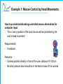
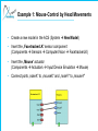
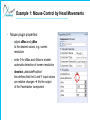
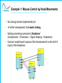
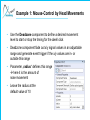
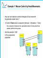
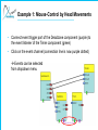
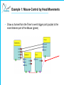
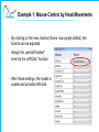
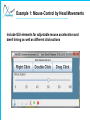
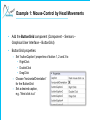
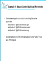
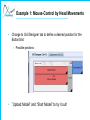
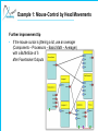
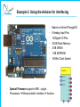
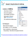
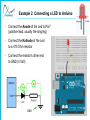
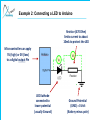
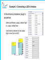
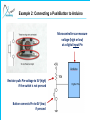
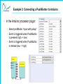
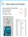
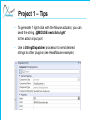
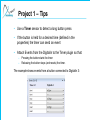
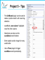
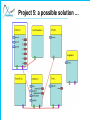
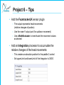
AsTeRICS Workshop – HandsOn Part Welcome !! • In this Workshop we will use the AsTeRICS System • First we make sure that everybody has ARE and ACS installed • Then we will build some easy models together • After that you can choose an Assistive Technology project and build it together in small groups The Basics • AsTeRICS can be downloaded from the official site: http://www.asterics.org • The latest source code is available at GitHub https://github.com/asterics/AsTeRICS • ACS is the graphical editor, which sends models with connected plugins to the ARE (the runtime environment) • Documentation is avaliable: – User Manual with step-by-step model creation guide – Developer manual for creating new plugins – Use F1 in ACS when plugin is selected to display plugin-help ! • Let‘s start ACS and ARE and have a look ! Some useful plugins – short examples: • Sensors – – – – – ComputerVision: FaceTrackerLK Generic: DigitialIn, AnalogIn GUI: ButtonGrid, Slider, Cellboard IntertialMeasurement: Acceleration Simulation: SignalGenerator, Timer • Processors • Actuators – Audio: WavePlayer, SpeechSyntheziser – GenericOutput: DigitalOut – GUI: Oscilloscope, BarDisplay, EventVisualizer – HomeControl: FS20, IRTrans – InputDeviceEmulation: Mouse, Keyboard – Audio&Voice: Speechprocessor – BasicMath: MathEvaluator, Threshold, Averager, Constant Dispatcher, Comparator, Differentiate / Integrate – DataConverters: IntToString – SignalShaping: Deadzone, SignalTranslate – Event&StringProcessing: StringDispatcher * Needs dedicated HW – Microcontroller: Arduino or SW / driver – OSKA – SignalPathways: PathSelector Example 1: Mouse-Control by Head Movements • In this example we will show how you can control the mouse cursor via head movements • We use a webcam and the FacetrackerLK sensor plugin (which tracks face movements) • Mouse clicks are generated via a period of inactivity (no movements) Note: you find a similar description in the AsteRICS User manual Example 1: Mouse-Control by Head Movements How to provide headtracking-controlled mouse alternatives for computer input • The x- and y-position of the local mouse will be controlled by the user‘s head movement Requirements: • A webcam Remarks: • Camera position directly in front of the user, distance 70-120cm • No other persons face should be in the field-of-view of the camera Example 1: Mouse-Control by Head Movements • Create a new model in the ACS (System New Model) • Insert the „FacetrackerLK“ sensor component (Components Sensors ComputerVision FacetrackerLK) • Insert the „Mouse“ actuator (Components Actuators Input Device Emulation Mouse) • Connect ports „noseX“ to „mouseX“ and „noseY“ to „mouseY“ Example 1: Mouse-Control by Head Movements • Mouse plugin properties: – adjust xMax and yMax to the desired values, e.g. screen resolution – enter 0 for xMax and yMax to enable automatic detection of screen resolution – deselect „absolutePostition“ this defines that the X and Y input values are relative changes fits the output of the Facetracker component Example 1: Mouse-Control by Head Movements • Mouse plugin, Input Port rider: – Select „Synchronize Inputs“ option in the Input Port Riders for both inputs (mouseX and mouseY) this will wait for both input coordinates to arrive before the mouse position is updated • You can try out your model by uploading it to the ARE and clicking „Start Model“ Example 1: Mouse-Control by Head Movements • No clicking function implemented yet • further development: Add dwell clicking • Adding processing component „Deadzone“ (Components – Processors – Signal Shaping – Deadzone) • Connect noseX/noseY outputs of the FacetrackerLK to the inX/inY inputs of the Deadzone Example 1: Mouse-Control by Head Movements • Use the Deadzone component to define a desired movement level to start or stop the timing for the dwell click • Deadzone component fade out x/y signal values in an adjustable range and generate event trigger if the x/y values are in- or outside this range • Parameter „radius“ defines this range here it is the amount of nose movement • Leave the radius at the default value of 10 Example 1: Mouse-Control by Head Movements • Default value 10 – movement range is set to 10 pixels from previous to current position • Select „Synchronize Inputs“ option in the Input Port Riders of the Deadzone plugin for inX and inY Example 1: Mouse-Control by Head Movements • How can we measure a certain timespan of low movement (to generate a dwell click) ? • Insert a Timer sensor component (Sensors – Simulation – Timer) – this component measures time, generates events if a time period has passed, perfoms timing loops • Set time-period to 1000 in the components properties Example 1: Mouse-Control by Head Movements • Connect event trigger port of the Deadzone component (purple) to the event listener of the Timer component (green) • Click on the event channel (connection line is now purple dotted) Events can be selected from dropdown menu Example 1: Mouse-Control by Head Movements • Select „enterZone“ event for the „start“ function • Select „exitZone“ event for the „stop“ and „reset“ function – These event connections control the Timer components – If nose movements stay below selected level of 10 pixels, the Timer is started – Else, the Timer is resetted to 0 and stopped – If the movement stays low for the full time period, the timer will generate its „periodFinished“ event. Example 1: Mouse-Control by Head Movements • Draw a channel from the Timer‘s event trigger port (purple) to the event listener port of the Mouse (green) Example 1: Mouse-Control by Head Movements • By clicking on the new channel (line is now purple dotted), the Events can be adjusted • Assign the „periodFinished“ event to the „leftClick“ function • After these settings, the model is usable and provides left-click Example 1: Mouse-Control by Head Movements Include GUI elements for adjustable mouse acceleration and dwell timing as well as different click-actions Example 1: Mouse-Control by Head Movements • Add a Slider component (Components – Sensors – Graphical User Interface – Slider) • Slider properties: – range of value can be defined (we can leave it at 0-100) – set slider’s component name to “Mouse Speed” – set minorTickSpacing to “10” Example 1: Mouse-Control by Head Movements • To modify the x/y mouse speed with the slider’s values, a MathEvaluator processing component is needed (Components - Processors – Basic Math – MathEvaluator) • First, the x-signal is modified: – Delete port connection from noseX to mouseX – Draw new port connection from “value” (Slider) to “inA” (MathEvaluator) – Draw new connection from noseX (Facetracker) to “inB” (MathEvaluator) – Draw a new connection from output port (MathEvaluator) to mouseX input port Example 1: Mouse-Control by Head Movements • MathEvaluator properties: – Adjust “expression” property of the MathEvaluator – this defines what will be done with the inputs – in our case we will multiply inA and inB – Slider position <50 shall slow down mouse speed, slider positions >50 shall increase mouse speed a/50*b Example 1: Mouse-Control by Head Movements • For modifying the y-signal, copy and paste (Ctrl+C & Ctrl+V) the MathEvaluator • New connections as for the x-direction: – Delete port connection from noseY to mouseY – Draw new connection from “value” (Slider) to “inA” of the second MathEvaluator – Draw new connection from noseY (Facetracker) to “inB” of the second MathEvaluator – Draw a new connection from output port of the second MathEvaluator to mouseY input port Example 1: Mouse-Control by Head Movements Example 1: Mouse-Control by Head Movements Adding different mouse click activities via GUI by • adding a ButtonGrid – to select next click type • informing mouse element about the next desired mouse click – by sending an “action string” to the Mouse element Action strings contain commands which are understood by a number of specialized actuator elements. These string contain the addressed component and the desired command e.g. “@MOUSE:nextclick,right” Example 1: Mouse-Control by Head Movements • Add the ButtonGrid component (Component – Sensors – Graphical User Interface – ButtonGrid) • ButtonGrid properties: – Set “buttonCaption” properties of button 1, 2 and 3 to • RightClick • DoubleClick • DragClick – Choose “horizontalOrientation” for the ButtonGrid – Set a desired caption, e.g. “Next click is a” Example 1: Mouse-Control by Head Movements • Add the StringDispatcher component (Component – Processors – Event and String Processing – StringDispatcher) – Translates incoming events into outgoing strings – If buttons are pressed, desired actions strings are generated for the Mouse components • Connect event trigger port of ButtonGrid (purple) to the event listener port of the StringDispatcher (green) • Click on the event channel and attach – button1 to dispatchSlot1 – button2 to dispatchSlot2 – button3 to dispatchSlot3 Example 1: Mouse-Control by Head Movements • Define the strings for slot1-slot3 in the StringDispatcher properties: – slot1(button1): “@MOUSE:nextclick,right” – slot2(button2): “@MOUSE:nextclick,double” – slot3(button3): “@MOUSE:nextclick,drag” • Connect output port of the StringDispatcher to the “action” input port of the mouse Example 1: Mouse-Control by Head Movements • Change to GUI Designer tab to define a desired position for the ButtonGrid – Possible positions: • ”Upload Model” and “Start Model” to try it out! Example 1: Mouse-Control by Head Movements Further improvement tip • If the mouse cursor is jittering a lot, use an averager (Components – Processors – Basic Math – Averager) with a BufferSize of 5 after Facetracker Outputs Example 1: Mouse-Control by Head Movements Example 2: Using the Arduino for interfacing • • • • • • • • • Based on Atmel ATmega328 6 Analog Input Pins 14 Digital I/O Pins 32 KB Flash Memory 2 KB SRAM 1 KB EEPROM 16 MHz Clock Speed Special Firmware supports ARE – plugin Processors Microcontroller Interface Arduino Example 2: Using the Arduino for interfacing • Installation of COM Port: – Attach Arduino to USB Port – Driver must be updated in Device manager to get COM Port – Select location of „Arduino.inf“ (folder: CIMs/Arduino/driver) – Click „Install this driver software anyway“ • For Windows 8: Reboot without Driver Signature: Enter „shutdown /r /o /f /t 00“ in shell-window Choose: troubleshooting -> advanced options -> startup settings -> reboot without driver signature enforcement See: http://www.makeuseof.com/tag/how-can-i-install-hardware-with-unsigned-drivers-in-windows-8/ Example 2: Using the Arduino for interfacing • Breadboard connections – – – – allow flexible building test circuits the bars are connected vertically the rails are connected horizontally use cables to connect components and Arduino Pins Example 2: Connecting a LED to Arduino • Connect the Anode of the Led to Pin7 (positive lead, usually the long leg) • Connect the Kathode of the Led to a 470 Ohm resistor • Connect the resistor‘s other end to GND (0 Volt) GND Example 2: Connecting a LED to Arduino Resistor (470 Ohm) limits current to about 10mA to protect the LED Microcontroller can apply 5V (high) or 0V (low) to a digital output Pin LED Kathode connected to lower potential (usually Ground) Ground Potential (GND) = 0 Volt (Battery minus pole) Example 2: Connecting a LED to Arduino • In the Arduino processor plugin‘s properties: – Define pin7Mode „output, default high“ or „output, default low“ – Use Events Listeners to set output high or low (turn on/off) Example 2: Connecting a PushButton to Arduino • Connect one side of switch to GND and the other side to Pin 3 • When switch is pressed: all 4 leads connected ! Example 2: Connecting a PushButton to Arduino Microcontroller can measure voltage (high or low) at a digital input Pin Resistor pulls Pin-voltage to 5V (high) if the switch is not pressed Button connects Pin to 0V (low) if pressed Example 2: Connecting a PushButton to Arduino • In the Arduino processor plugin: – Select pin3Mode: “input with pullup” – Event is triggered when PushButton is pressed (high -> low) – Event is triggered when PushButton is relesed (low -> high) Example 2: Switching a Led with a Pushbutton • • • • Switch is connected to Pin3 (internal PullUp) LED is connected to Pin7 Switch Open LED on Switch Closed LED off Example 2: Switching a Led with a Pushbutton Example 2: Reading Analogue Values • Connect a Potentiomenter – Right lead goes to 5 V – Middle lead goes to A0 – Left leads goes to GND • Voltage at A0 will vary from 0V to 5V when turning Example 2: Reading Analogue Values • Arduino Analog-Digital Converter – 10 bit 1024 Values – Zero Volt = Value 0 – 5 Volt = value 1023 • Important: Set periodicADCUpdate to a positive Time (in miiliseconds) otherwise the ADC is off !!! Example 2: Reading Analogue Values 0 A voltage divider with a resistive sensor (e.g. LDR – Light dependent resistor) could also be a force sensor, temperature sensor etc. Try: to print the brightness value in the ARE Window ! Example 2: Reading Analogue Values • Read a resistive sensor: – build a voltage divider! – R1 depends on the Sensor Example 2: Control Led with Sensor • Try: Switch LED on if Sensor value reaches threshold Example 2: Control Led with Sensor Hands-On Projects HANDS ON !! • Select a project and solve it in small groups ! • We have some sets of hardware which can be used • 6 Project topics are available Project 1: Digitally controlled Mouse • Realize a fully working mouse with 3 push buttons – 2 buttons: left/right or up/down pressing both buttons: selection of axis (X or Y) – 1 button: mouse click short press: left click long press: right click Project 2: Analog-controlled Mouse • Realize a fully working mouse with 2 push buttons and 1 potentiometer – potentiometer: cursor movement with 2 directions (e.g. +x, -x) – 1 button: toggle axis (X or Y) – 1 button: mouse click short press: left click long press: right click Project 3: Virtual Keyboard • Realize a keyboard with scanning via the Acceleration Sensor and/or EMG input – Use OSKA with a keyboard grid for writing – Use automatic scanning for key selection – Use EMG sensor for controlling the scanning • Minimal muscle movement selects key Project 4: Environmental Control • Realize an environmental control system – Speech Recognition input – FS20 for controlling a 220V light – Abotic door opener connected via GPO module Project 5: Infrared Control • Control a GhettoBlaster via IR device – GUI (Cellboard) with automatic scanning – IR Trans for infrared remote control – Send commands to HiFi Stereo Radio: • • • • On/Off Play / Stop Volume control Next/Previous song Project 6: Accessible Pong Game • Realize a Pong Game Interface via desired input sensors – Player 1: – Player 2: uses Accelerometer: tilting controls paddle 1 uses WebCam / FaceTracking: up/down movement of head controls paddle 2 Project 1 – Tips • Connect 3 buttons to your DigitalIn as shown: • Alternatively, you can use an Arduino and use 3 pushbuttons Project 1 – Tips • To generate 1 right-click with the Mouse actuator, you can send the string „@MOUSE:nextclick,right“ to the action input port • Use a StringDispatcher processor to send desired strings to other plugins (see HeadMouse example) Project 1 – Tips • Use a Timer sensor to detect a long button press • If the button is held for a desired time (defined in the properties) the timer can send an event • Attach Events from the DigitalIn to the Timer plugin so that: – – Pressing the button starts the timer Releasing the button stops (and resets) the timer. The example shows events from a button connected to DigitalIn 3: Project 1 – Tips • Use a ConstantDispatcher processor to create movement: – Send negative value (-1) to Mouse actuator x/y for up/left – Send positive value (1) to Mouse actuator x/y for right/down Project 1 – Tips • Dispatch up/left or right/down movement via connected pushbuttons (here: DigitalIn Pins) Project 1: a possible solution … Project 2 – Tips Project 2 – Tips • Different value ranges of mouse movement and Arduino ADC: – Mouse: relative, positive and negative values – ADC: absolute, only positive values (0-1023, 12bit) • Solution: SignalTranslation plugin Project 2 – Tips • It‘s hard to find the exact centre of the potentiometer – > the Cursor is always moving • We need a window around the centre, where the cursor does not move: – > Deadzone plugin Project 2: a possible solution …. Project 3 – Tips • Connect the EMG shield to the Arduino – Attach electrodes to forearm • Use an Arduino plugin to view analog values of AD0 – Select an update rate of 5ms (200Hz) for the Arduino ADC • Use oscilloscope to view raw singal (try it out !) Project 3 – Tips • To calculate the EMG force: – With a Differentiate processor you to get rid of the DC-offsets and slow changes in the EMG signal. (You can also experiment with the Filter Plugin) – use a MathEvaluator to get the absolute values of the signal enter abs(a) as expression in the MathEvaluator properties – use an Averager to calculate the average of 30 samples • Use a Threshold processor to create events if the EMG force exceeds a certain level – Check reasonable values with oscilloscope or BarDisplay Project 3 – Tips • Add a „OSKAInternalScanning“ plugin – this launches the OSKA on-screen keyboard in automatic scanning mode – Upload model to ARE (to update list of available keyboards) – Select an appropriate keyboard grid for writing for example: „keyboards\writing\abc.xml“ – Select scan speed 4 and highlightStyle „InvertKeys“ Project 3: a possible solution … Project 4 – Tips Requirements: • Abotic Door Opener – http://abotic.com/en/ – DigitalOut module – Plug In Abotic Door Remote to DigitalOut port 1 • Voice recognition – Microphone (Check signal level!!) – Microsoft Speech Platform Server version 11, the SR language and the TTS language pack must be installed too. – http://www.microsoft.com/enus/download/details.aspx?id=27225 • FS20Sender device – http://www.elv.at/fs20-funkschaltsystem.html Project 4 – Tips Check the signal level of the microphone! Select the recognition language. In the mode „always active“ the recognition is performed continuously. command1-commandN: Enter voice commands Project 4 – Tips • The DigitalOut plugin expects action strings: "set", "clear", "toggle" and "press". The command has to be followed by a comma and the port number, for example: – "@DIGITALOUT:set,1" or – "@DIGITALOUT:toggle,2“. – The "press"-command toggles the given output port two times with a delay of 500ms. • StringDispatcher can be used to construct the string. Project 4 – Tips • Enter the housecode and address of the target device in the FS20Sender properties. • Our FS20Receiver Power Switch is already configured to housecode 11111111 and address 1111 Project 4 – Tips • In the event editor of FS20Sender map recognized commands with FS20 actions: – off: Switch off device – onLevel1-onLevel16: Switch on device to a certain level – toggle: Toggles switching (on/off) Project 4: a possible solution … Project 5 – Tips Requirements: • Arduino – Connect push button as shown in Arduino slides, use internal pullup resistor • IRTrans device – Install IRTrans driver and SW from http://www.irtrans.de/de/download/windows.php – Copy “asterics.rem” remote configuration file to C:\ProgramData\IRTrans\remotes – Start IRTransServer.exe – Right click on IRTrans symbol in system tray and choose “Startup Parameter” – Select “USB” and “Save & Restart” Project 5 – Tips • Test sending IR codes – – – – – Right click on IRTrans symbol in system tray Select “Send IR Code” Select “asterics” as remote configuration Select a command Click on “Send” Project 5 – Tips • The CellBoard plugin can be used to make a „button-matrix“ with scanning selection. • scanMode „row-column“ highlights rows first, then colums • Selections are done via the scanSelect event listener. • Enter caption and/or image for every used button • Use a Timer plugin to trigger scanMove events periodically. Project 5 – Tips • Use default hostname and port to connect to the local IRTrans • prestring selects the remote control configuration to use, note the comma at the end !! • send1-sendN: Enter the configured / stored IR codes Project 5: a possible solution … Project 6 – Tips • Add the Ponggame actuator and select the mode „position“ – Input values of 0-300 are accepted for the paddles – The output of the used sensors must be adjusted to match this range of 0 – 300 to control the paddles – A „start“ event must be connected; this event could be generated via a GUI element ( eg. ButtonGrid plugin) • Add an Accelerometer sensor for paddle1 – Use a SignalTranslation processor to map the range of the yAcc output (-8192 – 8192) to (0 – 300) Project 6 – Tips • Add the FacetrackerLK sensor plugin – The output represents head movements (relative changes of postion) – Use the nose-Y output port (for up/down movement) – Use a MathEvaluator to invert/scale the movement values as desired • Add an Integration processor to accumulate the relative changes of the head movements – This creates an absolute position for the paddle 2 control – Set upperLimit and lowerLimit of the Integrator to 300/0 Project 6: a possible solution …