1
User Manual
AsTeRICS User Manual
Page 1
Table of Contents
1
2
3
Introduction .......................................................................................................... 5
1.1
AsTeRICS System Overview ................................................................................... 5
1.2
Intended Audience .................................................................................................. 7
1.3
Software Installation ................................................................................................ 8
1.4
Starting ARE and ACS ............................................................................................ 9
1.5
Possible Applications: An Outlook ..........................................................................10
First steps with the AsTeRICS Software ............................................................ 11
2.1
ARE – The AsTeRICS Runtime Environment .........................................................11
2.2
ACS – The AsTeRICS Configuration Suite .............................................................12
2.2.1
Basic model creation concepts ........................................................................12
2.2.2
ACS Basic Functions.......................................................................................13
2.2.3
Create and Edit a Model ..................................................................................13
2.2.3.1
Model Manipulation via Mouse .................................................................14
2.2.3.2
Model Manipulation via Keyboard.............................................................14
2.2.4
Open and Save Models ...................................................................................15
2.2.5
Connecting the ARE and Managing Models ....................................................15
2.2.6
Connection Modes ..........................................................................................16
2.2.7
The Edit Tab ...................................................................................................18
2.2.8
Component Context Menu...............................................................................19
2.2.9
Ports, Channels and Data Types .....................................................................19
2.2.10
Events .............................................................................................................20
2.2.11
Adjusting Properties of a Component ..............................................................21
2.2.11.1
Dynamic Properties and their Use ............................................................21
2.2.11.2
Synchronization of Input Ports..................................................................22
2.2.12
Action Strings ..................................................................................................23
2.2.13
Grouping and Ungrouping Elements ...............................................................24
2.2.14
The GUI Designer ...........................................................................................25
2.2.15
Status Reporting and Error Logging ................................................................26
2.2.16
Component Collection Manager ......................................................................26
2.2.17
Further ACS Options .......................................................................................27
Plugins: The Elements of AsTeRICS Models ..................................................... 28
AsTeRICS User Manual
Page 2
4
Step-by-Step Guide to AsTeRICS Model Creation ............................................ 29
4.1
Making a first Model: Using Ports, Events and Properties ...................................29
4.2
A Model for Mouse-Control by Head Movements ................................................33
4.2.1
Extending the Head-Mouse: Add Dwell Clicking ..............................................35
4.2.2
Extending the Head-Mouse: Adjustable Parameters via GUI elements ...........37
4.3
Using Standard Input Devices ................................................................................41
4.3.1
Mouse-Click Alternatives via Buttons of a Gamepad .......................................41
4.3.2
Joystick-based Mouse replacement ................................................................42
4.4
Game Control and Making Games Accessible .......................................................43
4.4.1
PC Input Emulation for Games using Keyboard ..............................................44
4.4.2
PlayStation 3 Control and HID Device Emulation ............................................45
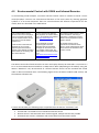
4.5
Environmental Control with OSKA and Infrared Remotes .......................................46
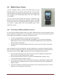
4.6
Mobile Phone Control .............................................................................................49
4.6.1
Controlling a Windows Mobile 6.5 phone.........................................................49
4.6.2
Controlling an Android Phone..........................................................................50
4.7
Working with Bioelectric Signals: the Enobio BNCI Recording Unit .....................52
4.7.1
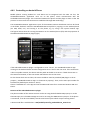
Display Enobio Signals and Verify the Signal Quality ......................................53
4.7.2
Blink Detection to create Mouse Clicks............................................................54
4.8
5
OSKA – The On-Screen Keyboard Application .................................................. 56
5.1.1
OSKA Keyboard ..............................................................................................56
5.1.2
The OSKA Editor .............................................................................................57
5.1.3
The OSKA Settings editor ...............................................................................58
5.1.4
Using Word Prediction and the Communicator Line ........................................59
5.2
6
Other interesting models and system capabilities ...............................................55
Using OSKA Keyboard together with the ARE........................................................60
5.2.1
Sending Action Strings to the ARE ..................................................................61
5.2.2
Customizing OSKA Keyboard Templates ........................................................62
AsTeRICS Hardware.......................................................................................... 63
6.1
6.2
The AsTeRICS Personal Platform ......................................................................63
Custom Interface Modules and Sensors .................................................................65
6.2.1
Display options for the Personal Platform ........................................................66
6.2.2
The Universal HID Actuator .............................................................................67
6.2.3
Eye Tracking Support ......................................................................................68
6.3
Supported “Off-The-Shelf” Devices and Standards.................................................69
AsTeRICS User Manual
Page 3
6.4
6.4.1
Sensor Scenarios ............................................................................................70
6.4.2
Actuator Scenarios ..........................................................................................71
6.5
7
8
Application Scenarios using AsTeRICS hardware ..................................................70
Featured Models and Applications .........................................................................71
6.5.1
Accelerometer-Controlled Mouse ....................................................................71
6.5.2
Five-Switch Mouse with Voice Feedback ........................................................72
6.5.3
Blow-Sensor Controlled Mouse .......................................................................72
6.5.4
Flex-Sensor Controlled Mouse ........................................................................73
6.5.5
Enobio based Brain Computer Interface for OSKA Control..............................73
Additional Tools and Software ........................................................................... 74
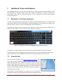
7.1
Windows-7 On-Screen keyboard ............................................................................74
7.2
Point-N-Click ..........................................................................................................74
7.3
Input Benchmark ....................................................................................................75
7.4
Crosshair 1.1 ..........................................................................................................75
Troubleshooting and Solving Problems.............................................................. 76
8.1
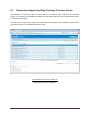
Community Support and Bug Tracking: The User Forum .......................................77
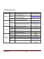
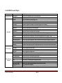
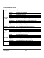
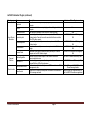
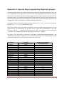
Appendix A: Summary of available Plugins .............................................................. 78
A.1 AsTeRICS Sensor Plugins ......................................................................................78
A.2 AsTeRICS Processor Plugins .................................................................................80
A.3 AsTeRICS Actuator Plugins ....................................................................................82
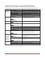
Appendix B: Summary of supported Action Strings .................................................. 84
Appendix C: Special Keys supported by Keyboard plugins ...................................... 85
Appendix D: The AsTeRICS Consortium .................................................................. 87
AsTeRICS User Manual
Page 4
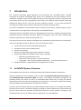
1
Introduction
The “Assistive Technology Rapid Integration and Construction Set” (AsTeRICS) offers a flexible
framework for Assistive Technologies (AT), which can be adapted to the motor abilities of users.
AsTeRICS is intended to ease access to different devices such as personal computers, cell phones and
smart home devices via one single platform which offers many different input methods. One input
method that works well for a user may be used in different contexts – e.g. the same method for
accessing the computer mouse function may be used to operate the home stereo.
The various capabilities of the AsTeRICS system include PC input device emulation, game control,
environmental control applications and utilization of embedded devices.
AsTeRICS provides an affordable system for developing user driven AT by combining emerging sensor
techniques like Brain-Computer Interfaces (BNCI) and computer vision with basic actuators (like
switches, sip/puff sensors, special mice/joysticks, etc.).
This manual covers the user aspects of AsTeRICS and is dedicated to people who want to understand
and use the provided systems components. The covered topics include:
1.1
An overview of the system and possible applications
Installation and first start of ARE and ACS
Sensors and Actuators
Running and adjusting existing system models via the ACS
Step-by-Step Guides to AsTeRICS model creation, including:
o Webcam-controlled mouse cursor
o Game Control via keystroke- or joystick emulation
o Using OSKA – the On Screen Keyboard Application – for Environmental Control
AsTeRICS hardware, supported devices and application scenarios
AsTeRICS System Overview
The AsTeRICS system consists of a software framework and optional hardware components.
Software components of the AsTeRICS system include the AsTeRICS Configuration Suite (ACS) and
the AsTeRICS Runtime Environment (ARE). The ACS is a PC-software for graphical configuration of
AsTeRICS models. This means: the ACS is a comfortable editor which lets you setup your desired
functionality without the need for programming the computer on a low level. It allows the selection
of desired plugins and the adjustment of important parameters.
The ARE is the environment where the created AsTeRICS models actually run: It provides the assistive
functions like the sensor- and actuator plugins according to system model which has been defined in
the ACS. Sensor values are acquired, processed and utilized to control actuators according to the
AsTeRICS model. Thus, many different assistive applications can be established.
AsTeRICS User Manual
Page 5
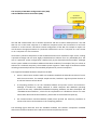
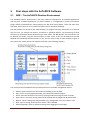
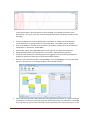
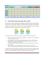
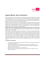
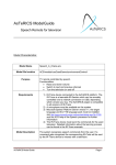
The interplay of AsTeRICS Configuration Suite (ACS)
and AsTeRICS Runtime Environment (ARE):
AsTeRICS
Configuration Suite
ASAPI Client
ASAPI Server
AsTeRICS Runtime Environment (Java/OSGi)
Enobio
plugin
Signal
processing
plugin1
Signal
processing
plugin2
Signal
processing
plugin2
SVM
Plugin
ACS and ARE communicate over a network connection and the so-called “ASAPI protocol”. ACS and
ARE can run on the same computer or on different computers which are connected to a local area
network or via the internet. This allows remote configuration of the ARE, for example an expert can
use the ACS to change parameters of a particular model which runs on a computer at a user’s home
or on a computer in a care institution.
All necessary software components of the AsTeRICS framework are available as open source, making
it possible to design and use novel, highly individualized AT solutions for a very affordable price. The
cost of a particular system configuration is defined only by the desired hardware modules. Although
certain system models work without additional hardware modules (for example if they use a built-in
webcam of a notebook computer), the AsTeRICS system supports a wide range of hardware modules
including customized I/O devices and standard peripherals for personal computers.
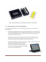
The supported AsTeRICS hardware components include:
Sensor- and actuator modules which are needed to establish the desired interaction of a user
with the environment, for example simple switches, bioelectric signal acquisition devices or
an infrared remote control device.
A computing platform to run the AsTeRICS software and process sensors and actuators.
Although a standard PC, Laptop, Netbook or Tablet computer with Windows operating
system can be used, a dedicated embedded computing hardware has been developed: the
“AsTeRICS Personal Platform”, which fits the requirements of a flexible AT device. For more
Information about the Personal Platform, please refer to the hardware chapter (6).
The Communication Interface Modules (CIMs) which provide the necessary interfaces to
connect the sensors and actuators to the computing platform.
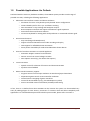
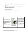
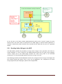
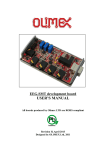
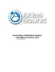
The following figure illustrates how the AsTeRICS hardware and software components establish
alternative interfaces between users and their environment/devices/services:
AsTeRICS User Manual
Page 6
AsTeRICS hardware components, interfacing the user with environment and services
If desired, a complete AsTeRICS setup (including hardware, software and desired application models)
can be packaged and tailored by selected AsTeRICS distributors (please refer to the AsTeRICS
homepage for details).
1.2
Intended Audience
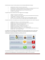
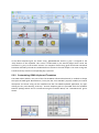
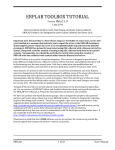
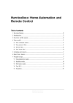
Due to the vast possibilities of the AsTeRICS framework, different target groups are addressed: The
spectrum ranges from end-users who utilize one or several pre-configured system setups for their
needs, over caretakers and therapists who work with the ACS software to adjust parameters of those
system setups individually for a person, to AT-professionals and IT-developers who modify or extend
the AsTeRICS system software or hardware by using the provided developer documentation:
Needed IT - Knowledge
LOW
Primary User
Caretakers
Uses tailored models,
Uses Easy ARE GUI
to select or adjust
model parameters
No ACS use
Help in sensor
adjustment, ARE startup,
Easy GUI adjustment and
model selection
No ACS use
AsTeRICS User Manual
HIGH
Therapists /
Care Professionals
AT professionals
with IT background
IT developers /
researchers
Choose and tailor
existing models,
Reduced ACS use
Extendend ACS use,
Model creation and
extension
ARE plugin
development
ACS model creation
Page 7
1.3
Software Installation
The following steps describe how the AsTeRICS software framework can be installed on a PC with
Windows operating system. (This is an alternative to purchasing the complete AsTeRICS personal
platform that includes all software installations).
Download the AsTeRICS setup executable from:
http://www.asterics.eu/download/AsTeRICS_setup.exe
Start the setup executable – you will be guided through a number of dialogs which allow
specifying the destination path and Start-Menu entries.
The setup software automatically installs needed prerequisites on your system. These include
the .NET 4.0 framework by Microsoft, the Microsoft Redistributable package for VS2010 and
the Java Runtime Environment (JRE) Version 7.
If desired, the installation of the JRE can be disabled. This is useful if JRE Version 7 (32-bit) is
already installed on your computer.
Please note that the 32-bit version of JRE is needed also if you have a computer running the
64-bit version of Windows. You may install the 32-bit version using the AsTeRICS installer in
this case (it is only copied to a local folder and does not influence other JRE installations).
If you have problems with the installation, please refer to the Quick-Start guide:
http://www.asterics.eu/download/QuickStart.pdf
AsTeRICS User Manual
Page 8
1.4
Starting ARE and ACS
After the AsTeRICS setup has finished, icons for starting the Configuration Suite (ACS) and the
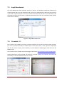
Runtime Environment (ARE) have been created on the desktop. Start the ARE by doubleclicking “ARE.exe” in the ARE folder. When your operating system’s firewall asks if the TCP
Port connection should be allowed, grant the rights for connection. If the ARE’s startup
screen does not come up as shown in the figure below, make sure that the Java “/bin” folder
is in the system path (see http://www.java.com/en/download/help/path.xml)
Now try to start the ACS by double clicking “ACS.exe” (the initial startup may take a while). The
following figure shows the ACS window after startup:
ARE and ACS are running: You are ready to use the AsTeRICS system !
What Next ?
The ARE autostart model features some small model demos which work without special hardware –
they can be accessed with the “star Demo” button. You could also browse the provided model demos
using the ACS: Open a model from the folder “ACS/models”, connect to the ARE, upload the model
and start it. These steps will be described in the following chapter. Refer to the ACS help (press F1 in
the ACS application) for detailed descriptions of the sensor- processor- and actuator plugins.
Most of the functional models need additional sensor- and actuator hardware (see application
scenarios in chapter 6.4. A model’s purpose and hardware requirements can be provided in the
Model Description Dialog (ACS main menu → Edit → Show Model Description) – although it depends
on the author of a particular model if this description is available.
AsTeRICS User Manual
Page 9
1.5
Possible Applications: An Outlook
Combined with the necessary hardware modules, the AsTeRICS system provides a wide range of
possible use cases, including the following applications:
Alternative User Interface creation and device emulation
o Emulation of mouse- or keyboard input by desired sensor configurations
o Camera-based input for face- eye- and feature tracking
o Gaze estimation via eye tracking and head pose analysis
o Brain Computer Interfaces and support of bioelectric signal acquisition
o Sensor data fusion and feature selection
o On-Screen Keyboard for writing with word prediction or customized selection grids
Environmental Control
o Easy interfacing with KNX (Konnex)
o Support of Infrared Remote Control code recording and replay
o FS20 support for affordable home automation
o Smart phone accessibility for Android and Windows-Phone devices
Control of mechanic actuators or external appliances
o Pneumatic Gripper actuator for mouthsticks
o Generic control via control voltages or Relais
o Door-Opener control (e.g. the Abotic door opener)
Voice Interaction
o Speech control for selection of functions and home automation
o Synthetic voice feedback
Game control & Creativity support:
o PC-game control via local input emulation or HID device/joystick emulation
o PlayStation3 game control via PS3-controller emulation
o Custom button remapping of game controllers
o Control of IR-controlled toys (e.g. the RoboSapien toy robot)
o Sensor controlled musical instruments (via Midi) and drawing
In fact, there is no defined limit what AsTeRICS can do, because the system can be extended very
easily by adding plugins for new sensors, processors or actuators which will allow completely new
applications. For a detailed description how to build system models, please refer to section 4.
AsTeRICS User Manual
Page 10
2
First steps with the AsTeRICS Software
2.1
ARE – The AsTeRICS Runtime Environment
The AsTeRICS Runtime Environment is the basic software framework for all AsTeRICS applications
and use-cases. AsTeRICS applications (so called “models” or “configurations”) consist of functional
plugins which provide different functionalities. The ARE hosts these plugins, starts and stops their
operation, allows them to run in parallel and takes care for their data exchange.
The ARE provides a main panel (the “ARE Desktop”) for plugins to display information or to interact
with the user, for example via buttons, text-boxes or graphical displays. The positioning of these
elements can be defined inside the ACS using a visual editor. The ARE Window size and position can
be defined per-model, using the ACS GUI editor as well. There, it can also be defined if the ARE
Window uses Window/Frame decorations or not, and if it stays on top of other windows or goes to
the system tray. (These options are explained in detail in the following chapter).
The control panel of the ARE window provides quick access to model management actions:
Deploy: allows selection of a local model and loading it into the ARE.
Start: runs a currently deployed model, starts data-flow between plugins.
Pause: stops the data flow of a currently running model preserving the state of model.
Stop: causes a currently running model to be stopped and the plugins will be deactivated.
Options: opens a dialog with ARE parameters (e.g. background color) and “About” infos.
Quit: stops a running model and shuts down / closes the ARE.
Status/log display: opens a window showing recent logging/error messages
AsTeRICS User Manual
Page 11
2.2
ACS – The AsTeRICS Configuration Suite
The AsTeRICS Configuration Suite (ACS) allows design of models (configurations) for the ARE. Beside
the model creation and manipulation capabilities, the ACS also allows model download and upload to
the ARE as well as starting and stopping deployed models inside the ARE. Furthermore, status
reports, failure messages and logging from the ARE can be displayed. The ACS might run on the same
computer as ARE, or on another computer system.
2.2.1 Basic model creation concepts
For creating AsTeRICS models, some basic concepts need to be well understood. Thus some
important terms will be explained in the following:
Model - is a set of components and their interconnection, defining the operation of the
AsTeRICS Runtime Environment. The model includes information on how to react to
signals from sensors, and how to perform actions using the connected actuators.
A less technical explanation would be: a model is a definition of the way to translate data
from sensors (like switches, cameras, a mouse, joystick etc.) to actuators (door openers,
TV remote control, computer cursor movements etc.).
A model representation in the ACS consists of graphical elements identifying the
components and their connections (channels).
Components (a.k.a Plugins) are pieces of software that perform calculations or
communicate with hardware devices. For example: to use a simple on-off switch in a
model, the ARE needs an appropriate plugin. To display data on screen another plugin is
needed. To eliminate unwanted tremor from a mouse movement a plugin is needed, too.
Components can be of four types:
o sensors - used as an interface with sensor devices - thus logically are the source
of data flow in an AsTeRICS model,
o processors - used as a way to manipulate data from sensors or other processors;
processors typically need input data and can output that data to other
processors or actuators,
o actuators - used as an interface with actuator devices - the devices that execute
action wanted by an AsTeRICS user - must be driven directly or indirectly by data
from sensors,
o specials - this type is not used at the moment
Ports are used to connect the components. Ports deliver data between various
components. There are four types of ports: input, output and event listener and event
trigger ports.
Channels are the connections from an output port of a component to an input port of
another one). Eventchannels allow the connection of event triggers to event
listeners. See the following sections for detailed descriptions of channels and events.
AsTeRICS User Manual
Page 12
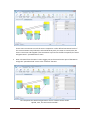
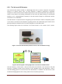
2.2.2 ACS Basic Functions
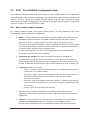
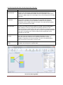
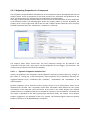
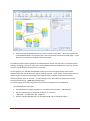
The figure below shows the main panel of the AsTeRICS Configuration Suite after the application has
started. The screen is divided in three main areas, the menu area (1), the deployment area (2) (where
the drawing will be done), the GUI drawing area (3), switchable with the deployment area and the
properties area (4), where the settings of the components can be adapted.
Additionally, the main menu will open, if the AsTeRICS-Button is pressed in the menu bar - see figure
below. All functions of the main menu are also reachable via buttons in the tabs, providing you with
System-tab, Components-tab, Edit-tab and Misc.-tab. The About button is an exception, not
producing a tab, but a dialog. This dialog shows general information about the ACS and the AsTeRICS
project.
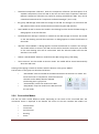
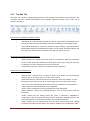
2.2.3 Create and Edit a Model
To create a new model, add one or several
components. To do so, select the tab
“Components”, and from the sub-menu select
a group of components, depending on what is
supposed to be added. The four component
groups are Sensors, Processors, Actuators and
Saved Groups. Now, this added component
can be manipulated in the drawing area. This
can be done with the functions in the Edit-tab
or directly by using the mouse or the
keyboard.
AsTeRICS User Manual
Page 13
2.2.3.1
Model Manipulation via Mouse
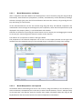
After a component has been added to the drawing field, it can be moved by using the drag and drop
functionality. Several elements (components, channels, eventchannels) can be selected by drawing a
selection rectangle (just press the left mouse button and move the mouse) or by pressing the CtrlKey and clicking on each element.
All the selected elements can be also moved using drag and drop. All selected components are
marked with a blue rectangle in the background, the component, which has the keyboard focus (and
displayed in the property editor), is surrounded with a blue border.
Channels can be drawn by pressing the mouse button over an output port and dragging the channel
to an input port. Connecting event channels is similar to the channels.
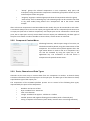
The selection of a component is shown in the figure below.
The properties of the selected component can be seen in the Property-window on the right. This
windows show the individual settings of the selected plugins, and allows to change those settings:
2.2.3.2
Model Manipulation via Keyboard
All elements within the drawing area can be set on focus, using the Tab-key or the arrow-keys. To
select an element, the Space-key has to be used, to select several elements, use Ctrl- and Space-Keys
at the same time. The App-Key opens the context menu. More information about the usage of the
keyboard within the ACS can be found in the section Component Context Menu.
AsTeRICS User Manual
Page 14
2.2.4 Open and Save Models
In the “System” tab, models can be saved on the local file system
(Save Model, Save Model as), or loaded from the local file system
(Open Model). New Model cleans up the drawing field, preparing
everything for a new model.
2.2.5 Connecting the ARE and Managing Models
In the ”System” tab, the group “ARE” handles the functionalities for connecting to and
communicating with the ARE. The connection to the ARE is handled by the AsTeRICS Application
Programming Interface (ASAPI):
The functions of the “System” tab:
•
“Connect to ARE” connects the ACS with the ARE. The “Connect to ARE” dialog appears,
asking for the connection data. The host name (IP-address of the host) can be found in
the ARE configuration, the default port should be 9090.
•
Beside this connection dialog, also auto connection can be used, see the section Options /
General Settings. When the connection has been established, two special cases can
occur:
o An active model (deployment) has been detected on the ARE. The user will be asked
to download this model or to proceed without downloading it.
o An active model (deployment) has been detected and is running on the ARE. The user
will be asked to download this model and switch the ACS to running mode or to
proceed without downloading it.
•
“Disconnect from ARE” closes the connection to the ARE.
•
“Upload Model” transmits the model in the drawing from the ACS to the ARE. The model on
the ARE will be overwritten. Uploading the model to the ARE does not start the model on
the ARE.
•
“Download Model” transmits the active model from the ARE to the ACS. The model on the
ACS drawing area will be overwritten.
AsTeRICS User Manual
Page 15
•
“Download Component Collection” loads the component collection (the description of all
available components) from the ARE to the ACS and uses these component collection.
Different component collections are useful for working with different AREs. They can be
created and selected via the “Component Collection Manager” (see 2.2.16)
•
The group “ARE Storage” deals with the storage on the ARE. The storage is an area within the
ARE where models can be stored and also activated using the ARE interface.
•
“Store Model on ARE” transmits the model in the drawing from the ACS to the ARE storage. A
dialog appears to set the filename.
•
“Load Model from Storage” transmits a model from the ARE storage to the ACS. The model
on the ACS drawing area will be overwritten. A dialog appears to select the filename of
the model.
•
“Activate a Stored Model”: A dialog appears to select the filename of a model in the storage.
This model will be set active in the ARE and also will be started. Furthermore, the model
on the ACS drawing area will be overwritten with the selected model and the ACS
switches to run-mode.
•
“Delete a Stored Model” deletes a model from the ARE storage using a file dialog.
•
“Set as Autorun” sets the model as autorun model. This model will be started automatically
when the ARE starts.
Starting and stopping a model can be done with the buttons in the group “Model”.
The functions of this group are described as follows:
•
•
•
“Start Model” starts the model on the ARE and switches the ACS into run-mode. This
means that now no components, channels and event
channels can be added, edited or deleted.
The drawing area is greyed out.
“Pause Model” pauses the model on the ARE.
“Stop Model” stops the model on the ARE and ends
the run-mode.
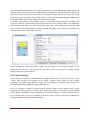
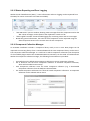
2.2.6 Connection Modes
The ACS can enter several different modes, depending on the status of the connected ARE. The
connection status is displayed at the bottom left corner of the ACS. Possible ACS modes are:
•
•
•
•
•
Disconnected
Connected
Synchronized
Running
Pause
AsTeRICS User Manual
Page 16
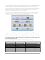
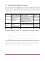
The following table describes the operating modes of the ARE:
ACS - Mode
Disconnected
Connected
Synchronized
Running
Pause
Description
This is the standard mode after the ACS has been started. The drawing area is
enabled, new components can be added and channels between the
components can be established. Models cannot be uploaded or downloaded
and also the ARE storage is not accessible, due to the fact that there is no ARE
connected.
This mode is reached after the ACS has been connected to the ARE. The
drawing area is enabled, new components can be added and channels
between the components can be established. Models can be uploaded or
downloaded, also the ARE storage is accessible. The status and the logging
file can be requested from the ARE.
After a model has been uploaded or downloaded, the ARE is synchronized with
the ACS. The model can now be started on the ARE, using the Start Model
button. Adding or removing components and editing channels or event
channels will cause a switch back to the mode connected. Changing properties
of the components will not change the mode, as these changes are transmitted
to the ARE in the background. Also the status and the logging file can be
requested from the ARE.
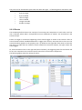
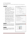
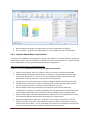
After the Start Model button has been pressed, the ACS is in the running mode.
Within this mode, the drawing area is disabled (indicated by a grey
background) and the buttons in the components tab and the edit tab are
disabled, so elements can only be selected or moved. The following figure
shows a screenshot of the ACS in running mode.
This mode is similar to the running mode, with the difference, that the model on
the ARE is not running but in a pause state.
The ACS in Running Mode
AsTeRICS User Manual
Page 17
2.2.7 The Edit Tab
The “Edit” tab is used for manipulating properties of the components and their interconnections. The
list below provides a detailed description of the available operations found on the “Edit” tab as
shown in the figure.
Description of the Model Properties Group:
•
•
“Edit Model ID” edits the unique model ID. This ID is generated automatically and is
used by the ARE to store model based information belonging to the editing model.
“Show Model Description” shows the model description dialog. A Short Description,
Model Requirements and Detailed Description can be edited. These descriptions are
saved with the model and are available in the ARE as a help for the user.
Description of the Edit Components Group:
•
•
“Move Component” enables the move mode of a component. Now the component
can be moved around the drawing board using the arrow keys. Using the Enter-key
or tabbing to another component ends the move mode.
“Component Properties” shows the properties of the component.
Description of the Edit Group:
•
•
•
•
•
•
•
•
“New Channel” indicates that a channel is about to be drawn. To start drawing a
channel, click on an output port or use the context menu.
“New Eventchannel” indicates that an event channel is about to be drawn. To start
drawing an event channel, click on an event trigger port or use the context menu.
“Cut” cuts out the selected elements and stores the cut elements in the clipboard.
“Copy” copies the selected elements to the clipboard.
“Paste” copies the elements from the clipboard to the drawing field.
“Delete Selection” deletes the selected elements. This can also be done with the
delete-key.
“Undo” cancels the last editing action like move a component, add/delete a
component or also the channel and event channel operations. Setting properties and
events (things done in the property window) are excluded from undo.
“Redo” repeats the last editing action that has been undone with Undo. Setting
properties and events (things done in the property window) are excluded from redo.
AsTeRICS User Manual
Page 18
•
•
•
“Group” groups the selected components to one component. Only ports and
eventports, being connected to components outside the group will be shown as ports
and eventports of the new group.
“Ungroup” ungroups a selected group and shows all components within the group.
“Save Group” saves a selected group. The selected groups can be reused in the same
or any other model, being listed in the “Components” tab in the section “Saved
Groups”
After at least two components have been added to the model, they can be connected to each other.
A connection always has to start at one output port (right hand side of a component) and connects to
an input port (left side of another component). One output port can be connected to several input
ports, but an input port can only receive data from one output port. Additionally, the data types of
the ports must match in order to be able to connect them, see the section on Channels.
2.2.8 Component Context Menu
All editing functions, which require usage of a mouse, can
also be done with keyboard, using the context menu of the
component. The context menu (which appears when the
right mouse button is used to click on a component icon)
can also be activated by using the space key or the
application key. The screenshot an the left shows a
component with opened context menu:
2.2.9 Ports, Channels and Data Types
Channels are the main way to transmit data from one component to another. A channel always
transmits information from the output port to the input port. The data type of the channel is always
equal the data type of the output port.
The components of the AsTeRICS platform process one or several of the following data types,
represented by the ports of the components:
•
•
•
•
•
•
Boolean: can be true or false
Byte: numbers from -128 to 127
Char: one character
Integer: numbers from approx. -2 billion to +2 billion
Double: positive and negative floating point numbers (with a fractional part)
String: a sequence of characters (short words, but also one or more long sentences)
AsTeRICS User Manual
Page 19
The ports can be connected to ports with the same data type - or following these connection rules:
•
•
•
•
•
•
byte to integer
byte to double
char to integer
char to double
integer to double
double to integer
2.2.10 Events
The AsTeRICS platform knows two concepts of connecting two components to each other. The first
one is channels, where data is transported from one component to another. The second one is the
events-concept.
Events are single or continuous happenings, which should trigger an action at the receiver. After an
event channel has been established between a trigger and a listener, the events have to be set in the
events tab (which appears in the property area - by default on the right side of the ACS). In this event
tab, there is a table with two columns: the left column lists the event listeners, the right column the
event triggers.
So, with the selection box on the right side (second column), the triggering event for the listener will
be set. One component can send and receive events from several other components.
The following figure shows the setting of events:
AsTeRICS User Manual
Page 20
2.2.11 Adjusting Properties of a Component
The component properties define the behaviour of the component and can be adjusted with the ACS
property editor. There are properties for the main functions of a component and properties for the
input- and output ports (for example time-synchronization of incoming data).
The usage of the properties and their effects can be found in the documentation of each component
in the ACS help system. The following figure shows the property editor in the ACS. By default, the
property area is on the right hand side of the ACS and it adapts context-sensitively to the currently
selected component (here the “Comparator” component is selected):
The Property editor offers several tabs. The most important settings can be defined in the
“Properties” tab and in the “Input Ports” tab (the properties of event trigger-, event listener- and
output ports are informal and cannot be changed).
2.2.11.1
Dynamic Properties and their Use
Usually, the properties of a component can be adjusted by entering a numeric value (e.g. a range- or
gain value) or a string (e.g. a text field caption). Some properties can be defined by selection of a
suggested element from a combo-box (like “condition”, “outputMode” and “eventMode” in the
above example).
Dynamic Properties are an extension of that concept, where a list of valid property values can be
obtained from the ARE. This is especially useful when reasonable values depend on the system
environment of the ARE and cannot be known by the ACS or the model designer (for example
installed devices or available sound files in the ARE file system). If ACS and ARE are connected and
the model is uploaded to the ARE (synchronized connection mode, see chapter 2.2.6) dynamic
property suggestions are displayed in form of a combox. The following figures show the dynamic
property “filename” of the WavefilePlayer component.
AsTeRICS User Manual
Page 21
In the first figure, ACS and ARE are not connected, the filename property can be edited normally (by
entering the filename of a sound file which should be played by the component into the empty field):
When ACS and ARE have been connected and the model has been uploaded, the filename property
offers reasonable selections of available sound files in the ARE filesystem via a combobox:
Not all components support dynamic properties – it depends on the pluing developers if they support
this feature. Please refer to the ACS help section of a particular component for more details.
2.2.11.2
Synchronization of Input Ports
An inherent problem of the data exchange between components is the question when a plugin
should perform its activities or calculations. Consider for example the comparator component which
can compare two values that are received at two different input ports (inA and inB). The Comparator
can perform the comparison every time a new value is received at either port, or it could wait until
both values have been received and then compare them and process its own output activities.
AsTeRICS User Manual
Page 22
The desired behaviour depends on the signal characteristics and the model itself: If both input ports
get new values at the same speed, it would be better to wait for two associated values. If the second
input port receives values only occasionally, the component should perform its activity every time
the first port gets a new value. On the other hand, in certain situations such behaviour would lead to
false intermediate results at the output ports of processing plugins.
To address this problem, several plugins support synchronized data processing: If multiple input
ports are marked as “synchronized” via the Input Ports tab of the property editor, the component
waits until all these input ports have received one new value – then the plugin processes all input
values at once. The following figure shows the Comparator plugin, where data synchronization has
been selected for the inA and inB input ports:
Other examples of components which support synchronization are the Mouse actuator or the
MathEvaluator processor. Please consult the ACS help section to find out if a particular plugin
supports input port synchronization.
2.2.12 Action Strings
Action Strings can be used to send commands to plugins which have an “action” input port or type
“string”. This increases the flexibility of the system, because action strings can also contain
parameters (for example and address or value which is dedicated to a plugin). Action strings start
with a plugin identifier: @MOUSE, @KNX, @IRTRANS etc.
There are currently a number of plugins (mostly actuator plugins) which support action strings,
including the Mouse plugin, the Konnex home automation plugin or the IRTrans Infrared remote
control plugin. The OSKA on-screen keyboard can send action strings to connected plugins when a
key is selected (see 5.2.1). For a complete list of action strings currently supported by ARE plugins
and their application please refer to Appendix B.
AsTeRICS User Manual
Page 23
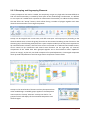
2.2.13 Grouping and Ungrouping Elements
If many components are used in a model, the complexity can get very high and it becomes difficult to
find out what functionality is created by which parts of the model design. Furthermore, it is difficult
to re-use parts of a model which represent an autonomous functionality. To address these problems,
the ACS offers the “Group” feature, which allows fusing a number of plugins together with their
channel interconnections into a single component.
Groups can be assigned with a new name, and offer new input- and output ports (according to the
channels which enter or leave the group) that also can be renamed according to their function in the
element group. The following example shows a quite complex model (on the left) which represents a
lip-controlled mouse solution, where 4 force sensors connected to an Arduino board enable mousecursor control via lip movements and several extra functions. On the right side, all “internal”
components of this model have been grouped together into a fused element called “LipMouse”
(shown in orange), so that only one slider component for speed adjustment, a buttongrid component
which provides On/Off buttons and the target mouse component remain visible:
Groups can be saved under a filename and may be imported into
other model designs. Available groups appear in the Component
menu under the “Group” selection. A Group can also be “ungrouped” which will display all the contained components and
channels again.
AsTeRICS User Manual
Page 24
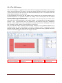
2.2.14 The GUI Designer
The ACS GUI Designer is a graphical editor which allows arranging the GUI Elements of the current
model. These GUI Elements are shown in the ARE GUI Designer window and can be freely positioned
/ resized. All GUI elements will be drawn and deleted automatically as soon as a component with GUI
will be added or deleted in the ACS model.
In the GUI Designer, the size of the ARE window and it’s position on the computer desktop can be
specified. Moreover, it is possible to define the visibility of the control panel and the window
decorations for this particular ARE model.
3rd-party windows (e.g. the OSKA window or the window of a live camera picture) are visible in blue
color and can be freely positioned on the whole desktop – not depending on the ARE window’s
position or size. A grid function eases the alignment of GUI Elements (using the “EnableGrid”
function, so that elements will snap to the grid). To visualize the grid, select “ShowGrid”. There are
four “GridSteps” (small, medium, large and huge) to choose from.
Thus, The ARE GUI editor provides complete design freedom for the graphical interface of an
AsTeRICS model and how it will appear on the user’s computer screen – ranging from a small
selection window without any decorations to a fullscreen interface with many graphical interaction
elements. The following figure shows the GUI Designer window:
The white panel symbols
the whole screen/desktop.
AsTeRICS User Manual
The red panel symbols the
GUI elements.
The light grey panel
symbols the ARE window
The grey panel symbols
the control panel
Page 25
2.2.15 Status Reporting and Error Logging
Within the tab “Miscellaneous (Misc.)”, status information and error logging can be requested from
the ARE (if an active connection to the ARE is available):
•
•
•
“Get ARE Status” opens a window, showing status messages from the components within the
ARE. These messages can be copied to the clipboard or saved to a file.
“Show Logfile from ARE” shows the ARE-logging file, containing status and error messages.
Beside this general information, the status of each component can be requested using the
Show Component Status in the context menu of each component.
2.2.16 Component Collection Manager
An AsTeRICS installation includes a component library ready to use in ACS. New plugins can be
imported to an existing library from a connected ARE and the new component library can be saved.
The Component Collection Manager is a small tool in which component collections (the description
of the available plugins within the AsTeRICS Runtime Environment) can be saved and administered.
Within the component collection manager, the following functionalities are provided:
•
•
•
•
Use Default sets the default ACS component collection as active component collection
Set as Autostart sets the active component collection as autostart component collection,
which will be loaded at ACS startup.
Save Component Collection saves the active component collection (e.g. a downloaded
component collection from the ARE) into the ACS folder.
The Saved Component Collections list shows all saved component collections. A component
collection can be selected and set active.
AsTeRICS User Manual
Page 26
2.2.17 Further ACS Options
Within the “Miscellaneous” tab, the “Options” dialog offers adjustment of General Settings, Dialogand Colour Settings:
General Settings:
•
•
•
•
•
•
“Reset Window Arrangement” resets all
layout settings to default values.
“Language” selects the ACS language
between English, German, Spanish and
Polish. The properties of the components
will not be affected by this.
“Connection Data” is responsible for the
connection of the ACS with the ARE. The IP
address of the ARE can be entered
manually or the ACS can try to detect the
ARE automatically in the local network.
“Connection Timeout” is the time period
the ACS waits for the ARE to respond to a
connection request for auto-detection.
“ARE Status Update” enables or disables an
automatic update of the ARE status. The
Update Frequency sets the time between
two status updates (in milliseconds).
If “Automatic backup files” is selected, the
ACS creates a backup file each time a
model is saved (the backup file gets the
extension “.acs.backup” and contains the
last version of the model).
Dialog Settings:
Within this options tab, dialogs can be activated or
deactivated. In the ACS, several dialogs have the
option Show this dialog every time. If a dialog has
been deactivated there, it can be reactivated in the
options dialog.
Colour Settings:
Within the Colours tab, the colours of the different
parts of a component can be changed. The colour
chooser not only allows changing the colour, but
also the transparency.
AsTeRICS User Manual
Page 27
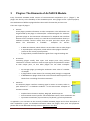
3
Plugins: The Elements of AsTeRICS Models
Every functional AsTeRICS model consists of interconnected components (a.k.a. “plugins”). The
plugins are the key to the flexibility of the AsTeRICS system. Every plugin serves a special purpose,
the combination of different plugins defines the model’s functionality and use-case.
There are 3 types of plugins:
Sensors:
These plugins provide information to other components. This information can
be generated by the plugin in software (like a simulated signal of a sinewavegenerator plugin or the interaction information of a Graphical User Interface
element on the computer screen) or it could be real measurements done by a
hardware modules. Sensors usually have no input ports but output ports
where the information is available.
Examples for sensors:
o A Slider GUI element, which delivers current slider value to other plugins.
o A JoystickCapture component, which informs other plugins of button
presses or the current joystick position.
o A plugin which provides bioelectric signals from a signal recoding unit.
Processors:
Processing plugins usually have input- and output ports. They perform
calculations or feature extraction tasks on input signals and provide the results
at their output ports, so that other plugins can use them. Examples:
o An Averager plugin, providing the arithmetic mean value of a number
of samples
o A plugin which creates events if an incoming word (strings) is recognized.
o A BlinkDetection plugin which finds out the moment when a person’s eye
blinks from a recording of muscle movements.
Actuators
The Actuator plugins transform incoming signal or events to actions, either in
pure software or – via hardware modules – in the environment. Examples of
actuators include:
o Graphical User elements: Displays, Bargraph, Oscilloscope etc.
o Environmental control systems: Infrared Remote Control, home automation etc.
o Input Device emulation: physical mouse / keyboard / joystick replacements
In Appendix A, an overview on the currently available AsTeRICS plugins and a short description of
their capabilities is given. For detailed information about the plugins, their ports and properties
please refer to the dedicated ACS-help sections (press F1 in the ACS).
AsTeRICS User Manual
Page 28
4
Step-by-Step Guide to AsTeRICS Model Creation
The following sections describe the basics of AsTeRICS model creation: How to connect the sensor-,
processor- and actuator plugins in the ACS to achieve the desired system behaviour.
The first model creation tutorial shows how to work with ports, events and properties. The resulting
model will not fulfil a useful assistive purpose, but it helps to understand the signal flow in an
AsTeRICS model and how to use plugins in the system design.
Then, a functional alternative mouse-cursor control model will be developed in several steps, which
allows using a computer mouse via head movements. The only hardware needed for this model is a
standard webcam (which is already included in most laptop / notebook computers).
The next model creation demo shows how to use standard computer input devices like gamepads or
the Wii Controller in AsTeRICS models.
Subsequently, more sophisticated system models are being developed and explained, supporting
different sensors and actuators. The interface to OSKA (the On-Screen Keyboard Application) will be
introduced, making it possible create on-screen keyboards for writing or graphical menus for
selection of commands or functions. This reveals the potential of the system for different use cases
like environmental control or mobile phone access.
4.1
Making a first Model: Using Ports, Events and Properties
For the creation of a very simple AsTeRICS model, we do not need external hardware components.
The only requirements are the ACS and the ARE software applications.
Every AsTeRICS model is constructed by adding and connecting system components (plugins) in the
ACS and adjusting the parameters of these components. The first model example will generate a
sine-wave signal and display the signal waveform in an oscilloscope window.
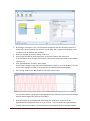
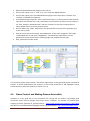
The “Signal Generator” demo:
Model file available: ACS\models\tutorial\1_SignalGenerator.acs
Start the ACS (by double clicking ACS.exe in the ACS folder)
Select “Components” in the main menu
Choose Sensors → Simulation → SignalGenerator
Choose Actuators → GraphicalUserInterface → Oscilloscope
Move the Oscilloscope icon to the right by dragging it with the mouse. Please note that all
design activities utilizing the mouse can also be accomplished be only using the keyboard
(see the ACS-help by pressing F1 in the ACS).
Connect the “out” port of the SignalGenerator to the “in” port of the Oscilloscope by
dragging the connection from “out” to “in”. This connection creates a data flow from the
SignalGenerator to the Oscilloscope component. The result comes into effect when the
model is started in the ARE. The result should look similar to the following screenshot:
AsTeRICS User Manual
Page 29
By clicking a component’s icon, the component properties and port descriptions become
visible in the Property-editor (can be seen on the right). Here, important settings for every
component can be defined and modified.
Now start the ARE (by double-clicking “ARE.exe”)
Connect ACS and ARE by choosing System → Connect to ARE in the main menu
If the connection does not work, please have a look at the connection setup as described in
section 2.2.5
Click “Upload Model” and then “Start model”
If notification dialogs during connection establishment come up, you can decide if you want
to see these dialogs next time or the connection and upload is performed silently
The running model in the ARE window should look similar to this:
The sine wave which is generated in the SignalGenerator element is sent to the Oscilloscope
element which displays the signal as intended
Now switch back to the ACS window and change the “frequency” property of the
SignalGenerator component from “2” Hz to “0.2” Hz – You can do this during the model is
running. After pressing Enter, the result becomes immediately visible in the ARE window:
AsTeRICS User Manual
Page 30
In the same manner, other parameters can be changed, for example the colours of the
Oscilloscope – just try it, and have a look at the purpose of each component-property in the
ACS help !
Certain modifications of the model (like port connections or addition of new elements)
cannot be done in a running model. For these operations, the model must be stopped.
Press “Stop Model” in the ACS menu and add a “Threshold” component from the submenu
Components → Processors → BasicMath
Connect the output of the SignalGenerator to the input of the Threshold component
Add an EventVisualizer from Components → Actuators → GraphicalUserInterface
Create an event channel by connecting the event trigger port of the Threshold component
(purple) to the event listener port of the EventVisualizer (green)
Click the event channel and select “eventPosEdge” and “eventNegEdge” from the pull-down
menu of “Threshold.1” in the property editor, which should look like:
Events represent sporadic information like pressing/releasing a button or a signal reaching a
certain level. In contrast to the input ports for signals (where only one connection is accepted
by an input port), several event channels can be connected to an event listener port. In the
AsTeRICS User Manual
Page 31
above example, event triggers will be generated by the Threshold component every time the
signal value passes the levels given in the component’s properties.
Now activate the “GUI Designer” view in the ACS window. Here you can specify the desired
area for the graphical output of every particular GUI component which is part of the model
Drag the GUI area of the EventVisualizer below the area of the Oscilloscope, so that these
two components do not overlap their graphical output. Adjust the size and position of the
components as desired:
Switch back to the Deployment window and change the gridColor or backgroundColor
properties as you like.
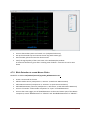
Upload and Start the model and have a look at the ARE window:
The EventVisualizer shows an Event from the Threshold component every time the signal
passed the set threshold level from below to above. Try to switch back to the ACS window
and modify the “eventCondition” parameter of the Threshold component to “both”. This
should lead to events being generated also when the signal passes from above to below.
AsTeRICS User Manual
Page 32
Finally, try to save the model (System → Save Model as), create a new model, load the model
again, store it on the ARE (System → Store Model on ARE; this saves a copy of the model
locally in the ARE) or set the model autostart when the ARE starts (System → Set as
Autorun).
This example has already introduced the most important tasks to create AsTeRICS models:
4.2
Adding components to a deployment model
Connection input and output ports for streaming data
Uploading and starting models in the ARE
Adjusting component properties
Using the GUI designer window to define GUI areas of components
Connecting Event channels and selection event triggers
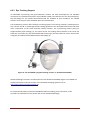
A Model for Mouse-Control by Head Movements
The models described in the following section provide headtracking-controlled mouse alternatives
for computer-input.
Model Description
The x- and y- position of the local
mouse are controlled by the user’s
head movement.
Requirements
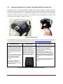
Remarks & considerations
A webcam (built in or
connected to an USB port of
the computer):
The first model example creates a
basic mouse replacement solution.
Mouse clicks are not supported and
have to be added via an external
Software tool (e.g. Point’n’click)
The “FacetrackerLK” sensor plugin is
used to perform the head tracking. This
plugin utilizes the Lukas Kanade optical
flow algorithm to track the face
features. This method is fast but not
100% stable (drifting of the tracking
point can occur).
The “FacetrackerCLM” component is a
possible alternative, it uses a different
algorithm which is slower but delivers
more features as eyebrow and eye lid
states.
In the subsequent examples,
clicking alternatives and adjustable
acceleration will be added to this
model.
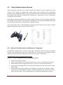
A high quality webcam is
recommended, e.g. Logitech
Webcam Pro 9000 shown
above.
For an optimal result, it is important
to place the camera directly in front
of the user (on top of the monitor of
the target computer, in a distance
about 70cm-120cm). No other
person’s face should be in the fieldof-view of the camera.
Table 1: Description of the camera mouse model
Creating a basic “head-controlled-mouse” model:
Model file available: ACS\models\tutorial\2_CameraMouse_basic.acs
Create a new model in the ACS (System → New Model)
AsTeRICS User Manual
Page 33
Insert the FacetrackerLK sensor component (Components → Sensors → ComputerVision)
This component captures life-images from a connected webcam and tracks the position of a
user’s face. The relative movement of nose and chin from last previous image frame to the
current image frame are available at the component’s output ports in x and y values. We will
use these for the mouse cursor positioning.
Insert the “Mouse” actuator (Components → Actuators → Input Device Emulation) and
connect to ports “noseX” to “mouseX” and “noseY” to “mouseY”
In the properties of the Mouse component,
o adjust xMax and yMax to the desired values (enter 0 for xMax and yMax to enable
automatic detection of the screen resolution if desired)
o deselect “absolutePosition”. This defines that the X and Y input values are relative
changes (for example -2/3) – which fits the output of the FacetrackerLK component.
o Note that “enableMouse” could be deactivated if it is desired to test the model
without real cursor movement.
o Select the “Synchronize Inputs” option in the InputPorts rider for both input ports
(mouseX and mouseY). This will wait for both input coordinates (x and y) to arrive
before the mouse position is updated.
Upload the model to the ARE. Before starting the model, be aware that you will lose control
of your mouse cursor is something is not working properly. You can stop the model by
activating the ACS window (Alt+TAB) and using the ACS hotkey (F7). You can still use the
normal mouse buttons for clicking.
Save the model under a suitable name
If the connection to the webcamera cannot be opened, the FacetrackerLK component will be colored
in red – indicating a problem in this component. In this case check the operation / driver of your cam.
AsTeRICS User Manual
Page 34
4.2.1 Extending the Head-Mouse: Add Dwell Clicking
The following example builds upon the simple camera-mouse model of the previous chapter. To
make this model really useable, several features will be added. To support left mouse clicks, several
options are possible, for example using an external switch which is connected via a DigitalIn
hardware module or via the Arduino microcontroller. Presses of a connected switch will create event
triggers which can be connected to the event listener ports of the Mouse component (e.g. Leftclick or
Rightclick) to perform the desired actions.
To avoid dependencies on any hardware – we will build a “dwell-clicking” function into the cameramouse model. “Dwell clicking” automatically performs a mouse button click when the mouse is not
moved for a longer time.
Camera Mouse with automatic dwell-clicking
Model file available: ACS\models\tutorial\3_CameraMouse_dwell.acs
Load the basic “2_CameraMouse_basic” model or build it as described above.
Add the processing component “Processors → Signal Shaping→ Deadzone” and connect the
noseX/noseY outputs of the FacetrackerLK component to the inX/inY input ports of the
Deadzone component. The Deadzone component can fade out x/y signal values in an
adjustable range and it can generate event triggers if the x/y values are inside or outside this
range. We will use this component to define a desired movement level to start or stop the
timing for the dwell click. The parameter “radius” defines this range – in our case the amount
of nose movement. We can leave it at the default value 10. Thus, the movement range is set
to 10 pixels from previous to current nose position.
In the Input Port rider of the Deadzone plugin, select “Synchronize Inputs” for inX and inY.
Insert a time sensor component “Sensors → Simulation → Timer”.
This component can measure time, generate events if a time period has passed, and perform
timing-loops. We will use it to define the time period of low movement which will generate a
dwell click. The default time-period of 2000 milliseconds could be adjusted to 1000 (which
gives 1 second dwell time) in the component parameters if desired.
Connect the event trigger port of the Deadzone component (purple) to the event listener
port of the Timer component (green) and click the event channel. Select the “enterZone”
event of the Deadzone component for the “start” function of the Timer component, and
select the “exitZone” event for the “stop” and “reset” functions:
AsTeRICS User Manual
Page 35
These event connections control the Timer component via the defined movement levels: if
the nose movement stays below the selected level 10 pixels, the Timer is started; else, the
Timer is reset to 0 and stopped. If the movement stays low for the full time period, the Timer
will generate it’s “periodFinished” event.
Draw a channel from the Timer’s event trigger port to the event listener port of the Mouse.
Assign the “periodFinished” event to the “leftClick” function:
This completes the dwell-click generation for our camera-mouse model.
Upload, start, test and save the model !.
AsTeRICS User Manual
Page 36
Try to change the dwell-radius (range) and the dwell-time to adapt the model to your own needs and
preferences. Like in every other model creation, it helps very much to display intermediate signals
and events in the ARE, using the GUI-actuators (Oscilloscope, BarDisplay, EventVisualizer, …).
Experiment by connecting these components to your signals and events!
4.2.2 Extending the Head-Mouse: Adjustable Parameters via GUI elements
Although extended camera-mouse model is already useable and provides left-click functionality,
there could be a lot of additional improvements. For example, it would be desirable to adjust the
mouse acceleration and the dwell timing to the user’s needs. Furthermore, different click-actions like
right- or drag-clicks should be supported. Adding GUI-support to your model which will provide these
extensions.
Camera Mouse model with GUI support
Model file available: ACS\models\tutorial\4_CameraMouse_GUI.acs
Load the “3_CameraMouse_dwell.acs” model or build it as described above
Add a Slider component (Components → Sensors → Graphical User Interface)
which will be used to make the mouse speed adjustable. In the Slider’s Properties, the range
of value can be defined. We can leave this at (0-100) but have to be aware of this range.
Set the Slider’s caption to “Mouse Speed” – indicating it’s desired function in the ARE GUI
Set the Slider’s minorTickSpacing to “10” – this defines that the slider will snap to steps of 10
values which makes it easier to use it with single clicks.
To modify the x/y mouse speed, we use a MathEvaluator processing component
(Components → Processors → BasicMath). We will need one for the X-signal and one for the
Y-signal. Let us first modify the X-direction:
Delete the port connection from noseX to mouseX.
Draw a new port connection from the “value” (Slider component) to “inA” (MathEvaluator)
Draw a new connection from noseX (FacetrackerLK) to “inB” (MathEvaluator).
Adjust the “expression” property of the MathEvaluator as desired. The “expression” property
defines how the values of the input ports will be combined to generate the output value of
the MathEvaluator component. For our example it seems reasonable to multiply the nose
movement value (inB) with the current Slider value (inA). Furthermore, we should divide the
Slider value (which can range from 1 – 100 as defined in the Slider’s properties) by 50. This
means that Slider positions < 50 will slow down the mouse speed, while values >50 will
increase the mouse speed up to the double of the original value.
So for the “expression” property we enter “a/50*b”.
Do not select the “Synchronize Input” option in the Input ports rider of the MathEvalutator
component. This would wait for new value to arrive at “inA” and “inB” before a calculation,
but in this case inA comes from the slider and is only updated when the silder is moved via
the GUI.
Connect the output port of the MathEvaluator to the “mouseX” input port of the Mouse.
Now the model looks like it can be seen in following figure.´:
AsTeRICS User Manual
Page 37
Copy and Paste the MathEvaluator to create a second one for the Y – direction. Connect the
second MathEvaluator to the slider and to the noseY-output of the Facetracker plugin - as we
did it for the X-direction. Upload and test the model.
An additional useful feature would be to enable different mouse click activities. This could be done
easily by attaching a switch for right clicks via the DigitalIn hardware module (see section 6), but we
can also provide flexible clicking actions via the GUI.
For this purpose, we will add a ButtonGrid to select the next click type and inform the mouse
element about the next desired click type by sending a proper “action string” to the Mouse element.
Action strings contain commands which are understood by a number of specialized actuator
elements (Mouse, Konnex, IRTrans ,…). These strings contain the addressed component and the
desired command (e.g. “@MOUSE:nextclick,right”).
For details please refer to the help files of the respective components, or Appendix B .
To Enable different click-types:
Add a ButtonGrid component (Sensors → Graphical User Interface → ButtonGrid)
Set the “buttonCaption” properties of button 1, 2 and 3 to
“RightClick”, “DoubleClick” and “DragClick”
Choose “horizontalOrientation” for the ButtonGrid and set a desired caption:
AsTeRICS User Manual
Page 38
Define a desired position for the ButtonGrid component in the “GUI Designer” view.
Now add the a StringDispatcher component (Processors → Event and String Processing)
This component can be used to translate incoming events into outgoing strings. We will use it
to generate desired action strings for the Mouse component if buttons are pressed on the
GUI.
Connect the event trigger port of the ButtonGrid component to the event listener port of the
StringDispatcher
Click the event channel and attach “button1” to “dispatchSlot1”, “button2” to
“dispatchSlot2” and “button3” to “dispatchSlot3”
Now define the strings for slot1 – slot3 in the properties of the StringDispatcher:
slot1 (button1): “@MOUSE:nextclick,right”,
slot2 (button2): “@MOUSE:nextclick,double”,
slot3 (button3): “@MOUSE:nextclick,drag”
Connect the output port of the StringDispatcher to the “action” input port of the Mouse.
AsTeRICS User Manual
Page 39
This resulting model provides a fully functional mouse replacement with left / right / double and drag
click support using a webcamera for head tracking and a GUI for mouse click selection and mouse
acceleration adjustment. Save the model as “camera_mouse_dwellclick_GUI.acs”, upload it to the
ARE and start it. Depending on how you arranged the GUI elements in the designer window, the ARE
window could look as follows:
Of course, several other features could be added to improve the model. For example, the
facetracking could be re-initialised if the face position got lost (via an event trigger of the
FacetrackerLK component and a button or external switch). Or different modes or presets could be
provided, like a Joystick-mode for the mouse, where head movement translates into the speed of the
mouse cursor, not into the absolute position. Such extensions are provided in the AsTeRICS model
collection.
AsTeRICS User Manual
Page 40
4.3
Using Standard Input Devices
Off-the-shelf game controllers for personal computers are available in every hardware store, they
provide a lot of buttons for digital input, several analog inputs (commonly two 2-dimensional
joysticks) and are affordable. With the success of gesture input and movement based controllers (like
the Nintendo Wii), additional modalities like acceleration or angle velocity can be measured by
several game control devices.
Depending on the physical capabilities of a person, game controllers can be interesting input devices.
The AsTeRICS system allows using standard PC gaming pads or the Nintendo WiiMote (optionally
with the Nunchuk extension) as input devices for AsTeRICS models.
The pictures below show a HID-compatible PC gamepad (price about 10 Euros) and the wireless
Wiimote with Nunchuk-extension (price about 35 Euros).
4.3.1 Mouse-Click Alternatives via Buttons of a Gamepad
The following example shows a model to create right- and double mouse clicks with two desired
buttons of a PC gamepad / joystick. This could be useful for a person who uses a sufficient mousereplacement solution but has problems with the efficiency of right- or double clicks.
Emulate Mouse clicks via Gamepad/Joystick buttons
Model file available: ACS\models\tutorial\5_Gamepad_Click.acs
Create a new model in the ACS
Add the JoystickCapture sensor plugin (Components → Sensors → Standard Input Devices)
Add the Mouse actuator plugin (Components → Actuators → Input Device Emulation)
Connect the event trigger port of the JoystickCapture plugin to the event listener port of the
Mouse plugin
Click the event channel and assign the “pressedButton1” trigger to the “rightClick” listener,
then assign the “pressedButton2” trigger to the “doubleClick” listener. Of course, also other
buttons could be used – choose the best buttons for the physical capabilities of the user
AsTeRICS User Manual
Page 41
Start the ARE (if not already running) and connect the PC gamepad to a USB port
Press “Connect”, “Upload” and “Start Model” to run the model and test its functionality
4.3.2 Joystick-based Mouse replacement
Using the input capabilities of a gamepad or joystick, many different use-cases could be created with
the AsTeRICS system. The next example will extend the mouse-click alternative to a fully functional
mouse replacement via one joystick and desired buttons of a gamepad.
Complete Mouse Emulation via Gamepad/Joystick
Model file available: ACS\models\tutorial\6_Gamepad_MouseEmulation
Load the “5_Gamepad_Click.acs” model or create it as shown in the previous example
Add two Oscilloscope plugins (Components → Actuators → Graphical User Interface) and
connect the output ports “x” and “y” of the JoystickCapture plugin to Oscilloscope1 and
Oscilloscope2. This will show the x and y values of the left joystick.
Arrange the areas of the oscilloscopes in the GUI Designer window so that both are visible.
Upload and start the model to view the incoming values in the oscilloscope displays when
you are moving the joystick. The values should range from 0 to 255.
Stop the model, select the JoystickCapture component in the ACS and modify the
“updatePeriod” property from 100 to 20 milliseconds. This will increase the speed of joystick
measurements to 50 values per second. Verify this by uploading and starting the model.
Stop the model again, and add a “MathEvaluator” component. This component can be used
to calculate mathematical expressions containing up to 4 input signals.
Select the MathEvaluator and enter “(a-127)/10” in the property “expression”. This will
subtract 127 from the joystick value and then divide by 10, which will modify the range of
values from 0-255 to about -12.7 to 12.8; When the joystick is not touched, the value will be
zero. This can be used to create a mouse speed out of the joystick value.
AsTeRICS User Manual
Page 42
Duplicate the MathEvaluator plugin (Ctrl+C, Ctrl+V)
Connect the output ports “x” and “y” to “inA” of the two MathEvaluators
Connect the output ports of the MathEvaluator plugins to the input ports “mouseX” and
“mouseY” of the Mouse component
In the Mouse plugin properties, select “Synchronize Inputs” (in the Input Ports rider)for both
input ports, this will wait for x and y coordinate to arrive before the mouse cursor position is
set. Then, deselect “absolutePostion” which is necessary to treat the incoming values a
mouse speed and not as mouse position values.
Set the “xMax” and “yMax” properties to the desired area for mouse move (probably your
screen size in pixels)
Click the event channel and assign “pressedButton3” to the event “dragPress” and assign
“releasedButton3” to the event “dragRelease”. This effectively maps button 3 of the
gamepad to the left mouse button, allowing single click, double click and drag.
Save, upload and test the model.
This relatively simple model creates a full mouse replacement via the gamepad joystick and desired
buttons. A useful recapitulation and extension of this model would be to add adjustable mouse
acceleration by a slider GUI element (as shown in 4.2.2).
4.4
Game Control and Making Games Accessible
Gameplay is a very good way to raise motivation for training and can result in surprisingly good
interaction results also for people with severe motor conditions. An example of creative input
mapping is the PC gameplay of “gaming kitsune” - http://www.youtube.com/watch?v=-y0-0f_bZ6w
See also the “Custom Button Remapping Initiative” by Chuck Bittner: http://www.askacapper.com/
AsTeRICS User Manual
Page 43
4.4.1 PC Input Emulation for Games using Keyboard
Many games (especially new PC-games) need certain keyboard- or game controller interactions
which cannot be considered as “accessible”. Here, we can try to create AsTeRICS models which
generate the needed keyboard actions (e.g. key press, -hold, -release) or mouse inputs by desired
sensors, or a model which remaps the game controller buttons according to the needs of a user.
In the next example the buttons of a standard PC gamepad are used to create keyboard input on the
local keyboard. 4 buttons will be used to generate cursor keys (up, down , left, right) another button
will be used to generate the “Enter” key. This model will be evaluated by a game of BubbleBobble on
the free C64 emulator software.
Generate Keystrokes for the Cursors Keys
Model file available: ACS\models\tutorial\7_CursorKey_Emulation.acs
Create a new model in the ACS
Add the “JoystickCapture” plugin (Components → Sensors → Standard Input Devices)
Add five “Keyboard” plugins (Components → Actuators → Input Device Emulation)
In the property “keyCodeString” of Keyboard 1,2,3,4 and 5 enter the desired Key-Codes, for
example: “{UP}”, “{DOWN}”, “{LEFT}”, “{RIGHT}” and “{ENTER}”.
Please note that the “keyCodeString” could also contain letters and other special keys, for
example “Hello {CTRL}a” or “{ALT}{TAB}” etc. A full list of supported Keys is supplied in
Appendix C…
Now connect the event trigger port of JoystickCapture to the event listener ports of all five
Keyboard components.
For every event channel: Assign the “pressedButton” event of the desired button to the
“holdKey” event of the Keyboard plugin, then assign the “releasedButton” event to the
“releaseKey” event. In the figure below, Button 7 of the gamepad is assigned to “hold” and
“release” of one Keyboard plugin.
This mapping will generate and hold a key press when the gamepad button is pressed.
The key is released when the button is released.
If you are unsure which button number your desired button has, you could use an
EventVisualizer plugin to view the events which are generated as you press the buttons.
Alternatively, you can test the button numbers in the property window of the game
controller in the windows device manager.
AsTeRICS User Manual
Page 44
The resulting model and the game window (here the classic “BubbleBobble”, played on the free
CCS64 emulator via the AsTeRICS model) can be seen in the following pictures:
Figure 1: Joystick-based key emulation model, and a game of “BubbleBobble”:
4.4.2 PlayStation 3 Control and HID Device Emulation
The Sony PlayStation 3 (PS3, see http://uk.playstation.com/ps3/) can be controlled by the AsTeRICS
platform via a special piece of hardware – the so-called “HID-Actuator”. The HID-Actuator allows
emulation of a standard Human Interface Devices (HIDs) like for example the PS3 USB game
controller, to give people with disabilities options to control this gaming console via desired sensors.
The HID actuator looks like a USB stick but behaves like a mouse, keyboard or joystick when plugged
into a target computer. A wireless HID actuator is commercially available from AsTeRICS partner IMA
(see chapter 6), a Do-It-Yourself building guide for electronics-hobbyists is available in the DIY-section
of the AsTeRICS homepage (please refer to http://www.asterics.eu/index.php?id=73).
AsTeRICS User Manual
Page 45
4.5
Environmental Control with OSKA and Infrared Remotes
In the following model example, a universal infrared remote control is utilized to control a music
center/CD-player. The user can select desired functions of the music center by choosing graphical
symbols in an on-screen keyboard. There are some hardware and software requirements for this
model, which are described in the table below:
Model Description
This model enables Infrared
remote control of a music player.
The IR-commands are learned
from the original remote-control
using the IR Trans GUIClient
software tool.
These infrared commands are
triggered via an on-screen
keyboard grid which sends a
number of pre-defined command
names when the according cells
have been selected.
Requirements
Remarks & considerations
For the Infrared code learning
and playback, the IrTrans device
has to be available and installed.
See http://www.irtrans.de
This model provides mouse or touch
screen interaction. Scanning or
webcamera / headtracking-based
selection of keys/symbols could be
added if desired.
Some standard on-screen
keyboard grids which are
delivered with the AsTeRICS
package can be used for free.
For creating custom grids, the
OSKA editor must be purchased
from
http://www.clarosoftware.com/in
dex.php?cPath=365
The infrared remote control
commands of the desired music
player or home entertainment device
can be learned as described in the
IRTrans manual.
Table 2: A model for On-Screen Keyboard controlled Infrared Remotes
The IRTrans universal infrared controller can learn and replay arbitrary IR commands. It connects to a
PC or to the AsTeRICS Personal Platform via USB, LAN or WLan (depending on the model). Using the
IRTrans “GUIClient” tool, IR-commands of a desired remote control can be recorded and stored
under a desired command name. The following figures show the IRTans module (LAN version) and
the GUIClient software tool:
To learn new IR-codes, the following steps are performed in the IRTrans “GUI client” tool:
A Command is recorded from an individual IR remote control
Remote control- and command name are be assigned, multiple remotes are possible
Commands are stored in a database and can be flashed into the IRTrans device
AsTeRICS User Manual
Page 46
To replay recorded commands within the AsTeRICS system, the IRTrans actuator plugin accepts
command names which have been learned with the IRTrans GUI client at its “action” input port.
For a convenient selection of the desired infrared remote command, OSKA (the On-Screen Keyboard
Application) is used. The free OSKA player is part of the AsTeRICS framework. (For a detailed
description of the OSKA features please have a look at chapter 5).
In the AsTeRICS model, the OSKA plugin is configured to display an on-screen keyboard grid named
“aat_hifi.xml” which is available in the subfolder “OSKA/keyboards/homeControl”. The grid has
several keys (cells) which correspond to the function of the music player:
When the user selects a cell, OSKA sends suitable action strings to the OSKA plugin. These actions
strings can be defined in the OSKA editor and comply to the following format:
“@IRTRANS: snd <remotename>,<commandname>”, where <remotename> and <commandname>
correspond to the learned infrared commands. When a cell has been selected, the action string is
emitted by the “action” output port of the OSKA plugin. This port is connected to the “action” input
port of the IRTrans plugin, so that the action strings are transferred to the IRTrans module, which
sends the associated infrared code.
The “aat_hifi” keyboard grid is pre-configured to send the following action strings:
Key caption
On/OFF
select MP3/CD/Radio/External
increase volume
reduce Volume
Previous
Next
Pause
Play
Stop
Back to main Menu
AsTeRICS User Manual
Function
Switch to/from standby
Change mode of operation
Change Volume
Change Volume
Change track
Change track
Play/pause
Play/pause
Stop
Change the grid
Action string
<@IRTRANS:snd asterics,rc_operate>
<@IRTRANS:snd asterics,rc_function>
<@IRTRANS:snd asterics,rc_volume_up>
<@IRTRANS:snd asterics,rc_volume_down>
<@IRTRANS:snd asterics,rc_previous>
<@IRTRANS:snd asterics,rc_next>
<@IRTRANS:snd asterics,rc_play>
<@IRTRANS:snd asterics,rc_play>
<@IRTRANS:snd asterics,rc_stop>
<ChooseGrid:aat_homecontrol>
Page 47
Thus, the “aat_hifi.xml” keyboard grid can be used without any change if a remote control named
“asterics” and the command names given in the above table have been learned and stored into the
IRTrans device using the “GUI client” software tool.
Alternatively, the action strings can be modified to different remote control- and command-names as
shown in 5.2.2
Using the OSKA On-Screen Keyboard and the IRTrans for Infrared control
Model file available: ACS\models\tutorial\8_OSKA_InfraredRemote.acs:
Create a new model in the ACS and add the “OSKAExternalScanning2d” plugin
(Components → Processors → OSKA)
Enter the grid name “keyboards\homeControl\aat_hifi.xml” into the property
“keyboardPath”. If the ARE is connected and the model is uploaded (synchronized) you can
choose the keyboard name from a pull-down list of available keyboards
Add the IrTrans Plugin (Components → Actuators → Home Control)
Connect the “action” output port of the OSKA plugin to the “action” input port of IrTrans
If you have the USB version of IrTrans, enter “localhost” into the “hostname” property of the
IrTrans component and start the IRTrans server tray; If you have the Lan- or WiFi version,
enter the IP-address of the IrTrans module.
Figure 2: OSKA Keyboard layout and ACS model design for the IR-control application
If alternative sensor input is desired to switch and select keys, the event inputs of the OSKA plugin
can be used.
AsTeRICS User Manual
Page 48
4.6
Mobile Phone Control
Currently, AsTeRICS is able to interface with mobile phones running
Windows Mobile (5.0 and above), Android Phones (2.1 and above)
and GSM modems. Dedicated AsTeRICS plugins allow making phone
calls, accepting and disconnecting phone calls and sending and
receiving SMS.
The connection between AsTeRICS and the phone is established using
Bluetooth or WiFi and a special server application which is installed
on the phone (part of the AsTeRICS package). The figure on the right
side shows a mobile phone with the AsTeRICS phone server
application running.
4.6.1 Controlling a Windows Mobile 6.5 phone
For connecting a Windows Mobile Phone to the ARE, a Bluetooth device must be available and the
Phone Library Server Application has to be installed on the phone (ServerInstall.cab file provided in
the AsTeRICS release package), as outlined in the following steps:
If you are using Windows XP install the ActiveSync application.
Connect the phone to PC using a USB cable. On Windows 7, if you connect the Windows
Mobile phone for the first time, the Microsoft Windows Mobile Device Center application
will be installed automatically.
Using ActiveSync or Windows Mobile Device Center, copy the Server installer to the phone
and run it.
After Installation of the Server Application, switch on Bluetooth on your phone and make it visible,
then run the Server Application. After that, the PhoneControl plugin (Actuators → PhoneInterface →
PhoneControl) can be used to connect the phone and control the SMS and Call functions:
Enter the phone's Bluetooth name, which can be read from the Bluetooth settings of the
phone, into the “bluetoothPhoneName” property.
Enter the phone number you want to call into the “defaultPhoneID” property, using
+<country code><phone number> notation.
Connect the Event Listener ports of the PhoneControl plugin to desired event triggers which
should activate the respective functions. Please refer to the ACS help for the PhoneControl
plugin for details.
A nice GUI is helpful for using the phone functions. The next example shows how to use the
OSKA On-Screen Keyboard for that purpose.
AsTeRICS User Manual
Page 49
4.6.2 Controlling an Android Phone
Mobile phones running Android 2.1 and above can be integrated with the ARE. For this, the
AsTeRICSPhoneServer application must run on the phone, which communicates with the
AndroidPhoneControl plugin. The connection between the phone and the plugin is done via the TCP
protocol. In most cases the connection is established through WIFI technology.
The AsTeRICSPhoneServer application is part of the AsTeRICS runtime distribution and can be found
in the folder /Android. Install the AsTeRICSPhoneServer.apk file by copying it to the Android phone
(via USB, email, etc.) and running it on the phone, e.g. by using a file system browser app.
The figures below show the running PhoneServer on the Android phone (left) and the properties of
the ARE AndroidPhoneServer plugin (right).
If the AndroidPhoneServer plugin is configured to act as “server”, the AsTeRICSPhoneServer app
running on the Android device must be configured to act as “client” and vice versa. If the connection
is done via public network, the device with the public IP should act as server. If both devices are on
the same local network, it does not matter which device acts as the server.
For the device which acts as client, the server IP address must be provided (ARE plugin: in the IP
property , AsTeRICSPhoneServer App : in the Server IP property). Then, set the same port number for
both devices (default port number is 21111).
Choose “EnableServer” in the App and run the ARE model. Wait for a connection between ARE and
Phone.
Features of the AndroidPhoneServer plugin:
The phone number of the remote receiver can be set using the defaultPhoneID property or via the
PhoneID input port. The SMS message text can be set using the SMSContent input port. If the phone
is connected, it can be controlled by several event listener ports which accept incoming events.
A demo model file is available here: ACS\models\tutorial\9_AndroidPhone_Control.acs
AsTeRICS User Manual
Page 50
Phone function control via Event Listener ports of the AndroidPhoneServer plugin:
•
•
•
•
MakePhoneCall – Makes a call to the remote receiver.
AcceptPhoneCall – Accepts incoming phone calls. Remark: The accept call function may not
work for Androd 4.1 (Jelly Bean) phones, if the wired headset is not used.
DropPhoneCall – Drops incoming phone calls or finishes phone calls.
Send SMS – Sends the SMS.
The phone state is provided by the Event Trigger ports of the plugin:
•
•
•
•
•
idleState – The phone is in the idle state.
ringState – The phone is calling. Caller number is given by the RemotePhoneID output port.
connectedState – The phone is connected.
newSMS – There is a new SMS. The message is given by the ReceivedSMS output port
Error – An error occurred. The error number is given by the ErrorNumber output port.
The phone can be also controlled by text commands (actions strings) sent to the “action” input port:
•
•
•
•
•
•
•
•
@PHONE: CALL: Phone_ID – Calls to the Phone_ID number
@PHONE: CALL – Makes a call to the phone number which was set earlier.
@PHONE: ACCEPT – Accepts incoming phone calls
@PHONE: DROP – Drops incoming phone calls or ends calls.
@PHONE: SET_ID: Phone_ID – Sets the phone number.
@PHONE: SET_SMS: "Message_content" – Sets the SMS message.
@PHONE: SMS:Phone_ID, "Message_content" – Sends Message_Content to the Phone_ID
@PHONE: SMS – Sends the SMS message.
This allows an easy combination with OSKA grids that send the appropriate action strings to the
plugin when a cell in the OSKA grid is selected. The screenshot below shows the example grid
OSKA\keyboards\phoneControl\phone_android_menu.xml:
For functional operation it is sufficient to select this grid in the OSKA plugin and connect the “action”
output port of the OSKA plugin to the AndroidPhoneServer plugin’s “action” input port.
AsTeRICS User Manual
Page 51
4.7
Working with Bioelectric Signals: the Enobio BNCI Recording Unit
The Enobio Device is a wireless Biosignal acquisition unit for Brain and Neural Computer Interfaces
developed by the AsTeRICS partner company Starlab Living Science (Barcelona). Enobio provides 4
channels of bioelectrical signals - for example EEG, EMG EOG or ECG. The Enobio sensor component
interfaces the Enobio device to the ARE, so that signals recorded by Enobio are available to be
processed by other plugins running in the ARE.
Figure 3: Starlab Enobio
For a detailed explanation of the Enobio features, price information, software support and guidelines
how to charge or attach the device please have a look at: http://starlab.es/products/enobio
Model Description
Requirements
Remarks & considerations
The following model descriptions
provide an interface to the Enobio
unit for blink detection. The eyeblinks are used to create single or
double clicks of the left mouse
button.
An Enobio unit must be
available and installed on the
computer. The internal
battery is charged, and the
operation of the hardware
has been verified using the
Enobio software which is
delivered with the product.
There are various ways how Enobio
could be used in the AsTeRICS
framework, including EOG, EMG and
EEG applications.
The major Brain-Computer-Interface
(BCI) paradigms which allow computer
control by brainwaves, for example P300,
SSVEP and movement imagination can
be interfaced via the OpenVibe bridge
plugin.
Such models could be combined
with the camera-mouse model or
used together with OSKA to
perform eye-blink controlled
scanning.
Other possible applications are
the modification of modelparameters or model switching by
double-eye-blinks.
Additionally, dedicated AsTeRICS plugins
are available for SSVEP based BCI
setups.
Table 3: Description of the Enobio eye-blink detection
AsTeRICS User Manual
Page 52
4.7.1 Display Enobio Signals and Verify the Signal Quality
This basic model will display the Enobio signals to check electrode connections and verify the signal
quality. (As a requirement, the Enobio hardware has to be available and the drivers for the correct
system architecture need to be installed – please refer to the Enobio documentation.)
Create a new model in the ACS
Add the Enobio sensor (Components → Sensors → Bioelectric Measurement)
Add the EnobioDisplay actuator (Components → Actuators → Graphical User Interface)
Place the components next to each other and connect all channels:
AsTeRICS User Manual
Page 53
Connect the Enobio System and switch it on (red power led active)
Set up the electrode cap and connect the ear clip (with contact gel)
Start the ARE, upload and start the above model
Verify the signal quality of the traces seen in the EnobioDisplay window:
all channels should turn green after a settling time of about 1-2 minutes as can be seen
above
4.7.2 Blink Detection to create Mouse Clicks
Model file available: ACS\models\tutorial\A_Enobio_BlinkDetection.acs:
Create a new model in the ACS
Add the Enobio sensor (Components → Sensors → Bioelectric Measurement)
Add a Mouse actuator (Components → Actuators → Input Device Emulation)
Add a BlinkDetection processor (Components → Processors → DSP and Feature Detection)
Connect “Channel1” of the Enobio component to “input” of the BlinkDetector
Connect the event trigger port of the BlinkDetector to the event listener port of the Mouse
component, attach “BlinkDetected” to “leftClick” and “DoubleblinkDetected” to “dblClick”:
AsTeRICS User Manual
Page 54
The above model creates left and double clicks by eye blinking. Of course, this configuration could be
added to the camera_mouse model, replacing the automatic dwell-clicking if desired.
4.8
Other interesting models and system capabilities
The model creation examples in this chapter could only give a first impression what is possible with
the AsTeRICS plugins - just a small portion of the available plugins could be covered. Additional demo
models can be found in the ACS subfolder “ACS\models\useCaseDemos”):
Voice recognition and synthesis in various languages via the SpeechProcessor plugin
Home Automation and smart home control via the KNX and FS20 plugins
A DIY-gaze tracking solution featuring eye-tracking with head-pose correction - described in
the DIY-guides and supported by dedicated models
Several TCP-based bridges provide interfaces to other frameworks
including major BCI projects like OpenVibe (http://openvibe.inria.fr/)
or Tobi (http://www.tobi-project.org/)
The GestureFollower system for online gesture recognition can be integrated
(http://ftm.ircam.fr/index.php/Gesture_Follower)
The ARDrone quadcopter and the Ladybird quadcopter have been interfaced with AsTeRICS
using WiFi and PPM-based radio links
A pneumatic mouthstick gripper and a 4-Degrees-Of-Freedom mouth-joystick
A force-sensor based lip-mouse solution with sip/puff click selection
Please note that many of these models depend on additional hardware or software and will not work
“out-of-the-box” on a standard PC or Laptop. If you have questions or problems please contact the
AsTeRICS Team via the homepage or consult the user forum.
AsTeRICS User Manual
Page 55
OSKA – The On-Screen Keyboard Application
5
The OSKA Suite is a commercial Assistive Technology software collection by the company
ClaroSoftware (http://www.clarointerfaces.com)
OSKA Suite provides a configurable On-Screen Keyboard with various features like keyboard grid
editor, support of different input devices, scanning and word prediction. (Scanning is a special input
method where keys are automatically highlighted and can be selected by e.g. a single switch input.
Several scanning techniques exist, e.g. Row/Column scan, User-triggered scan etc.)
Furthermore, several assistive tools for alternative mouse input are part of the OSKA Suite, including
TenKey Mouse, OneSwitch Mouse, ScrollWheel Scanning and others. For detailed information please
visit:
http://www.clarointerfaces.com/products/oska-suite.php
The core product of OSKA Suite is an on-screen keyboard application, which can be interfaced to the
AsTeRICS system. The OSKA on-screen keyboard has 3 main components, delivered as stand-alone
software applications for Windows (compatible with Windows 7, Vista and XP):
OSKA Editor, to create Keyboard grids and define ARE action commands
OSKA Keyboard, the actual on-screen keyboard application
The OSKA Settings Editor, to select input method and options
For the AsTeRICS project, the OSKA Keyboard is provided as freeware, and it is included in the
“AsTeRICS-Runtime” download package. OSKA Keyboard serves as a primary Graphical User Interface
for various AsTeRICS use cases. Due to a dedicated OSKA plugin for the ARE it becomes possible to
influence selections in the on-screen keyboard grid with desired sensors, or to control desired
parameters or actuators in the AsTeRICS model via OSKA and a touchscreen.
5.1.1 OSKA Keyboard
OSKA provides a wealth of features specifically designed for users who cannot easily use common
input devices:
Text entry into all standard Windows applications, just like using a standard keyboard
Includes a range of keyboard templates including Mouth Stick and Head Pointer Keyboard
Offers a range of keyboards in different languages
Keyboard templates can be edited or designed from scratch for full customization
Support of existing pointing devices or switch systems
Supports Full Switch/Scanning Operation
Macros and User Definable Keys, Menu Shortcuts
Word Prediction
Fully supports touch technology such as touch screen laptops and PCs
Can be seamlessly integrated with AsTeRICS sensors and actuators
AsTeRICS User Manual
Page 56
The following screenshots show two examples of OSKA Keyboard grids which are used together with
the AsTeRICS framework for environmental control applications. The first screenshot shows an OSKAgrid to control a TV-set via infrared remote control (via the IRTrans infrared device):
The second screenshot shows control of rooms lights via the Konnex home automation network
(interfaces via the Konnex plugin and a KNX/IP router):
Of course, also “classical” on-screen keyboard layouts providing alphanumerical characters for
alternative keyboard input in software applications is possible. The keyboard grid layout and
functionality is defined using the OSKA Editor.
5.1.2 The OSKA Editor
The OSKA Editor allows keyboards to be adapted to specific requirements. All the keyboards in OSKA
are fully customisable, allowing the keyboard to be edited to suit the requirements of each user and
task. The features of the OSKA Editor allow to:
Define the Keyboard Layout: Select the number of buttons on the keyboard. The number of
columns and rows required and the size of the buttons in the Current Grid Setting can also be
specified; Enter the text to be displayed on the button
Modify Grid Settings: Enables the size, the number of columns and rows, and the gaps
between the buttons to be edited.
Adjust Button Settings: The style and appearance of individual buttons can be edited. This is
also where labels or descriptions of the button and background images can be added.
Change Colours and Appearance, select Background Images and Fonts
AsTeRICS User Manual
Page 57
Define Special Actions for Keys/Buttons:
o Play a sound or speak a text
o Start an Application
o Change the current keyboard grid
o Influence the scanning speed
o Control the mouse cursor position and clicking
o Control the on-screen keyboard position
The following screenshot shows the OSKA Editor in operation. The user interface is multi-lingual,
here the German version of the user interface is shown.
5.1.3 The OSKA Settings editor
After a keyboard is created in the OSKA Editor, the input methods
can be defined and customised. In addition, certain keys can be
further defined, giving further capability. The OSKA Settings Editor is
designed to allow the setup of the input methods of keyboards that
have been created in the OSKA Editor.
There are five input methods to choose from. Depending on the
individual capabilities of a user, these can be set to allow the best
control method of the keyboard.
AsTeRICS User Manual
Page 58
OSKA Input Methods:
Keyboard Input: offers the choice of using either the cursor keys and the enter button or the
numerical keypad and keypad enter button to move and select keys on the OSKA keyboard
Mouse Input:
o “Point and Click” - standard mouse movements control the mouse cursor. Clicking
the mouse button will perform a left click
o “Point and Hover” - standard mouse movements control cursor movement. After
hovering over an item for a predetermined amount of time the item is selected
(when cursor is stationary). The time it takes to automatically select an item can be
edited
Gamepad Input:
o “Map to Keyboard“ uses the analogue gamepad joystick to move the selector around
the keyboard. One of the gamepad buttons is then used to select the key
o “Map to grid” is designed to be used on square keyboard layouts with sides of 5, 8 or
9 buttons. This allows for selections based on two gamepad directional inputs
Scanning Input: Scanning input cycles through the keys using a switch/scanning method. The
scanning input can be controlled by clicking the mouse, pressing a joystick button or pressing
a key switch to select.
Mouse/Touchpad Grid Input
o “Mouse X & Y” - highlights an individual key. Very small movements on the touchpad
(or by a mouse) will cause the highlight to move in the direction of the keys
o “Mouse Wheel, Mouse X and Mouse Y” - works in a similar manner to two switch
scanning. Move the mouse wheel (or finger/mouse horizontally/vertically) and the
row/column will be scanned. Then click either the mouse wheel or one of the
'checked' mouse buttons. Individual keys will now be scanned by moving the mouse.
Click to select a key.
5.1.4 Using Word Prediction and the Communicator Line
OSKA offers some interesting features beyond the on-screen keyboard functions, for example word
prediction and a communicator line. The word prediction offers up to 5 suggestions which can be
placed on desired keys. Using the prediction editor, dictionaries can be created from word
documents, text files or separate words. Dictionaries for multiple languages are available. A
dictionary is selected using the settings editor, where also the “learn new words” functions can be
activated – so that the dictionary is extended during typing.
The Communicator line allows composition of a longer input sequence / sentence, which can then be
sent to the ARE (e.g. to send an SMS) or spoken by the speech synthesizer.
AsTeRICS User Manual
Page 59
5.2
Using OSKA Keyboard together with the ARE
OSKA Keyboard is part of the OSKA Suite by ClaroSoftware, it displays functional on-screen keyboards
which have been created using the OSKA Editor. Together with the OSKA plugins for the ARE, OSKA
Keyboard offers a powerful user interface front end for AsTeRICS. There are three OSKA plugins,
specialized for different scanning variants: internal scanning (automatically done in the OSKA
applications) and external scanning (via sensor information from the ARE)
These Plugins feature the following functions to interact with the OSKA Keyboard application:
The OSKA plugins can start the OSKA Keyboard application, to display the on-screen keyboard
when a system model is started.
The OSKA plugins can shut down the OSKA Keyboard application when a model is stopped.
OSKAExternalScanning1D and OSKAExternalScanning2D haves input ports to accept cell
coordinates and event ports for cell selection
The OSKAInternalScanning plugin starts OSKA in internal scanning mode and has event ports
for cell selection
Action Strings can be sent from OSKA Player to the ARE plugins to control actuators,
influence model parameters (for example sensitivity of a sensor) or switch to another model
The OSKA Player and the ARE plugins are connected via TCP/IP, which means that OSKA Keyboard
could run on a different computer than the ARE if desired. In most of the use-cases OSKA runs on the
same machine. The following figure illustrates the flexibility of the OSKA-ARE connection:
AsTeRICS User Manual
Page 60
local PC / Personal Platform or remotely connected PC
Native Interface
- connect PC peripherals
directly to Oska
Oska Keyboard
3DMouse,
TouchPad
etc.
TCP
Client
Command/Data Interface
- OSKA->ARE:
selection info,
„Action“ - strings of cells
for actuator-control
- ARE->OSKA
adjust settings,
select cell,
set scanning speed etc.
Local PC / Personal Platform
OSKA
plugin
ADC CIM
TCP
Server
Tremor
Reduction Plugin
Sensor
(e.g. Sip/Puff)
ARE
(Java/OSGi)
IR Trans Plugin
IR Gateway
As can be seen in the above scheme, OSKA Keyboard could use the “internal” support for input
devices and at the same time be connected to an OSKA plugin to activate home appliances or
actuators. Alternatively, OSKA could be fully controlled by the ARE and only serve as a graphical
display.
5.2.1 Sending Action Strings to the ARE
The OSKA Editor provides the possibility to assign action strings to every particular cell of the onscreen keyboard. If a cell is selected in the OSKA keyboard which has an action string assigned,
“action” output port of the OSKA plugin transfers the action string value to all connected
components. If a connected plugin supports the action string, it can react.
The following screenshot of the OSKA Editor shows how to assign an action string to a cell. Right-click
the “Actions”-listbox and choose “TCP” to see a list of suggestions. For a complete list of action
strings supported by the ARE plugins, please refer to Appendix B.
AsTeRICS User Manual
Page 61
In the above keyboard grid, the action string „@IRTRANS:snd asterics,rc_play” is assigned to the
“Play”-button of the keyboard. This action is understood by the IRTrans-plugin which sends the
command “rc_play” to the remote “asterics” on reception of that string, given that the IR-commands
have been learned by the IRTrans module before as shown in the next chapter. The action strings are
transferred every time the corresponding key is pressed.
5.2.2 Customizing OSKA Keyboard Templates
The OSKA Editor (which is not part of the free AsTeRICS software distribution) is needed to change
the layout of OSKA grids. Nevertheless, if a key has the “user-editable” property enabled, it’s button
description and action string can be modified with the free OSKA Keyboard application, by rightclicking the key and selecting “Edit Key”. Several template grids are provided with the AsTeRICSRuntime package which can be customized using this method. Below, the “custom4x4.xml” grid is
shown:
AsTeRICS User Manual
Page 62
6
AsTeRICS Hardware
A wide range of standard input devices and commercial off-the-shelf AT products can be used
together with the AsTeRICS software framework. Additionally, a set of custom sensor- and actuatorhardware has been developed in course of the AsTeRICS project, to offer flexible and affordable
interaction solutions for different kinds of motor abilities. This chapter describes the supported
hardware modules and outlines possible use-case scenarios for particular sensors and actuators.
6.1
The AsTeRICS Personal Platform
The AsTeRICS Personal Platform is a mobile computing system, developed by AsTeRICS parner IMA,
with dedicated extensions for AT interfaces. It could be considered as a mobile Mini-PC with
Windows Embedded Standard-7 operating system, which has additional capabilities for sensor- and
actuator connections and an integrated LC-Display with touchscreen to select desired models. The
Personal Platform core module provides 3 connectors for digital switches, 2 analog input connectors,
2 control output connectors, 6 USB ports, Ethernet/LAN, WiFi, Bluetooth 2.0, a DVI connector and
Analog Audio (in/out).
Figure 4: Personal Platform (front–top view)
A Kontron nanoETXexpress-SP single board computer with Intel Atom CPU is the core computing
module in the Personal Platform. The CPU runs at 1,6 GHz, the on-board RAM is 2GB. A built-in SSD
provides 64GB of memory for operating system, drivers and the ARE.
AsTeRICS User Manual
Page 63
Figure 5: Personal Platform (rear view with interface connectors)
Certain types of sensors and actuators can be directly interfaced to Personal Platform (without an
additional CIM module):
3 x Digital Input
o for connection of digital switches for example standard AT input switches
o 3.5 mm Jack connector
o 0 to 3V input range (threshold=1.65V)
o Programmable 3 V pull-up resistor and wake-up function for Personal Platform
o Represented in the ARE by the “PlatformDigitalIn” sensor plugin
2 x Analog Input
o to connect analog sensors like a strain gauge or pressure sensor
o universal voltage or resistive input
o Voltage input range 0 – 5 V
o Resistive input range 10 Ohm - 1.5 MOhm
o 2.5 mm stereo Jacks connectors
o Represented in the ARE by the “PlatformAnalogIn” sensor plugin
2 x Digital Outputs
o to control external loads or appliances
o Open Collector, approx. 500 mA current limit
o 3-pin connector
o Represented in the ARE by the “PlatformDigitalOut” actuator plugin
Power supply options
o AC/DC (230 VAC to 7,2 – 16 VDC) supply adapter
o Internal accumulator for approx. 20 min. operation; recharged when en external
power source is connected; additional external battery or accumulator can be
connected
Power ON/OFF switch which also acts as Power Stand-by Button. A 3,5mm jack plug
connects parallel to the Power ON/OFF switch for external connection of a button.
AsTeRICS User Manual
Page 64
6.2
Custom Interface Modules and Sensors
A set of Communication Interface Modules (CIMs) is available to interface digital and analogue
sensors and actuators with the AsTeRICS system. These CIMs can be connected to a standard PC,
Laptop or Netbook computer via a USB mini connector (Type-B), or they can be inserted into the CIM
expansion container of the Personal Platform. The CIMs have a (3D-printed) plastic case. The CIM size
is 110 x 35 x 15 mm.
Hardware Module
DigitalIn CIM
Purpose
Connect simple switches,
standard AT-switches etc.
Features
6 channel input via 3.5 mm mono Jacks
“DigitalIn” sensor plugin
Interface
USB/CIM
Container
AnalogIn CIM
Connect sensors (bend,
strain gauge, pressure
sensor etc.)
USB/
CIM Container
DigitalOut CIM
Control simple actuators
and devices
ZigBee CIM
Connect wireless ZigBee
devices
Enobio CIM
Connect the Enobio
EEG/EMG/EOG device
Detect movements
Voltage input range 0 – 5 V
Resistive input range 10 Ohm - 1.5MOhm
2.5 mm stereo Jacks connectors
“AnalogIn” sensor plugin
2 x relay output 3x Open Collector (OC)
outputs with 2,5mm 3-pin connector
configurable 3V pull-up, 5V and 12V
fixed-voltage;
“DigitalOut” actuator plugin
coordinator for ZigBee peripherals
developed in AsTeRICS project (Wireless
DigitalIn/Out and accelerometer)
Delivers 4 channels of bioelectrical data
Acceleration
Sensor
Delivers 3-axis acceleration data
USB/
CIM Container
USB/
CIM Container
USB/
CIM Container
ZigBee CIM
The Personal Platform core module can be extended with an attachable container for
Communication Interface Modules. The CIM container features 3 slots for desired CIM Modules. This
makes it possible to use the Personal Platform in two variants:
Light Personal Platform variant without the expansion slots as a small compact option which
is sufficient for many use cases
Full Personal Platform variant with the expansion slots for additional input/output
capabilities
Thus, up to 21 digital input switches could be connected to the Personal Platform. The connection of
the CIM expansion container is accomplished via 3 standard “Type-A” USB ports at the side of the
CIM container and the Personal Platform respectively (this occupies 3 of the 6 free USB ports of the
platform). The mechanical connection gets mechanically stable due to 4 screws.
AsTeRICS User Manual
Page 65
Figure 6: Personal Platform, full variant (with container and 3 external CIMs)
6.2.1 Display options for the Personal Platform
Depending on the desired application, one of the following display options can be used for the
Personal Platform:
No Display, which could be the choice for certain types of applications, for example if just an
electro-mechanical gripper module is controlled and no graphical user interaction is needed.
In this case the Personal Platform is configured to auto-start the model and no display is
attached which saves battery power.
DVI display or computer monitor attached. This variant could be useful if the Personal
Platform is used as a full computer replacement (e.g. to use the web-browser or a word
processing software directly on the platform) and a big screen is desired.
Attachable USB display with touchscreen. This option is useful for a mobile operation of the
platform where touchscreen interaction is desired or
mandatory. The MIMO 720s USB LC-Display with
touchscreen is supported by the Personal Platform and
features a Vesa-compatible mounting option. The MIMO
720s is shown in the following figure:
AsTeRICS User Manual
Page 66
6.2.2 The Universal HID Actuator
The Universal HID Actuator module is a USB dongle which acts as mouse-, keyboard- and joystick
devices on a remote system. Thus, no driver software is needed on Mac/Linux or Windows
computers to allow control of these standard input devices. The control information (for example x/y
mouse cursor position and clicking commands) are sent from the ARE (running on the Personal
Platform or on a Laptop/Netbook computer) to the HID actuator dongle via a Bluetooth wireless
connection or via a USB cable.
The HID Actuator is of special interest if for gaming use cases because it allows to completely replace
a PS3 “sixaxis” controller for the PlayStation 3 gaming console. Thus, dedicated system models can be
generated which use desired sensors to control PS3 games via the HID actuator.
The following figure shows the connection of the HID actuator to the remote (“host”) system:
Figure 7: Universal HID Actuator (wireless version, with and without casing)
CIM
ARE
Universal HID emulator
HW dongle
(microcontroller)
(running different
SW-plugins)
Mouse firmware profile
Plugin
X
Joystick firmware profile
Plugin
Y
Joystick
actuator
plugin
Keyboard firmware profile
Figure 8: block diagram showing application of the Universal HID Actuator
The HID Actuator is based upon a low-cost 8-bit AVR microcontroller. The firmware of the HID
Actuator is available as Open Source and part of the AsTeRICS source code distribution. A Do-ItYourself building guide for a wired version of the HID-Actuator is available in the DIY-section of the
AsTeRICS homepage(please refer to http://www.asterics.eu/index.php?id=73).
AsTeRICS User Manual
Page 67
6.2.3 Eye Tracking Support
An affordable eye-tracking and gaze-estimation solution has been developed by the AsTeRICS
consortium: the headmounted Smart Vision Module (SVM). The CAD files for the 3D-printed parts,
the PCB design for the needed Sensorboard PCB are available as open hardware, the needed
software tools are part of the AsTeRICS open source distribution.
The AsTeRICS eye tracker offers different mounting options and tracking solutions, based upon lowcost cameras and IR- or visible light based tracking algorithms. The 3D-model below shows the three
main components of the head mounted tracking solution: The eye-tracking camera (using IRsupported dark pupil tracking) (1), the optical sensor for tracking remote IR-LEDs in the scene (for
head pose correction) (2), the Sensorboard PCB containing a microcontroller for sensor fusion and a
9 degrees-of-freedom Inertial Measurement Unit (IMU) (3).
Figure 9: The AsTeRICS eye/gaze-tracking unit (a.k.a “headmounted SVM”)
Detailed building instructions and descriptions of the dedicated AsTeRICS plugins are available as a
separate document in the DIY-section of the AsTeRICS homepage (please refer to
http://www.asterics.eu/index.php?id=73).
For further details about customized AsTeRICS hardware including price information, order
procedure and included service, please refer to the AsTeRICS homepage.
AsTeRICS User Manual
Page 68
Supported “Off-The-Shelf” Devices and Standards
6.3
Any joystick, keyboard or mouse, special AT devices being a joystick, keyboard or mouse
The Nintendo Wiimote controller (+ Nunchuk extension) can be used as input devices
The Microsoft Kinect 3d-sensor can be used as input device
The MIMO USB LCD with touchscreen
The Arduino microcontroller for analog input and digital input and output
Webcams for head-tracking, modified webcams for eye-tracking/ gaze estimation
The Razor 9-degree-of-freedom Inertial Measurement Unit by Sparkfun
The ID Innovations RFID reader
The Starlab Enobio wireless BNCI system
The OpenEEG biosignal acquisition system
The 3Dconnexion SpaceNavigator 3d mouse products
Home automation standards KNX and FS20
The IrTrans universal infrared remote control module
Windows Mobile and Android phone control
Wav- and Midi Audio playback
Note: Depending on the hardware modules you want to use, it may be necessary to install
additional drivers.
Figure 10: Supported “off-the-shelf” sensors/actuators for AsTeRICS
AsTeRICS User Manual
Page 69
6.4
Application Scenarios using AsTeRICS hardware
In this section, some use-case scenarios are described which utilize the AsTeRICS hardware modules.
6.4.1 Sensor Scenarios
Sensor Type
Digital Switches
Sensor values
Digital (0 or 1),
Suggested usage scenario
Selection of OSKA cells
(scanning)
connected to DigitalIn CIM
via 3,5mm Jack plug or to
Arduino microcontroller
Mouse Clicks (left / right / drag),
Intended Target
Group
People who can
intentionally press one of
the available switches
Direct selection of actions
(switch grid / make phone call ...)
Mechanoresistive
sensors ,
Flex-Sensor,
Bend Sensor
Resistive values
Connected to AnalogIn CIM
via jack plug
or to Arduino microcontroller
Choosing active OSKA cell
Mouse Click (left / right / drag)
Sip/Puff Sensor
(pressure
sensor)
Voltages (0-5V)
depending on pressure input
Choosing active OSKA cell or
control scanning speed
Connected to AnalogIn CIM
or to Arduino microcontroller
Mouse Click (left / right / drag)
3 axis orientation values
(pitch, yaw and roll)
from 0 to 180 / 360
Choosing active OSKA cell
9-DOF-Razor
Inertial
Measurement
Unit (IMU)
Application in textiles e.g. clipped
to a bandage
People who can
intentionally bend body
parts like finger / toe /
elbow / knee /shoulder /
foot etc.
People who have active
control of breath / mouth
muscles
People who can
intentionally move body
parts (shake / stomp /
wiggle etc.) to extract
binary information
Connected to USB
Mouse Click (left / right / drag)
Direct mouse control (with
restrictions)
Webcamera for
Head Tracking
or SVM for eye
tracking
x/y movement of nose and
chin
Mouse movement
Mouse Click (left / right / drag)
Eye movements
Direct selection of OSKA cell
Enobio
for blink
detection
Up to 4 channels of
EMG/EEG /EOG transmitted
wirelessly via ZigBee and a
USB receiver module
Clicking /Selection by EMG (facial
muscles, eyebrows, blink
detection)
People how can
intentionally move their
eyebrows and/or blink.
3dconnexion
SpaceNavigator
Mouse
6 degrees of freedom
(analogue values),
2 buttons
Direct mouse control or OSKA
control
People with fine motor
control (of hand in
particular)
Microphone for
Voice input
Voice data
Direct actuator control, select
mouse click type, switch models
People who can speak
People with fine motor
control of the head
or conscious eye
movements or control of
eye blinks
Connected via Bluetooth (via
BT-USB dongle)
Table 4: Sensor scenario suggestions
AsTeRICS User Manual
Page 70
6.4.2 Actuator Scenarios
Connection and
prerequisites
Suggested usage scenario
AsTeRICS HID-actuator
(USB-dongle) connected to
the remote computer
Mouse, Keyboard and Joystick devices can be emulated in
hardware (without needing additional drivers on the remote
machine) just by plugging in the USB dongle.
Actuator Type
RemoteMouse
RemoteKeyboard
RemoteJoystick
PlayStation 3 controller emulation for game control
Mouse
Keyboard
(local versions)
none
Local input device replacement for computer- and
application control
IrTrans universal
infrared remote
IrTans device connected
via USB, LAN or WiFi
Control of home appliances and entertainment devices (TV,
DVD, music player, ..) via desired sensors, on-screenkeyboard or touchscreen.
Toy control of infrared enabled toys (e.g. RoboSapien)
Konnex home
automation gateway
KNX infrastructure with
KNX/IP router
Control of lighting, heating, ventilation, window-blends, etc.
Generic Digital
Control Output
DigitalOut CIM with Relais
output (available 10/2010)
or Arduino microcontroller
Control external appliances (e.g. Door Opener)
Mobile Phone
interface
Windows mobile phone
connected via Bluetooth
Send SMS, Make Calls via on-screen keyboard and
scanning interface
Table 5: Actuator scenario suggestions
6.5
Featured Models and Applications
This section describes some of the models which are part of the AsTeRICS package:
6.5.1 Accelerometer-Controlled Mouse
Accelerometer-controlled
Mouse
Requirements
A mouse control application using the
acceleration sensor.
Acceleration CIM connected to
USB port
This model is supposed to provide mouse
cursor control by tilting and turning the
acceleration sensor (which can be
mounted to a proper place on the arm for
example via a velcro strip).
HID actuator dongle connected to
target PC
AsTeRICS User Manual
Remarks &
considerations
Fine motor control is
necessary to use the
accelerometer module for
direct mouse control.
Page 71
6.5.2 Five-Switch Mouse with Voice Feedback
5-switch mouse with Voice
Feedback
Requirements
This Model allows mouse control of the
remote computer via the HID actuator and
5 digital switches/buttons.
4 Switches are used to control the mouse
cursor position (up/down/left/right) and one
button is used for clicking.
The mouse movement starts slow but gets
faster as longer a button is pressed. This
allows fine control but also fast navigation
A user interface on the MIMO screen
provides adjustment of the acceleration /
speed, separately for x- and y- direction.
DigitalIn CIM with
5 digital switches:
Switch 1: up
Switch 2: down
Switch 3: left
Switch 4: right
Switch 5: click
HID actuator dongle
connected to the target PC
Remarks & considerations
This setup can be useful when a
user can work efficiently with
many buttons.
Maybe a digital Joystick is better
than 5 individual buttons in
certain cases.
Customized mounting for digital
switches (e.g. microswitches)
can be most effective because
also small movement can be
supported,
th
The 5 button is used for clicking. A short
press issues a left click. Longer presses
issue double-, right-, or drag clicks which is
indicated by voice feedback: to activate a
click different from left click, the button has
to be released after the words “double”,
“right”, or “drag” are heard.
6.5.3 Blow-Sensor Controlled Mouse
Blow-Sensor controlled
Mouse
Requirements
This Model allows mouse control of
the remote computer only via the
analogue sip/puff sensor.
AnalogIn CIM connected to USB
port
The sip/puff strength is translated to
changing the mouse cursor position.
Sip/Puff sensor connected to
AnalogIn CIM
The switching of horizontal to vertical
cursor movement and vice versa is
done via a defined time period of
sip/puff inactivity (set to 500 ms).
A left click is performed when no
sip/puff activity is detected for 1500
ms.
The time periods can currently be set
only in the ACS. (Please give
feedback if other time values are
desired)
AsTeRICS User Manual
HID actuator dongle connected to
target PC
Remarks & considerations
This is an experimental setup
which is oriented on the “1switch-mouse” idea.
The difference is that the mouse
cursor can be moved very fast
via great sip / puff strength, but
also very slow via sensitive
sip/puff actuation.
The sequential adjustment of x
and y position is not easy and
needs training – but may be an
interesting alternative if 2dimensional control does not fit
the users’ capabilities.
Page 72
6.5.4 Flex-Sensor Controlled Mouse
Flex-Sensor controlled
Mouse
This Model allows mouse control of
the remote computer only via the flex
sensor.
The flex strength is translated to
changing the mouse cursor position.
The maximum flex strength is
mapped to maximum x/y position on
screen – the system calibrates
automatically to the user’s greatest
flex strength.
Requirements
AnalogIn CIM connected to USB
port
Flex sensor connected to
AnanlogIn CIM
HID actuator dongle connected to
target PC
The switching of horizontal to vertical
cursor movement and vice versa is
done via a defined time period of
inactivity (set to 500 ms).
Remarks & considerations
This is an experimental setup
which is oriented on the “1switch-mouse” idea.
The difference is that the mouse
cursor can be moved very fast
via great flex strength, but also
very slow via sensitive flex
actuation.
The sequential adjustment of x
and y position is not easy and
needs training – but may be an
interesting alternative if 2dimensional control does not fit
the users’ capabilities.
A left click is performed when
switching from y position back to xposition.
6.5.5 Enobio based Brain Computer Interface for OSKA Control
Enobio-based BCI with OSKA
This Model enables keyboard input
for a remote target computer via
Enobio SSVEP BCI, OSKA and the
HID actuator.
SSVEP BCI uses light stimulation to
distinguish one of several desired
control actions.
Requirements
Enobio connected USB port
HID actuator dongle connected to
target PC
SSVEP panels connected to USB
port
Remarks & considerations
Make sure to have proper
electrode contact with the
Enobio device.
The SSVEP light stimulation
panels have to be set up with
proper frequencies and light
intensities.
4 SSVEP light stimulation panels are
set up on top, left, right and bottom of
the computer screen and emit
flickering light of different
frequencies.
The user concentrates on one of the
panels to move the OSKA selection
in the desired direction.
AsTeRICS User Manual
Page 73
7
Additional Tools and Software
In the following sections, some 3rd party tools will be shortly described which can be useful to extend
the capabilities of AsTeRICS models. These tools include the Windows-7 On-Screen keyboard, the
Point-N-Click utility and the “Input Benchmark” tool for evaluation of mouse and keyboard
interaction efficiency.
7.1
Windows-7 On-Screen keyboard
The Win-7 On-Screen Keyboard improved a lot compared to prior Windows versions, it can be resized
and provides adjustable acoustic feedback for clicking and dwelling. The Keyboard is part of the “Ease
of Access Center” of Win-7, which can be displayed via the HotKey Win-U.
Depending on the given task, the keyboard can be operated via direct clicking, hover and dwelling, or
scanning. These options can be controlled via the “Options” special key.
Figure 11: Windows-7 On Screen Keyboard (here: german version)
Please Note: To avoid problems with the Windows-7 On-Screen Keyboard (e.g. when using an
emulated mouse cursor for dragging the window’s position), it must be started with administrator
rights. The OSKA on-screen keyboard is therefore the recommend solution for such setups.
7.2
Point-N-Click
The Point-N-Click freeware tool (http://www.polital.com/pnc/) that
works with Windows operating system, provides various kinds of
mouse clicking support, for example emulation of special clicks (like
double, triple, drag, right click, etc.) via just left clicks. Pint-N-Click
can be configured with a separate application. The screenshot below
shows a very minimalistic setup of Point-N-Click which is suitable for
most desktop mouse tasks.
Point-N-Click is recommended as an assistive tool for all AsTeRICS
configurations which do not support all desired mouse clicking functions.
AsTeRICS User Manual
Page 74
7.3
Input Benchmark
The Input Benchmark utility provides analysis of mouse- and keyboard interaction efficiency by
measuring time and error rate in different tasks. This tool is developed by a student of the University
in Linz who is supervised by KI-I. The tool is not fully functional now, but can be a valuable help in the
quantitative analysis of the mouse / keyboard tasks performed in the user evaluation phase. (Please
contact KI-I for details.)
Figure 12: Input Benchmark tool
7.4
Crosshair 1.1
The Crosshair tool enables a full-screen crosshair indication for the current mouse pointer position.
This is very practical especially for models which control the mouse x- and y-position sequentially
(like the flex_mouse or blow_mouse models). It is also helpful for displaying the local mouse on the
MIMO screen.
The Crosshair tool is available at the homepage of the author: http://www.mlin.net/CrossHair.shtml
Several parameters can be selected, like autostart, crosshair opacity, line thickness and colour and
the hotkeys to activate and deactivate the crosshair.
AsTeRICS User Manual
Page 75
8
Troubleshooting and Solving Problems
The correct Hardware modules are connected but the model/configuration does not work
o
Maybe a newly connected Module has not been registered by the ARE Port manager. Try to
restart the ARE
o
If you are using a module with a fixed COM port (like the RazorIMU) make sure that the COM
port number matches the COM port number in the plugin properties.
The ARE is not responding at startup
o
This indicates a blocked COM port problem. Close the ARE window, plug off all modules from
the USB ports, then reconnect the modules and restart the ARE.
o
If Bluetooth is enabled on your computer this may cause problems at COM port detection.
Add your BT-Com Ports (see device manager) to the “ignore_ports.txt” file in the ARE folder
OSKA does not operate in automatic scanning mode - which is needed for the intended model
o
Check if the correct settings file is specified in the OSKA plugin properties
I connected the ARE platform via Ethernet cable but the ACS cannot connect to the ARE
o
Verify that both computers have set static IP addresses in the same network range
(for example 192.168.1.1 and 192.168.1.2)
o Verify that the correct IP address of the ARE (see ARE window title) is set in the ACS options
or auto-detection is enabled
The Logitech Webcam Pro 9000 does not work correctly
o
Use the online installer the download the correct driver (use “custom install” and deselect all
additional software, except the driver)
http://www.logitech.com/435/5867?section=downloads&wt.ac=sc|downloads||dd
o Check and – if necessary – modify the camera settings (system tray)
MIMO touch screen does not work (mouse pointer does not react on touching with finger / stylus)
o
The supplied version of the MIMO touch screen driver (which can be downloaded from the
homepage) is not the latest one, see:
http://www.touch-base.com/documentation/mimotouchdevice.htm http://www.touchbase.com/documentation/WindowsPlatformNotes.htm
o
Install the newest driver from
http://touch-base.com/downloads/production/mimo/setup.exe
AsTeRICS User Manual
Page 76
8.1
Community Support and Bug Tracking: The User Forum
The AsTeRICS user forum provides an online resource for different topics related to the AsTeRICS
project. It is hosted by the AsTeRICS developers who provide support for technical questions and try
to solve discovered bugs.
The user forum is the primary resource for information and should be the first address if you require
help with models or your AsTeRICS hardware setup.
The AsTeRICS user forum is online at:
http://www.asterics.eu/phpbb/
AsTeRICS User Manual
Page 77
Appendix A: Summary of available Plugins
A.1 AsTeRICS Sensor Plugins
Subcategory
Name
Enobio
Bioelectric
Measurement
OpenVibe
P2Parser
TobiTic
Communication
OscServer
EyeTracker
Computer Vision
FaceTrackerCLM
FaceTrackerLK
Kinect
AnalogIn
Generic Control Input
DigitalIn
Graphical User
Interface
ButtonGrid
Cellboard
Slider
EditBox
TextFieldReader
HomeControl
AsTeRICS User Manual
FS20Receiver
Description
Provides 4-channels of bioelectric signals (EEG, EOG, ECG, of
EMG) measured with the Enobio wireless biosignal acquisition unit
by Starlab.
Interface to the OpenVibe BCI framework vie an OSC-/UDP-bridge
(Open Sound Control protocol)
Interface to the OpenEEG P2 packet format (ModularEEG)
Interface to the Tobi (Toolf for Brain-Computer Interraction) TiC
message format vie a TCP bridge
Open Sound Control protocol server which accepts OSC messages
and provides the transferred data for other plugins
Allows blob tracking, pupil tracking and gaze estimation on the
screen
Active-Shape model based head tracking algorithm which delivers
face landmark positions which are extracted from live images of a
webcam.
Very fast head tracking computer vision algorithm, outputs nose
and chin coordinates. Drift of the tracking points may occur.
Provides angles and limb orientation data of the Kinect 3d-sensor
Delivers 2 channels of voltage- or resistance values from devices
connected to the Analog-to-Digital converter module (AnalogIn CIM)
Delivers 5 channels of digital values of switches connected via
standard jack-plugs to the DigitalIn CIM
A selectable number of Buttons for user interaction
A scanable grid with free captions (or image) and selectable events
A Slider with adjustable range, to set parameters of a model
Edit Box for text input, could be used to e.g. generate speech
Edit Box with recognition of up to 7 command strings.
A possible application is an interface with Voice Recognition
Software
Receiver for FS20 command messages
Page 78
Hardware / Driver Requirements
Enobio device, drivers installed
http://starlab.es/products/enobio
http://openvibe.inria.fr/
http://openeeg.sf.net
http://openvibe.inria.fr/
http://opensoundcontrol.org/
Sensorboard, head mounted SVM
High quality webcam, drivers installed
High quality webcam, drivers installed
Microsoft Kinect sensor
AnalogIn CIM by AsTeRICS partner
IMA;
DigitalIn CIM by AsTeRICS partner IMA;
None
None
None
None
None
FS20 sensor modules
AsTeRICS Sensor Plugins (continued):
Subcategory
Name
Acceleration
Inertial Measurement
RazorIMU
PlatformDigitalIn
RFIDReader
SensorModules
Sensorboard
AutostartEvent
EventGenerator
Simulation
SignalGenerator
SignalShaper
Timer
JoystickCapture
Standard Input
Devices
KeyboardCapture
MouseCapture
SpaceNavigator
3DMouse
WiiMote
AsTeRICS User Manual
Description
3-axis acceleration sensor with wireless ZigBee interface;
Delivers x/y/z axis acceleration data.
9 Degree-of-Freedom inertial measurement unit;
Delivers pitch, yaw and roll orientation data.
Internal digital input of switches with standard jack-plug connectors
which are connected to the AsTeRICS Personal Platform.
Can read RFID tags and recognize defined tag-IDs.
Sensor-support board for Eye- and Gaze-Tracking. Consists of a
9DOF Inertial Measurement Unit, an IR-point tracking camera
interface.
Creates an event a defined time after model startup
Creates periodic events
Generates simulated signals (sine, rectangle,..) of adjustable
amplitude.
Creates a signal composed of linear parts
Measures time and creates periodic events.
Captures Joystick movement and button activities of a local
gamepad.
Captures keyboard input and provides key codes to other plugins.
Provides movement and button data of the local mouse cursor.
Provides data of the 6-Degree-of-Freedom SpaceNavigator Mouse.
Provides movement, IR-camera and button data of the Nintendo
WiiMote.
Page 79
Hardware / Driver Requirements
Wireless Acceleration Sensor by IMA;
http://www.sparkfun.com/products/9623
AsTeRICS Personal Platform by IMA;
ID-Innovation RFID-Reader
http://www.sparkfun.com/products/8628
GazeTracker support board by FHTW;
(build instructions available)
None
None
None
None
None
Standard (HID) PC-Joystick or
Gamepad
Standard PC-Keyboard
Standard PC-Mouse
3dConnexion Spacenavigator mouse
http://www.3dconnexion.com
Nintendo Wiimote + Bluetooth
connection
A.2 AsTeRICS Processor Plugins
Subcategory
Audio and Voice
Basic Math
Data Converters
DSP and Feature
Extraction
Name
AudioSelector
SpeechProcessor
Amplifier
Averager
Benchmark
Comparator
ConstantDispatcher
Decimation
Derivative
Differentiate
Integrate
MathEvaluator
MinMax
Quantizer
RelativeMoveSampler
SampleAndHold
Sample
Threshold
DoubleToString
IntToString
StringToDouble
StringToInt
BlinkDetector
BlinkDetectorTrainer
ComputeBandpower
Dissimilarity
Filter
NeuralNetworkLoader
OscGestureFollower
ProtocolSSVEPTrain
SSVEPDetect
AsTeRICS User Manual
Description
Selects one of the available files in the ARE sound folder
Provides speech synthesis and recognition of speech commands in multiple languages
Amplify or attenuate the incoming signal (Gain)
Calculate the average (arithmetic middle value) of a selectable number of samples
Counts incoming samples or events in a given time period
Compare two signals or one signal with a constant, trigger event on changes
Delivers one of several constant values to other plugins, values can be selected via events
Reduces the sampling rate of the incoming signal
Calculates the derivative of the incoming signal
Subtracts the last from the current value of the signal
Calculates a running sum of incoming signals, upper and lower limits can be given
Calculates a given expressing containing values of up to 4 signals and standard mathematical functions
Remembers Minimum and Maximum of the connected signal and puts out updates to these
The value of the output signal is the input value rounded to the nearest multiple of the quantizationStep
Sums up incoming relative positions for three coordinates and sends them according to sampling rate
Remembers the values of up to 4 connected input signals and provides them at the outputs
Samples an incoming signal with a given sample rate
Compares the input signal with lower and upper threshold values, creates events when threshold passed
Converts a double precision floating point value into a string
Converts an integer value into a string
Converts a string into a double precision floating point value
Converts a string into an integer value
Detects Eye-Blinks in Enobio channels of electrophysiological data
Calculates user-specific values to increase the detection rate of the BlinkDetector plugin
Computers the activity in selectable frequency bands
Compares two signals and outputs their dissimilarity coefficient
Customisable FIR filter with signal and magnitude outputs
Load a neural network classifier compatible to the Encog framework with up to 32 input and output ports
Interface to the GestureFollower algorithm by IRCAM via an OSC brigde
SSVEP training protocol generator
SSVEP detection classifier with output event trigger port for detected frequencies
Page 80
AsTeRICS Processor Plugins (continued):
Subcategory
Event and String
Processing
HomeControl
Microcontroller
Interface
OSKA
PhoneInterface
Signal Pathways
Signal Shaping
Name
EventBlock
EventCascade
EventCounter
EventDelay
EventDispatcher
EventFlipFlop
EventRouter
EventStateMachine
OneEventManyActions
RegularExpression
StringDispatcher
StringExpander
TextSender
FS20CommandInterpreter
Arduino
OSKAEventScanning
OSKAExternalScanning
OSKAInternalScanning
Yaak
MultiSource
MultiSourceString
PathMultiplexer
PathSelector
StringPathMultiplexer
StringPathSelector
AdjustmentCurve
BasicTRAlgorithms
SignalTranslation
Deadzone
AsTeRICS User Manual
Description
Can pass or block events from the input event listener port
Creates a series of events with selectable delays
Counts incoming events and puts out the current number (increase / decrease is possible)
Delays incoming events for a specified time
Translates incoming strings (text commands) into events
Creates two alternating outgoing events from one incoming event
Allows selection of 1 out of 8 event trigger ports for incoming events
Tests if a sequence of events is received in correct order and timing
Internal scanning mechanisms for distribution of on event source to multiple event targets
Match strings with a pattern or replace string parts which match the pattern
Translates incoming events into strings (10 selectable text commands)
Adds pre- and post strings to an incoming string
Sends a string on incoming events
Processes FS20 commands and fires respective events on command recognition
Interfaces to the Arduino UNO microcontroller and provides digital input/output and analog input functions
(Arduino hardware with firmware required)
Interfaces to OSKA Keyboard; key selection in OSKA can be done by incoming events
Interfaces to OSKA Keyboard; key selection in OSKA can be done by input ports (position values)
Interfaces to OSKA Keyboard; automatic scanning in OSKA is activated
Interface to the YAAK on-screen keyboard for Android Smart Phones
Mixes several numeric input ports to one output port
Mixes several alphanumeric input ports to one output port
Routes one of up to 4 incoming signals to one output port, selected by events
Routes the incoming signal to one of up to 4 output ports, selected by events
Routes one of up to 4 incoming strings to one output port, selected by events
Routes the incoming string to one of up to 4 output ports, selected by events
Allows to draw a mapping from input- to output signal in realtime and load/save this mapping curve
Adjustable Tremor Reduction of the input signal
Maps the range of an incoming signal to a selectable output range
Cuts off or attenuates a 1 or 2-dimensional input around a given centre
Page 81
A.3 AsTeRICS Actuator Plugins
Subcategory
Audio and
Voice
Name
Synthetic Voice
MidiPlayer
WavfilePlayer
BrainComputer
Interface
Communication
FlickeringLightStimulator
SSVEPFileWriter
SSVEPStimulator
GSMModem
NetConnection
OscOutClient
ApplicationLauncher
File System
Generic Control
Output
FileWriter
ModelSwitcher
Digitalout
SerialSender
BarDisplay
DotMeter
EnobioDisplay
Graphical User
Interface
EventVisualizer
ImageBox
Oscilloscope
TextDisplay
FS20Sender
Home Control
IrTrans
Konnex
AsTeRICS User Manual
Description
Generates speech output of incoming text (string).
Generates midi tones, midi instrument and tone scale can be
selected via a GUI.
Plays a selectable wav file on incoming event.
Control Interface to the external SSVEP light stimulation panels,
stimulation frequencies and colors of the LED panels can be set
Writes to a text file the 4 EEG channels along with a software trigger
SW-based SSVEP stimulator using 2 images (on and off image)
Sends SMS via a connected GSM modem
Can send and receive data via a TCP connection
Sends numeric and alphanumeric data to an OSC server
(OpenSoundControl)
Can start defined software applications on incoming events (the path
to the executable file is given in the plugin properties).
Writes incoming signal values to a text file.
Can change to a different AsTeRICS model on incoming event.
Interfaces to the DigitalOut CIM which provides 2 open collector and
3 relais outputs to connect external devices.
can be used to communicate with Serial devices
Displays a bar-graph of the incoming signal in the ARE GUI.
Displays a 2-dimensional oscilloscope in the ARE GUI
Displays up to 4 biosignal channels of the Enobio device.
Displays the incoming events in a text box in the ARE GUI.
Displays an image in the ARE GUI
Displays the connected incoming signal in an oscilloscope view in
the ARE GUI.
Displays an incoming string in a text box in the ARE GUI.
Sends control commands to connected FS20 actuators
Interfaces to the IrTrans Universal Infrared remote control unit, which
can emit learned IR codes of generic devices like TV, CD player, etc.
Interfaces to a Konnex network for home automation.
Page 82
Hardware / Driver Requirements
Microsoft SAPI
None
None
SSVEP light stimulation panels
(by FHTW and Starlab)
None
None
GSM modem with SMS function
None
None
None
Nonw
None
AnalogIn CIM by AsTeRICS partner IMA
Device with serial (RS232/Uart) interface
None
None
Enobio device, drivers installed
http://starlab.es/products/enobio
None
None
None
None
FS20 device(s)
IrTrans Device
http://www.irtrans.de/en/
KNX actuators/network with KNX/IP
AsTeRICS Actuator Plugins (continued):
Subcategory
Name
Keyboard
Mouse
MouseCursorIcon
Input Device
Emulation
RemoteJoystick
RemoteKeyboard
RemoteMouse
RemoteTablet
Personal
Platform
PlatformDigitalOut
PlatformLCD
AndroidPhoneControl
PhoneInterface
PhoneControl
AsTeRICS User Manual
Description
Generates simulated keyboard input (key codes) on the local
computer.
Generates simulated mouse input (x/y position, clicking) on the local
computer.
Can change the standard mouse cursor on incoming events
Generates joystick activity on a remote computer via the HID
Actuator dongle. Can also be used to emulate the Sixaxis controller
of the PS3 game console.
Generates keyboard activity on a remote computer via the HID
Actuator dongle.
Generates mouse activity on a remote computer via the HID Actuator
dongle.
Generates mouse activity (absolute cursor positions) on a remote
computer via the HID Actuator dongle.
Controls the open collector output of the Personal Platform to
connect external devices.
Allows to display messages and to change selections on the
Personal Platform LCD with touchscreen.
Interfaces to an Android mobile phone via TCP to send/receive SMS
messages and calls.
Interfaces to a Windows mobile phone via Bluetooth to send/receive
SMS messages and calls.
Page 83
Hardware / Driver Requirements
None
None
None
AsTeRICS HID Actuator USB dongle by
IMA
AsTeRICS HID Actuator USB dongle by
IMA
AsTeRICS HID Actuator USB dongle by
IMA
AsTeRICS HID Actuator USB dongle by
IMA
AsTeRICS Personal Platform by IMA;
AsTeRICS Personal Platform by IMA;
Android Phone and AsTeRICS Android
PhoneServer application
Mobile Phone with Windows Mobile 6.5
and AsTeRICS PhoneServer application
Appendix B: Summary of supported Action Strings
The following table comprises the action strings supported by the different plugins / components:
Component(s)
Mouse and
RemoteMouse
IRTrans
FS20
AndroidPhoneControl
Action String
@MOUSE:nextclick,right
@MOUSE:nextclick,double
@MOUSE:nextclick,drag
@MOUSE:nextclick,middle
@MOUSE:nextclick,release
@MOUSE:action,enable
@MOUSE:action,disable
@MOUSE:action,toggle
@IRTRANS: snd
<remotename>,<commandname>
Example:
@IRTRANS:snd
my_remote,volume_up
@FS20:housecode_address_action
Example:
@FS20:11111111_1234_0
@PHONE:SMS,<number>,<text>
Konnex
Example:
@PHONE:SMS,067623864,”hi”
@PHONE:CALL,<number>
@PHONE:ACCEPT
@PHONE:DROP
@PHONE:SET_SMS,<text>
@PHONE:SET_ID,<number>
@KNX:<group_address>#
<data_type>#<data_value>
OSKA
Example:
@KNX:1/1/0#boolean#0
@KBD: <keycodes>
(These action
strings are sent
from the OSKA
Keyboard
application to the
OSKA plugin)
DigitalOut and
PlatformDigitalOut
Example:
@KBD:{SHIFT}Hello
@OSKA:event,<nr>
@ARE:startmodel <modelname>
Example:
@ARE:startmodel cammouse.acs
@DIGITALOUT:set,<nr>
@DIGITALOUT:clear,<nr>
@DIGITALOUT:toggle,<nr>
@DIGITALOUT:press,<nr>
AsTeRICS User Manual
Effect
The next left click event trigger will generate a right click
The next left click event trigger will generate a double click
The next left click event trigger will generate a drag click
The next left click event trigger will generate a middle click
The next left click event trigger will release the mouse button
Will enable the mouse emulation
Will disable the mouse emulation
Will toggle the mouse emulation
Sends the given command to the given remote.
The remote control name and command have to be stored in the
database of the IRTrans device.
Sends the given action number to the FS20 housecode/address
Sends an SMS of given text to given phone number
Makes a phone call to given number
Accepts an incoming call
Drops the active call
Sets the text for the next SMS
Sets the phone number for the next SMS
The given data value is sent to the group address in the KNX
network or the KNX/IP router. Note the hash-charater (#) for
separation for group address, type and value.
The OSKA plugin extracts the keycode from the action string
and sends it via its “keycodes” output port. (The Keyboard
plugins have keycode input ports; a list of Keycodes is given in
the next chapter)
The OSKA plugin fires an event (1-5)
The OSKA plugin instructs the ARE to deploy and start the
given model
Switches the given output channel <nr> to 1
Switches the given output channel <nr> to 0
Changes the output state of channel <nr>
Switches channel <nr>on and after one second off again
Page 84
Appendix C: Special Keys supported by Keyboard plugins
The following table shows the currently supported special keys for the RemoteKeyboard actuator and
for the Keyboard actuator plugins. Please note that the remote RemoteKeyboard actuator needs the
HID Actuator USB dongle (hardware) being plugged into the target computer, and that the local
Keyboard actuator uses software emulated keystroke generation on the local system. Although these
two plugins look similar and provide widely the same function, the underlying mechanisms (like the
used key code values and special key / modifier handling) are different.
Both plugins understand standard alphanumerical characters (“a-z”, “A-Z”, “0-9”) and several special
characters (“-“, “+”, “?”, etc.) in the key code string.
Special keys (which cannot be typed) are defined in text files named “HID_keycodes.txt” for the
remote version and “keycodes.txt” for the local version. Special keys are identified in a key code
string by using the { .. } parentheses around the key name. For example, the key-combination
“<Control> + a” can be generated via the following key code string: “{CTRL}a”
The special key code files are expected in the folders “/data/actuator.RemoteKeyboard“ and
“/data/actuator.Keyboard” respectively. They are loaded and parsed by the keyboard plugins at ARE
startup. New special keys can be inserted on demand into these files.
Key Identifier
{LEFTCTRL}
{LEFTSHIFT}
{LEFTALT}
{ALT}
{LEFTGUI}
{WINDOWS}
{WIN}
{RIGHTCTRL}
{CTRL}
{RIGHTSHIFT}
{SHIFT}
{RIGHTALT}
{ALTGR}
{RIGHTGUI}
{WAIT}
{F1}
{F2}
{F3}
{F4}
{F5}
{F6}
{F7}
{F8}
{F9}
{F10}
{F11}
{F12}
{RETURN}
Hex Code
for remote HIDKeyboard plugin
0x0100
0x0200
0x0400
0x0400
0x0800
0x0800
0x0800
0x1000
0x1000
0x2000
0x2000
0x4000
0x4000
0x8000
0x0fff
0x003a
0x003b
0x003c
0x003d
0x003e
0x003f
0x0040
0x0041
0x0042
0x0043
0x0044
0x0044
0x0028
AsTeRICS User Manual
Virtual Key Code (decimal)
local Keyboard plugin
------18
--------17
--16
------1
112
113
114
115
116
117
118
119
120
121
122
123
10
Page 85
{ENTER}
{ESCAPE}
{BACKSPACE}
{TAB}
{PRINT}
{PRINTSCREEN}
{PAUSE}
{INSERT}
{INS}
{HOME}
{POS1}
{END}
{DEL}
{DELETE}
{PAGEUP}
{PAGEDOWN}
{RIGHT}
{RIGHTARROW}
{LEFT}
{LEFTARROW}
{DOWN}
{DOWNARROW}
{UP}
{UPARROW}
{WINDOWS}
0x0028
0x0029
0x002a
0x002b
0x0046
0x0046
0x0048
0x0049
0x0049
0x004a
0x004a
0x004d
0x004c
0x004c
0x004b
0x004e
0x004f
0x004f
0x0050
0x0050
0x0051
0x0051
0x0052
0x0052
---
10
27
8
9
154
154
19
155
155
36
36
35
127
127
33
34
39
39
37
37
40
40
38
38
157
Table 6: Special Key code definitions for RemoteKeyboard and Keyboard plugins
AsTeRICS User Manual
Page 86
Appendix D: The AsTeRICS Consortium
The AsTeRICS project gathers expertise from different fields (social, research, industry) for the
development of the AT construction set - AsTeRICS. The aim of AsTeRICS is to develop innovative
user driven AT by combining emerging sensor techniques, like Brain-Computer Interfaces and
computer vision, with basic actuators to control a computer system. To reach this aim it is important
to clearly identify the needs of users with disabilities and to use that knowledge to inform the
development of the AsTeRICS system.
Therefore the development of AsTeRICS needs experts in the fields of user involvement, disability,
Assistive Technology, hardware and software development.
The AsTeRICS consortium gathers partners from seven European countries into a multi-disciplinary
team with the varied competences to realise the aspirations of AsTeRICS.
The AsTeRICS Consortium
The AsTeRICS project is partially funded by the European Commission
under the Seventh Framework Programme for Research and
Technological Development (FP7 - 2007-2013). G.A.No. 247730
AsTeRICS User Manual
Page 87
KI-I (Austria): Project Coordination
The aim of the KI-I is to improve life situations of people with disabilities and aged people by using
ICT. The KI-I can be seen as a turntable and innovation stock exchange in this area. The KI-I builds a
bridge between fundamental research, application and teaching. It offers institutions and companies
support in executing projects in the area of ICT to support the social and professional integration of
people with disabilities. The KI-I is involved in and coordinator of different research projects on
regional, national and European level. The network structure of KI-I ensures access to a wide range of
knowledge, know how and expertise. KI-I is an independent institution that was funded in 2003. It‘s
personnel has long-time experience in technology for people with disabilities, furthermore KI-I
employs also researchers with disabilities.
Contribution to AsTeRICS:
Coordination of the AsTeRICS project
User needs analysis
Accessible Human Computer Interface design
Contribution to design and implementation of user interface prototypes
Research and development of AT solutions for mobility and manipulation
Environmental control and Smart Environments
Dissemination on scientific conferences and in relevant journals
AsTeRICS User Manual
Page 88
FHTW (Austria):
Software and Technical Coordination
The Department of Embedded Systems at the University of Applied Sciences Technikum Wien was
founded in 1999 to build a bridge across the common, well known disciplines of Electronics on one
hand side and Computer Science on the other hand side. The topics of expertise include embedded
systems software design, dependable systems and real-time systems, distributed systems, embedded
networking and fieldbus systems, real-time operating systems, CPLD/FPGA and ASIC design, PCB
design, ESL design, hardware/software co-design, system test and verification as well as formal
verification. The staff of the Department of Embedded Systems consists of lecturers and research
engineers, all of them having a strong background in Electronics, Computer Science and Embedded
Systems Technology. The contributions to the scientific community include memberships and active
work in several national and international scientific committees and advisory boards.
A number of finished and ongoing projects show the ongoing interest of the Department of
Embedded Systems in various areas of research and development with partners from both academia
and the industry, including component based software, clock synchronization for embedded systems,
debugging of real time systems and hardware/software co-design. Since 2008, Embedded Systems
R&D is one of the strategic R&D areas of the University of Applied Sciences Technikum Wien.
Contribution to AsTeRICS:
Development of the system architecture, functional clustering
Specification and design of hardware platform, sensor / actuator modules (together with
CEDO)
Evaluation and application of development environment
Firmware development for the hardware modules, adaptation and integration of sensors /
actuators, interfacing of existing AT-modules
System integration, evaluation and tests
Software development for the AsTeRICS Personal Platform, hardware near programming and
operating system issues, driver development
AsTeRICS User Manual
Page 89
UCY (Cyprus): Software Architecture
The University of Cyprus was officially founded in 1989. It has five faculties: Pure and Applied
Sciences, Economics and Management, Humanities and Social Sciences, Letters and the recently
formed Faculty of Engineering.
The Department of Computer Science, belonging to the Faculty of Pure and Applied Sciences, is one
of the most active Departments of the University. The Department has 19 regular members of the
staff, out of which 12 have a tenured rank. There are also a number of postgraduate and research
students as well as a number of Research Associates.
The Department is very active in the areas of information technology and communications. Its
research falls under the broad areas of Artificial Intelligence and Intelligent Systems, Parallel and
Distributed Systems, Software Engineering, Internet and Mobile Technologies, e-Health, eGovernment, e-Learning and Open and Distance Learning. The Department is highly research
oriented with an overall rate of more than 100 publications per year, including a number of books.
The Department has also been very active in attracting funding and since Cyprus joined the EU it has
participated in over 150 projects funded by various frameworks of the European Union (FP-IST,
EUMEDIS, INCO-DC, SOCRATES, LEONARDO DA VINCI, INTERREG, MED, etc.) as well as other local and
international sources. The overall funding is currently at the level of about EUR 30M.
Contribution to AsTeRICS:
The University of Cyprus will contribute to AsTeRICS mainly by designing and implementing the
architecture of the software system. UCY has considerable expertise in design and development of
OSGi-based context middleware systems (IST-MUSIC project), UCY aims to develop a modular
architecture that will build the required basis for successfully deploying the AsTeRICS assistive
system.
AsTeRICS User Manual
Page 90
IMA (Czech Republic): Hardware Development
IMA (www.ima.cz) is a limited private company (SME) located in Praha and Pardubice (CZ). Current
headcount of 65 employees - mostly university graduated. Being on the market since 1992, IMA is
well established in the smart card business and follow up micro technologies bridging towards nano.
IMA deals with electronic identification and utilizes smart cards, RFID/NFC, sensing, biometrics and
ICT like ZigBee technology. Within health/social sector IMA runs on contractual base NETC@RDS
server for the Czech Republic. Beside NETC@RDS, IMA is since years collaborating with key players in
health care card domain: Sesam-Vitale, Gematik, ZZZS (Slovenia) and other smart cards issuers (At, Fi,
It, Es..).
For two years IMA was chairing WG cards of EFMI (European Federation for Medical Informatics).
Currently IMA represents CZ in ISO and CEN groups for standards in health care domain.
Contribution to AsTeRICS:
IMA contributes to the AsTeRICS project by using its expertise in co-design of system hardware and
software on Printed Circuit Board for sensors, actuators and vision system. Furthermore, IMA will
conduct prototyping and of testing hardware/software for wireless sensor networks
AsTeRICS User Manual
Page 91
UPMC (France): Computer Vision
UPMC is one of the leading teaching and research institutions in Europe, and the largest scientific
and medical university in France. Recently the National Centre for Healthy Aging has been opened at
the UPMC and Charles Foix hospital. New technologies development for autonomous living and
accessible technologies is one of the challenges of this Centre. ISIR (the Institute of Intelligent
Systems and Robotics) will actively participate in this technological research.
ISIR is associated with CNRS (Centre National de Recherche Scientifique), Department of Sciences and
Technology for Information and Engineering (STII). ISIR was created in 2007 by fusion of three
UPMC's entities: LRP (Laboratoire de Robotique de Paris), LISIF PARC research group (Perception and
Neural Networks) and LIP6 Animat group (engineering mimicking of biological animals). ISIR is
involved in fundamental and applicative multidisciplinary research (signal-image-vision processing,
computer science, automatics, mechanics, cognitive science (multimodality: tactile, haptic, vision,
balance)). ISIR investigates various aspects related to man-machine-world interactions of any age
(modelling simulation, design and prototyping of complex and/or teleoperated systems for human
vision, posture, gesture).
For more than 20 years, the laboratory has been involved in more than 200 national and
international research projects, including a vision system for unmanned autonomous vehicle
(RobVolInt), a modelling of human visuo-tactile perception and action (HuPer) and an assistance for
walking of visually impaired (IGS). For a detailed list of activities and publications please refer to:
www.isir.fr
ISIR participates in EU-supported workshop series for young researchers on Assistive Technologies
and Rehabilitation Engineering (CVHI, Conference on Visual and Hearing Impairment).
Contribution to AsTeRICS:
Concept development for a tailored computer vision system to support AT-applications with
motion and/or gaze tracking
Development of a hardware / software prototype for the vision system, meeting the
constraints of the AsTeRICS embedded computing platform
Firmware development for digital signal processing to extract features from live video images
and to transmit those features to the AsTeRICS platform
Integration of the vision system into the AsTeRICS hardware and software framework as a
sensor module
AsTeRICS User Manual
Page 92
Starlab Living Science (Spain):
Brain & Neural Computer Interfaces
Starlab established in 2000, is a science and technology oriented SME with expertise managing
projects, as well as with EU's Framework Programmes and European Spatial Agency. It has expertise
in the development of innovative sensors and systems both in space and applied neuroscience, signal
processing algorithms, data analysis based on computational intelligence and machine learning
methodologies, with a strong specialisation in electrophysiology related techniques, software and
hardware. Starlab's mission is to transform science into technologies with a profound and positive
impact on society. We achieve this first by identifying social needs and the market opportunities they
create. Then we reach to science and engineering to provide technical solutions, products and
services for governments, Industry and downstream markets. Starlab Research carries out
interdisciplinary R&D focusing on two main areas: Space and Applied Neuroscience. The Starlab team
(now more than 25 on staff) includes 5 nationalities spanning knowledge in physics, engineering,
oceanography, computer science, neuroscience and economics. Our applied Neuroscience R&D
targets new sensors and systems to interface with the human brain and body. We develop sensors
such as Enobio (wireless EEG system using advanced electronics) and applications such as fatigue,
sleep and alertness monitoring, health, biometry and brain-machine interfaces. Recent EU projects
include: SENSATION FP6 IP (Technical managers; electrophysiology sensors and algorithms), Humabio
FP6 STREP (EEG/ECG biometry system), the ACTIBIO FP7 STREP (EEG/ECG ambient intelligence
biometric authentication), and HIVE FET FP7 STREP (Coordinators; non-invasive brain stimulation
technologies for brain-computer interface).
Contribution to AsTeRICS:
Further automation of acquisition and communication capabilities of wireless recording unit Enobio
within BCI applications; software toolkit for the completion of BCI based on machine learning and
computational intelligence techniques; user authentication based on EEG/ECG for automate BCI
system configuration; software toolkit for affect and emotional user monitoring.
AsTeRICS User Manual
Page 93
HARPO
Harpo (Poland):
User Involvement and Dissemination
HARPO - a limited liability company established in 1985 - have been delivering solutions for visually
and print impaired since 1988.
Harpo has been bringing products from developed countries to Polish customers. Also, have been
making research using own resources and by appointment and financed by Polish Ministry of
Science. Thanks to own research Harpo were able to develop many successful products for blind
people and people with profound disabilities. These products are now sold in Poland and all over the
world.
Harpo employs about twenty nine people. Eight of them are in research and development. Most of
yearly income is reinvested in development of new products every year.
At present Harpo Sp. z o. o. (Ltd) are a leader on the market of electronic and computer equipment
for people with disabilities in Poland.
Harpo introduced several products to Polish and international markets. One of them is
BraillePen/BraillePen 12 Wireless Braille Keyboard/Terminal known all over the world (an OEM
version is known under the name “EasyLink”).
Contribution to AsTeRICS:
Conduct user requirements and needs survey, evaluation and analysis, user tests
Do the main part of dissemination and exploitation by communicating the market
Contribute by exploring new user interfaces (Computer, Assistive Environments) for people
with reduced motor capabilities
Take care of programming in the virtual keyboard and mouse input
AsTeRICS User Manual
Page 94
Sensory Software (United Kingdom):
Non-Classical User Interfaces
Sensory Software established in 1997 is a small company that designs, develops and then licences
software for a range of people with disabilities.
The disability areas of interest are: Blind and Low Vision People; children and adults with profound
and multiple disabilities; and people with quite severe multiple disabilities.
Common themes in all of the software activities are to make the software simple and straightforward
to use by ordinary people. Over the years it has developed: the Narrator screenreader for Microsoft,
the first screenreader to come "in the box"; the Thunder screenreader, which is now free; and a wide
range of educational software for very young children.
Most recently it has been focusing more on novel interaction systems for people with physical
disabilities who have poor gross motor control but good control of a small range of movement. In
addition, it occasionally undertakes consultancy work for other companies in the Assistive
Technology arena.
Contribution to AsTeRICS:
Input into:
o User requirements
o Design and specification of hardware and software systems
o Integration of systems
Development of Windows-based onscreen keyboard and mouse control systems that utilise
the novel hardware built in this project
Exploration of existing (commercially available) hardware that may be of use for people with
physical disabilities controlling a mouse or onscreen keyboard
AsTeRICS User Manual
Page 95
Ingema (Spain): User Involvement
Ingema Foundation is a research institute part of the Matia Group, with a wide expertise on ageingand disability-related research and with close contact with elderly population. Ingema aims at being
the best qualified care provider and at proving services of the highest quality. Multidisciplinaryapproached research is at the core of Ingema‘s projects and activities, which are founded on state-ofthe-art in socio-sanitary and psycho-social models of attention.
INGEMA provides a broad range of services, including residential settings for older adults (6 nursing
homes), day care centres (4 centres), residential settings for people with physical disabilities (1
specialised centre attending 50 people, setting of the present project), as well as the regular hospital
(palliative and geriatric medicine, neurology, long hospitalised stays, functional rehabilitation,
psycho-geriatrics, clinical psychology, and social attention).
INGEMA holds long-term experience in both national and international projects, especially Europeanfunded research initiatives regarding elderly people and people with disabilities. For instance, Hebe,
Soprano, Iward, Vital, CompanionAble, i2home, Hermes, Tecforlife are some of the EC-funded
projects within the FP6 and FP7.
The validation of the AsTeRICS system will be conducted in the Centre for Specialised Residential
Care IZA which is part of the MATIA Group. The resource centre is specialised to achieve a better
quality of life for persons with disabilities as well as their family members which include the support
and/or improvement of their independence, functional abilities, wellbeing, satisfaction, integration
and support of their social and family relationships. The service that provides to each resident,
mainly young, people is personalised and adapted to their needs because additional to physical
disabilities sometimes they also suffer from cognitive impairments. The user profile is young people
with severe physical disabilities, people with diverse pathologies, Spinal Cord Injury, Traumatic Brian
Injury, etc.
Contribution to AsTeRICS:
User requirements: Broad knowledge and extensive experience regarding the elderly people
and people with disabilities
Direct contact with elderly people and people with severe physical disabilities: users in
nursing homes and day care centres, as well as elderly people and people with disabilities
who live in socio sanitary centres
Different scenarios in which to carry out evaluation tests
Extensive experience in aspects related to data privacy and ethics, through its Ethics and
Research Committees.
AsTeRICS User Manual
Page 96