1
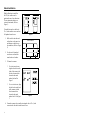
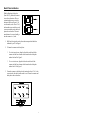
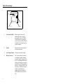
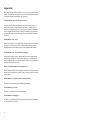
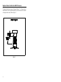
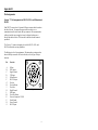
METROLOGIC INSTRUMENTS, INC.
TECH 7™ Laser Bar Code
Projection Scanner
Installation and User’s Guide
MLPN 2159
Printed in USA
June 1998
Table of Contents
Introduction . . . . . . . . . . . . . . . . . . . . . . . . . . . . . . . . . . . . . . . . . . . . . . . . . .
1
Unpacking List . . . . . . . . . . . . . . . . . . . . . . . . . . . . . . . . . . . . . . . . . . . . . . . .
1
Scanner Installation . . . . . . . . . . . . . . . . . . . . . . . . . . . . . . . . . . . . . . . . . . . . . 2
Configuration to the Host System . . . . . . . . . . . . . . . . . . . . . . . . . . . . . . . . . . 3
Stand Installation . . . . . . . . . . . . . . . . . . . . . . . . . . . . . . . . . . . . . . . . . . . . . . . 4
Back Plate Installation . . . . . . . . . . . . . . . . . . . . . . . . . . . . . . . . . . . . . . . . . . 5
Parts of the Scanner . . . . . . . . . . . . . . . . . . . . . . . . . . . . . . . . . . . . . . . . . . . . . 6
Visual Indicators . . . . . . . . . . . . . . . . . . . . . . . . . . . . . . . . . . . . . . . . . . . . 7-10
Labels . . . . . . . . . . . . . . . . . . . . . . . . . . . . . . . . . . . . . . . . . . . . . . . . . . . . . . . 11
Depth of Scan Field for the MS770 Scanner . . . . . . . . . . . . . . . . . . . . . . . . 12
Depth of Scan Field for the MS775 Scanner . . . . . . . . . . . . . . . . . . . . . . . . 13
Applications and Protocols . . . . . . . . . . . . . . . . . . . . . . . . . . . . . . . . . . . . . . 14
Maintenance . . . . . . . . . . . . . . . . . . . . . . . . . . . . . . . . . . . . . . . . . . . . . . . . . . 14
Appendix A
Specifications . . . . . . . . . . . . . . . . . . . . . . . . . . . . . . . . . . . . . . 15, 16
Appendix B
Pin Assignments . . . . . . . . . . . . . . . . . . . . . . . . . . . . . . . . . . . . 17, 18
Appendix C
Warranty and Disclaimer . . . . . . . . . . . . . . . . . . . . . . . . . . . . . 19, 20
Appendix D
Notices . . . . . . . . . . . . . . . . . . . . . . . . . . . . . . . . . . . . . . . . . . . 21, 22
Appendix E
Patents . . . . . . . . . . . . . . . . . . . . . . . . . . . . . . . . . . . . . . . . . . . . . . . 23
Index . . . . . . . . . . . . . . . . . . . . . . . . . . . . . . . . . . . . . . . . . . . . . . . . . . . . 24, 25
iii
Introduction
Metrologic’s TECH 7 laser bar code projection scanner is encased in an
NEMA-12 steel case. The case construction enables the scanner to operate in
harsh surroundings, especially industrial environments. Water-resistant,
shock-resistant, and rugged, the TECH 7 is also fast, aggressive and reliable. It
can register bar codes at a range of 76mm - 254mm (3" - 10") and can
autodiscriminate among all common codes.
To suit particular applications, two different scan patterns are available: an
omnidirectional pattern of 20 interlocking lines (Model MS770); or a 12-line
raster pattern (Model MS775). The scanner has a VLD design, a scan speed of
up to 2000 lines per second, and uses less than 8 watts of power.
Other features include an Application Specific Integrated Circuit (ASIC) and
MECCA© (Metrologic Enhanced Code Correcting Algorithm). An Application
Specific Integrated Circuit (ASIC) is in the decoding system and virtually
eliminates misreads. MECCA© (Metrologic Enhanced Code Correcting
Algorithm) enables the TECH 7 scanner to read poorly printed, wrinkled or
even torn bar codes on the first pass.
Unpacking List
The shipping carton, should contain the following:
! Installation and User’s Guide (MLPN: 2159)
! ScanSelect Scanner Programming Guide (MLPN: 2186)
! TECH 7 Model MS770 with omnidirectional scan pattern or
TECH 7 Model MS775 with raster scan pattern
! Communication Cable with Power Supply (optional) or
Communication Cable (optional)
! Back Plate (optional) or Stand (optional)
If any item is missing or to order additional items, contact the dealer, distributor or call Metrologic’s Customer Service Department at 1-800-IDMETRO or 1-800-436-3876.
1
Scanner Installation
To maintain compliance with applicable standards, all circuits connected to the
scanner must meet the requirements for SELV (Safety Extra Low Voltage)
according to EN 60950. To avoid potential problems, do not power up the
scanner until the communication cable is secured to the host.
1. "Power off" the host system.
2. Locate the 19-pin female end of the scanner link cable and find the
widest key located above pins L and A. Align this key with the
corresponding key on the scanner box’s Mil spec connector. While
pushing in on the connector, rotate the ring clockwise until it locks into
place with a click.
3. Connect the other end of the communication cable to the host device. (If
the scanner is powered by the host, skip to Step 5.)
4. Check the AC input requirements of the transformer/power supply to
make sure the voltage matches an available AC outlet. Plug the
transformer into the AC outlet to supply power to the scanner. (A
socket-outlet shall be installed near the equipment and shall be easily
accessible.)
5. "Power up" the host system.
Note: When the scanner first receives power, the LEDs will flash and
then the scanner will beep once. After the scanner performs this
startup sequence, the green LED will remain on for a specified
time indicating that the laser is on.
2
Configuration to the Host System
The scanner is shipped from the factory programmed to a set of default
conditions noted in the ScanSelect Scanner Programming Guide by an asterisk
that appears before the brief definition located next to the bar code.
In order for the scanner to communicate with a host system properly, it may
need to be programmed. Since each host system is unique, configure the
scanner to match the host system requirements. Configure the scanner by
entering the program mode and scanning the appropriate bar codes that appear
in the ScanSelect Scanner Programming Guide. (To use ScanSet™, refer to
the ScanSet documentation for information on how to configure a scanner.)
1. Connect the scanner to the host system (Refer to the Scanner
Connections to the Host section in this guide).
2. Enter program mode by scanning the ENTER/EXIT program mode bar
code. (The unit will beep three times)
3. Scan the appropriate bar code(s) that appear in the ScanSelect Scanner
Programming Guide. (Reveal only one bar code to the scanner each
time. With your hand, cover the bar code not to be scanned.)
4. Exit program mode by scanning the ENTER/EXIT program mode bar
code again. (The new options will be saved and the scanner is ready for
normal operation.)
3
Stand Installation
With the Metrologic stand (Part
#45475), the scanner can be
positioned in one of two directions.
The two orientation choices are
vertical or horizontal. (Refer to
Figure 1)
To install this stand, use the four 632 x ½ inch machine screws and two
#10 panhead wood screws.
1. Drill two holes into the work
surface that are the same size
and distance as the holes on
the stand base. (Refer to Figure
2)
Figure 1
Base of Stand
2. Use the two #10 panhead
wood screws to attach the
stand to the work surface.
Figure 2
3. To fasten the scanner:
! For a horizontal mount,
align the four holes on the
back of the scanner with
the four clearance holes
located on the stand
marked with an X in
Figure 3.
! For a vertical mount, align
the four holes on the back
of the scanner with the
four clearance holes
located on the stand
marked with a Y in Figure
3.
Figure 3
4. Fasten the scanner to the stand by inserting the four 6-32 x ½ inch
screws into the four holes in the scanner’s case.
4
Back Plate Installation
With the Metrologic back plate
(Part #45473), position the scanner
in one of two directions. The two
orientation choices are vertical or
horizontal. (Refer to Figure 4). To
use this stand, use the four 6-32 x ½
inch machine screws and four wood
screws to attach the unit to the back
plate and work surface. The maximum distance the screws should go
into the scanner is a ½ inch.
Figure 4
1. Drill four holes into the work surface that correspond with the holes
indicated by an XY in Figure 5.
2. To fasten the scanner to the back plate:
! For a horizontal mount, align the four holes on the back of the
scanner with the four clearance holes located on the back plate
marked with an X in Figure 5.
! For a vertical mount, align the four holes on the back of the
scanner with the four clearance holes located on the back plate
marked with a Y in Figure 5.
3. Fasten the scanner to the back plate by inserting the four 6-32 x ½ inch
screws into the four holes in the scanner’s case. Fasten the scanner and
back plate to the work surface.
Figure 5
5
Parts of the Scanner
1 Green and
Red LEDs
2 Speaker
3 Laser Output Window
4 Mil spec Connector
Figure 6
6
1
Green and Red LEDs
When the green LED is on, this
indicates that the unit is receiving
power and the laser is on. When the
red LED flashes on, the scanner has
read a bar code successfully. When the
red light turns off, communica-tion to
the host is complete.
2
Speaker
The speaker emits a beep when a bar
code has been decoded.
3
Laser Output Window
This aperture emits the laser light.
4
Mil spec Connector
The 19-pin male Mil spec connector
was designed to connect a communi
cation cable from the scanner to a host
device. The communication cable may
include a power supply or it may be de
signed to draw power directly from the
host device. The standard TECH 7 has
one connector. (When atrium option is
installed, a second connector is
installed on the unit to connect the
MX001 Industrial Control Interface
box.)
Visual Indicators
There is a red and green LED at the top of the scanner. When the scanner is
on, the flashing or stationary activity of the LEDs indicates the status of the
scan and scanner.
Steady Green
When the laser is on, the green LED is also on. This occurs when an object is
in the scan field.
Steady Green; Red Flash
When the scanner successfully reads a bar code, the red LED will flash then
beep once. If the red LED does not flash or the scanner does not beep once,
then the bar code has not been successfully read.
Steady Red and Green
After a successful scan, the scanner transmits the data to the host device. When
the host is not ready to accept the information, the scanner’s red LED will
remain on until the data can be transmitted.
Alternating Red and Green
This indicates the scanner is in program mode.
Steady Red
This indicates the scanner is in ScanSet mode.
No Red or Green LED
There are two reasons why the LEDs will not be illuminated. First, if the
scanner is receiving power and the LEDs are not on, then the scanner has
remained dormant for a specified time and the laser has turned off. To
reactivate the unit, touch the touch plate. Secondly, if the scanner is not
receiving power from the host or transformer, then the LEDs will not turn on.
Flashing Red
This indicates the scanner has experienced a laser subsystem failure. Return
the unit for repair at an authorized service center.
7
Signaux optiques
Sur la partie supérieure du scanner se trouvent une diode LED rouge et une diode LED
verte. Quand le scanner est sous tension, les diodes rouge et verte clignotantes ou
allumées vous informent sur l'état du scanner.
Ni la diode rouge, ni la diode verte n'est allumée
Il existe deux raisons possibles pour que les diodes ne s'allument pas. Premièrement: si
le scanner reçoit de l'énergie sans que les diodes ne s'allument, le scanner est resté sans
servir pendant une certaine période et le laser est désactivé. Pour le réactiver, passer un
objet devant le palpeur infrarouge. Deuxièmement: quand le scanner ne reçoit de
l'énergie ni de l'ordinateur central, ni du transformateur, les diodes restent éteintes.
La diode verte reste allumée
Quand le laser est en service, la diode verte s'allume également. C'est le cas quand un
objet se trouve devant le palpeur. La diode verte reste allumée tant que la temporisation
de l'infrarouge dure ou jusqu'à ce que le scanner soit désactivé.
La diode verte reste allumée; la diode rouge clignote
Après lecture avec succès d'un code à barres par le scanner, la diode rouge se met à
clignoter, suivie d'un bip sonore unique. Si la diode rouge ne clignote pas ou quand
aucun bip sonore n'est émis, cela signifie que le code à barres n'a pas pu être lu avec
succès.
Les diodes rouges et vertes restent allumées
Une fois la lecture effectuée avec succès, le scanner transmet les données à l'ordinateur
central. Si ce dernier n'est pas prêt à recevoir les données, la diode rouge du scanner
reste allumée jusqu'à ce que les données puissent être transmises.
Les diodes rouges et vertes clignotent en alternance
Indique que le scanner se trouve en mode de programmation.
La diode rouge reste allumée
Indique que le scanner se trouve en mode ScanSet.
Diode rouge clignotante
Indique une panne de laser pendant la lecture. Veuillez envoyer votre appareil chez
unconcessionnaire pour réparation.
8
Optische Anzeigen
Auf dem Scanner befinden sich eine rote und eine grüne Leuchtdiode. Bei
eingeschaltetem Scanner geben Ihnen die blinkenden bzw. feststehenden
Leuchtdiodenanzeigen Aufschluß über den Abtast- und Scannerstatus.
Weder rote noch grüne Leuchtdiodenanzeige
Es gibt zwei mögliche Gründe, weshalb die Leuchtdiodenanzeigen nicht aufleuchten.
Erstens: Wenn der Scanner mit Energie versorgt wird und die Leuchtdiodenanzeigen
nicht aufleuchten, so ist der Scanner für einen bestimmten Zeitraum untätig geblieben,
und der Laser ist abgeschaltet. Zur Reaktivierung der Einheit sollten Sie ein Objekt vor
dem Infrarot-Sensor hin- und herbewegen. Zweitens: Wenn der Scanner weder vom
Hostrechner noch vom Transformator Energie erhält, so leuchten die
Leuchtdiodenanzeigen nicht auf.
Feststehende grüne Anzeige
Wenn der Laser in Betrieb ist, leuchtet die grüne Leuchtdiodenanzeige ebenfalls auf.
Dies ist dann der Fall, wenn sich ein Objekt im Abtastfeld befindet. Die grüne
Leuchtdiodenanzeige leuchtet solange auf, bis das Infrarot-Timeout abgelaufen ist, oder
bis der Scanner abgeschaltet wird.
Feststehende grüne Leuchtanzeige; rote Blinkanzeige
Nach erfolgreichem Lesen eines Barcodes durch den Scanner blinkt die rote
Leuchtdiodenanzeige auf, gefolgt von einem einmaligen Piep-Signal. Blinkt die rote
Leuchtdiodenanzeige nicht auf oder sendet der Scanner kein Piep-Signal aus, so konnte
der Barcode nicht erfolgreich gelesen werden.
Feststehende rote und grüne Leuchtanzeige
Nach erfolgreichem Abtasten überträgt der Scanner die Daten an das Hostgerät. Falls
das Hostgerät zur Datenannahme nicht bereit ist, leuchtet die rote Leuchtdiodenanzeige
des Scanners solange auf, bis die Daten übertragen werden können.
Alternierende rote und grüne Leuchtanzeige
Zeigt an, daß sich der Scanner im Programmiermodus befindet.
Feststehende rote Leuchtanzeige
Zeigt an, daß sich der Scanner im ScanSet-Modus befindet.
Aufblinkende rote Leuchtanzeige
Zeigt an, daß beim Scanner ein Laserausfall vorliegt. Bringen Sie das Gerät zur
Reparatur in ein Vertragsservicecenter.
9
Segnali ottici
Sullo scanner si trovano due diodi luminosi: uno rosso e uno verde. Quando lo scanner
è inserito, i diodi luminosi, che possono o essere accesi in continuazione o lampeggiare,
Vi informano sullo stato della scansione e dell’apparecchio.
Né il diodo luminoso rosso né quello verde sono accesi
Vi sono due possibili cause se i diodi luminosi non sono accesi. Prima causa: se lo
scanner viene alimentato e i diodi luminosi non sono accesi, lo scanner è rimasto
disattivato per un determinato periodo e il laser è spento. Per riattivare l’unità dovreste
muovere un oggetto davanti al sensore a infrarossi. Seconda causa: se lo scanner non
viene alimentato né dal calcolatore host né dal trasformatore, i due diodi luminosi non
sono accesi.
Il diodo luminoso verde è acceso
Quando il laser è inserito, è acceso anche il diodo luminoso verde. Questo si ha quando
un oggetto si trova nella zona di scansione. Il diodo luminoso verde è acceso fino al
raggiungimento del timeout infrarossi oppure fino allo spegnimento dello scanner.
Il diodo luminoso verde è acceso; quello rosso lampeggia
Dopo la lettura riuscita di un codice a barre da parte dello scanner il diodo luminoso
rosso lampeggia e quindi viene emesso un unico segnale beep. Se il diodo luminoso
rosso non lampeggia oppure lo scanner non emette un segnale beep, ciò significa che la
lettura del codice a barre non è riuscita.
Sono accesi sia il diodo luminoso rosso che quello verde
Dopo la scansione riuscita lo scanner trasmette i dati all’host. Se l’host non è pronto per
accettare i dati, il diodo luminoso rosso dello scanner è acceso fino a che i dati possono
essere trasmessi.
Il diodo luminoso rosso e quello verde sono accesi in alternanza
Ciò indica che lo scanner si trova nella modalità di programmazione.
Il diodo luminoso rosso è acceso
Ciò indica che lo scanner si trova nella modalità ScanSet.
Il diodo luminoso rosso lampeggia
Ciò indica che lo scanner ha un guasto a livello del laser. Fate riparare l’apparecchio da
un centro di assistenza autorizzato.
10
Labels
There is one label located inside the window of the scanner noting that this
device is a CDRH Class IIa laser product and IEC 825 LASERKLASSE 1.
Also, on the scanner is a label located on the back of the unit. This label
contains information such as the model number, date of manufacture, serial
number, and approvals. The following are samples of the labels located on the
unit.
11
Depth of Scan Field for the MS770 Scanner
The depth of field for the scanner is 76mm to 254mm (3" - 10") from the laser
output window. Pass the symbol through the scan area in order for the scanner
to recognize the bar code. (Refer to Figure 7)
Figure 7
12
Depth of Scan Field for the MS775 Scanner
The depth of field for the scanner is 76mm to 254mm (3" - 10") from the laser
output window. Pass the symbol through the scan area in order for the scanner
to recognize the bar code. (Refer to Figure 8)
Figure 8
13
Maintenance
Smudges and dirt can interfere with the proper scanning of a bar code.
Therefore, the output window will need occasional cleaning.
1. Spray glass cleaner onto lint free, nonabrasive cleaning cloth.
2. Gently wipe the output window.
Applications and Protocols
The model number on each scanner includes the scanner number and
communications protocol.
Version Identifier
1
15
14
Communication Protocol(s)
RS-232, OCIA, Bidirectional RS-232
Light Pen Emulation
Appendix A
Specifications
Application:
Light Source:
Laser Class:
Certifications:
EMC:
Industrial Projection Scanner
Visible Laser Diode 670 ± 5nm,
CDRH: CLASS IIa; EN 60825 Class 1
CE, UL listed for US and Canada
FCC Class A, CISPR Class A
Mechanical
Dimensions:
Weight:
Orientation:
Mounting:
Top Cover:
Host Cable Length:
184mmL x 186mmW x 78mmD
(7.25"L x 7.3"W x 3.06"D)
2.35 kg. (5.19 lbs.) without cable
May be used in any orientation
Back plate mount or Vertical stand
NEMA-12 steel case
1.83m (6') cable with mil spec connector
Electrical
Power Consumption:
Input Voltage:
Operating Current:
Standby Current:
DC Transformers:
8 watts, host system or wall transformer
11-30 VDC
420mA typical @ 20V
210mA typical @ 20V
120V (AC in), 230V (AC in), 240V ( AC in);
output 20V @ 750mA
Patents Pending
Specifications subject to change without notice.
15
Operational
Depth of Scan Field:
Scan Speed:
Scan Pattern:
Indicators:
Beeper Operation:
Maintenance Required:
Decode Capability:
System Interfaces:
Optional:
Print Contrast:
Roll, Pitch, Yaw:
76mm to 254mm (3" to 10")
Model 770: 2000 scan lines per second
Model 775: 1200 scan lines per second
Model 770: Omnidirectional
(20 interlocking lines)
Model 775: 12-line raster
LED: green = laser on; red = good read
Selection of 3 tones for “Good Read”
Clean window periodically
Autodiscriminates
RS232C; Light Pen Emulation; OCIA
Opto coupled 6 amps US and Canada, 5 amps
EEA countries TRIAC output; object sensor input
35% minimum reflectance difference
360E, 60E, 60E
Environmental
Storage Temperature:
Operating Temperature:
Humidity:
Light Levels:
Ventilation:
Shock:
ESD:
Contaminants:
-40EC to 60EC (-40EF to 140EF)
0EC to 35EC (32EF to 95EF)
5% to 95% relative humidity, non-condensing
Up to 3200 foot candles - works in direct sun
None required
100g for 1ms
8 kV IEC 801-2
Protects against dust, falling dirt, and dripping
non-corrosive liquid
Specifications subject to change without notice.
16
Appendix B
Pin Assignments
Version “1” Pin Assignments for RS-232, OCIA, and Bidirectional
RS-232
Each TECH 7 scanner has a 19-pin male Mil spec connector that is located on
the side of the unit. To connect the scanner to the host device, use a
communication cable with a female Mil spec connector. The communication
cable may include a power supply or it may be designed to draw power
directly from the host device. This item can be ordered when the scanner is
purchased.
The Version “1” scanner is designed to be used for RS-232, OCIA, and
RS-232 with limited receiving capabilities.
The following is a list of pin assignments. The pin numbers are impressed on
the male Mil spec connector. For easier reference, refer to Figure 9 for pin
locations.
Pin
Function
A
B
C
D
E
F
G
H
J
K
L
M
N
P
R
S
R Data
RTS Output
Signal Ground
CTS Input
R Data Return
RS-232 Output
Clock in
Clock in Return
Clock Out
Shield Ground
DTR Input
Clock Out Return
Power to Scanner & 24 VDC
Earth Ground
Power Ground
RS-232 Input
Figure 9
17
Version “15” Pin Assignments for Light Pen Emulation
Each TECH 7 scanner has a 19-pin male Mil spec connector that is located on
the side of the unit. To connect the scanner to the host device, use a
communication cable with a female Mil spec connector. The communication
cable may include a power supply or it may be designed to draw power
directly from the host device. This item can be ordered when the scanner is
purchased.
The Version “15” scanner is designed to be used for Light Pen Emulation
communication.
The following is a list of pin assignments. The pin numbers are impressed on
the male Mil spec connector. For easier reference, refer to Figure 10 for pin
locations.
Pin
A
B
C
D
E
F
G
H
J
K
L
M
N
P
R
S
18
Function
R Data
Light Pen Data Output
Signal Ground
Light Pen Source & 5
VDC
R Data Return
RS-232 Output
Clock in
Clock in Return
Clock Out
Shield Ground
DTR Input
Clock Out Return
Power to Scanner & 24 VDC
Earth Ground
Power Ground
RS-232 Input
Figure 10
Appendix C
Warranty and Disclaimer
Limited Warranty
Products manufactured by Metrologic have a 2-year limited warranty from
date of manufacture.
This warranty is limited to repair, replacement or refund at Metrologic’s
discretion. Faulty equipment must be returned to the Metrologic facility in
Blackwood, New Jersey or Puchheim, Germany. To do this, contact
Metrologic Customer Service/Repair for a Returned Material Authorization
(RMA) number.
In the event that it is determined that the equipment failure is covered under the
warranty, Metrologic shall, as its sole option, repair, replace with a functionally
equivalent unit, or refund an amount equal to the purchase price to the original
purchaser, whether distributor, dealer/reseller, or retail consumer, and return the
equipment to the customer without charge for service or return freight.
This limited warranty does not extend to any Product which, in the sole judge-ment
of Metrologic, has been subjected to misuse, neglect, improper installation or
accident, nor does it extend to any Product which has been repaired or altered by
anyone who is not a Metrologic authorized representative.
THIS LIMITED WARRANTY, EXCEPT AS TO TITLE, IS IN LIEU OF ALL
OTHER WARRANTIES, EXPRESS OR IMPLIED, INCLUDING
MERCHANTABILITY OR FITNESS FOR ANY PARTICULAR PURPOSE,
ARISING BY LAW, CUSTOM OR CONDUCT. THE RIGHTS AND
REMEDIES PROVIDED HEREIN ARE EXCLUSIVE AND IN LIEU OF ANY
OTHER RIGHTS OR REMEDIES. IN NO EVENT SHALL METROLOGIC BE
LIABLE FOR INDIRECT, INCIDENTAL, OR CONSEQUENTIAL DAMAGES,
INCLUDING, WITHOUT LIMITATION, ANY INJURY TO PROPERTY OR
PERSON OR EFFECT ON BUSINESS OR PROFIT, AND IN NO EVENT
SHALL ANY LIABILITY OF METROLOGIC EXCEED THE ACTUAL
AMOUNT PAID TO METROLOGIC FOR THE PRODUCT.
Metrologic Instruments, Inc.
90 Coles Road
Blackwood, NJ 08012
Customer Service Department
1-800-ID-METRO (1-800-436-3876)
TEL: 609-228-8100
FAX: 609-228-6673
Metrologic Instruments GmbH
Dornierstrasse 2
82178 Puchheim b.
Munich, Germany
TEL: 49-89-89019-0
FAX: 49-89-89019-200
19
Disclaimer
Metrologic Instruments, Inc. and the author or authors make no claims or warranties with respect
to the contents or accuracy of this publication, or the product it describes, including any warranties
of fitness or merchantability for a particular purpose. Any stated or expressed warranties are in
lieu of all obligations or liability for any damages, whether special, indirect, or consequential,
arising out of or in connection with the use of this publication or the product it describes.
Furthermore, the right is reserved to make any changes to this publication without obligation to
notify any person of such changes. Metrologic also reserves the right to make any changes to the
product described herein.
Exclusion des responsabilités
Metrologic Instruments, Inc. et le/les auteur(s) ne sont ni garants, ni responsables pour l'exhaustivité et la correction des informations contenues dans cette brochure - que ce soit relativement à leur teneur et à l' exactitude - ou pour le produit qui y est décrit. Ils ne sont en outre
responsables d'aucune garantie de propriété ou de qualité pour un usage particulier. Toutes les
assurances nommées ou exprimées excluent toute garantie ou responsabilité pour les dommages
spéciaux, indirects ou des suites de l'utilisation de cette brochure ou du produit qui y est décrit
respectivement. en rapport avec l'emploi de cette brochure et du produit qui y est décrit. Il leur est
également réservé le droit de procéder à des modifications de cette brochure sans avoir à en avertir
qui que ce soit. Metrologic se réserve en outre le droit de procéder à des modifications du produit
qui y est décrit.
Haftungsausschluß
Metrologic Instruments, Inc. und der/die Autor(en) übernehmen keinerlei Gewähr und haften nicht
für die Richtigkeit im Hinblick auf Inhalt oder Genauigkeit der Angaben dieser Veröffentlichung
oder des hierin beschriebenen Produkts. Sie übernehmen ebenso keinerlei Eignungsgarantie oder
Gewährleistung durchschnittlicher Qualität für einen bestimmten Zweck. Alle benannten oder
ausdrücklichen Zusicherungen schließen sämtliche Verpflichtungen oder Haftungen aus jeglichem
Schaden aus, ganz gleich ob speziell, indirekt oder als Folge der Verwendung dieser
Veröffentlichung oder des hierin beschriebenen Produkts bzw. in Zusammenhang mit der
Verwendung dieser Veröffentlichung oder des hierin beschriebenen Produkts. Darüber hinaus wird
das Recht vorbehalten, Änderungen an dieser Veröffentlichung vorzunehmen ohne die
Verpflichtung, irgend jemanden über solche Änderungen zu unterrichten. Metrologic behält sich
ferner das Recht vor, Änderungen an dem hierin beschriebenen Produkt vorzunehmen.
Esclusione della responsabilità
La Metrologic Instruments, Inc. e l’autore/gli autori non assumono nessuna garanzia e non
rispondono della correttezza per quanto riguarda il contenuto o la precisione di quanto indicato nel
presente Manuale o del prodotto in esso descritto. Neppure essi assumono una garanzia per
l’idoneità o una garanzia della qualità media per un determinato scopo. Tutte le garanzie citate o
fatte espressamente escludono qualsiasi obbligo o responsabilità derivanti da qualsiasi danno,
indipendentemente dal fatto che questo obbligo/questa responsabilità risulti in particolare, indirettamente o come conseguenza dall’uso del presente Manuale o del prodotto in esso descritto
oppure se è legato/a all’uso del presente Manuale o del prodotto in esso descritto. Inoltre ci si
riserva il diritto di modificare il presente Manuale senza essere obbligati ad informare persona
alcuna circa dette modifiche. Metrologic si riserva il diritto di apportare modifiche al prodotto
descritto nel presente Manuale.
20
Appendix D
Notices
Notice
This equipment has been tested and found to comply with limits for a Class A digital device,
pursuant to Part 15 of the FCC Rules. These limits are designed to provide reasonable protection
against harmful interference when the equipment is operated in a commercial environment. This
equipment generates, uses and can radiate radio frequency energy and, if not installed and used in
accordance with the instruction manual, may cause harmful interference to radio communications.
Operation of this equipment in a residential area is likely to cause harmful interference, in which
case the user will be required to correct the interference at his own expense. Any unauthorized
changes or modifications to this equipment could void the users authority to operate this device.
Notice
This digital apparatus does not exceed the Class A limits for radio noise emissions from digital
apparatus set out in the Radio Interference Regulations of the Industry and Canada.
Caution
Use of controls or adjustments or performance of procedures other than those specified herein may
result in hazardous laser light. Under no circumstances should the customer attempt to service the
laser scanner. Never attempt to look at the laser beam, even if the scanner appears to be
nonfunctional. Never open the scanner in an attempt to look into the device. Doing so could result
in hazardous laser light exposure. The use of optical instruments with the laser equipment will
increase eye hazard.
Remarque
Après contrôle de cet appareil, on a noté qu'il répondait aux valeurs limites de la classe A, conformément à la partie 15 des directives de l'administration fédérale américaine pour les télécommunications. Ces valeurs limites ont été prévues pour garantir une protection suffisante
contre les effets nocifs dus à l'emploi de l'appareil dans un magasin. L'appareil génère et utilise une
énergie haute fréquence et peut, s'il n'est pas installé et utilisé conformément aux instructions
mentionnées dans le guide d'utilisation, entraîner des perturbations dans la radiocommunications.
L'utilisation de cet appareil dans une zone d'habitation entraînera très vraisemblablement des
perturbations. Dans ce cas, l'utilisateur est tenu de remédier à ces perturbations à ses propres frais.
Toute modification ou remplacement non autorisé sur cet appareil peut entraîner l'invalidité de
l'autorisation d'utilisation de l'appareil.
Remarque
Cet appareil numérique ne va pas contre les valeurs limites pour émissions de bruits radios des
appareils numérique de la classe A, conformément aux directives relatives aux perturbations des
radiocommunications du ministère canadien pour l'industrie.
Attention
L'emploi de commandes, réglages ou procédés autres que ceux décrits ici peut entraîner de graves
irradiations. Le client ne doit en aucun cas essayer d'entretenir lui-même le scanner ou le laser. Ne
regardez jamais directement le rayon laser, même si vous croyez que le scanner est inactif.
N'ouvrez jamais le scanner pour regarder dans l'appareil. Ce faisant, vous vous exposez à une
rayonnement laser mortel. L'emploi d'appareils optiques avec cet équipement laser augmente le
risque d'endommagement de la vision.
21
Anmerkung
Nach Überprüfung dieses Geräts wurde festgestellt, daß es den Grenzwerten für Digitalgeräte der
Klasse A gemäß Teil 15 der Richtlinien der US-amerikanischen Bundesbehörde für das
Fernmeldewesen entspricht. Diese Grenzwerte wurden festgelegt, um einen angemessenen Schutz
gegen schädliche Auswirkungen bei Einsatz des Geräts in einer Ladenumgebung zu gewähren.
Das Gerät erzeugt und verwendet Hochfrequenzenergie und kann diese ausstrahlen, und kann,
falls es nicht gemäß den im Bedienerhandbuch enthaltenen Anweisungen installiert und verwendet
wird, zu einer Störung des Funkverkehrs führen. Der Betrieb dieses Geräts in einem Wohngebiet
führt höchstwahrscheinlich zu Störungen. In diesem Fall ist der Bediener verpflichtet, die Störung
auf eigene Kosten zu beseitigen. Durch jegliche unerlaubte Auswechselung oder Änderung an
diesem Gerät könnte die Genehmigung des Bedieners zur Verwendung dieses Geräts ungültig
werden.
Anmerkung
Dieses Digitalgerät verstößt nicht gegen die Grenzwerte für Funkrauschemissionen von
Digitalgeräten der Klasse A gemäß den Richtlinien für Funkstörungen des kanadischen
Ministeriums für Industrie.
Achtung
Die Verwendung anderer als der hierin beschriebenen Steuerungen, Einstellungen oder Verfahren
kann eine lebensgefährliche Laserstrahlung hervorrufen. Der Kunde sollte unter keinen
Umständen versuchen, den Laser-Scanner selbst zu warten. Sehen Sie niemals in den Laserstrahl,
selbst wenn Sie glauben, daß der Scanner nicht aktiv ist. Öffnen Sie niemals den Scanner, um in
das Gerät hineinzusehen. Wenn Sie dies tun, können Sie sich einer lebensgefährlichen
Laserstrahlung aussetzen. Der Einsatz optischer Geräte mit dieser Laserausrüstung erhöht das
Risiko einer Sehschädigung.
N.B.
Dal controllo di questo apparecchio risulta che esso risponde ai valori limite per apparecchi
digitali della classe A conf. parte 15 delle direttive sulle telecomunicazioni dell’Autorità federale
statunitense. Questi valori limite sono stati fissati per garantire una protezione adeguata contro gli
effetti nocivi se questo apparecchio viene usato all’intero di un negozio. L’apparecchio genera,
utilizza e può emettere energia ad alta frequenza e, se non viene installato ed utilizzato
conformemente alle indicazioni fornite nel Manuale utente, può provocare disturbi al servizio
radiofonico. L’uso di questo apparecchio in zone residenziali causa molto probabilmente dei
disturbi. In questo caso l’utente è obbligato ad eliminare questi disturbi a sue spese. Qualsiasi
sostituzione o modifica non autorizzata all’apparecchio potrebbe rendere invalida l’autorizzazione
dell’utente all’uso dell’apparecchio.
N.B.
Questo apparecchio digitale non supera I valori limite per l’emissione di radiorumori da parte di
apparecchi digitali della classe A conformemente alle direttive per radiodisturbi del Ministero
canadese per l’Industria.
Attenzione
L’utilizzo di sistemi di controllo, di regolazioni o di procedimenti diversi da quelli decritti nel
presente Manuale può provocare dei raggi laser pericolosi per la vita. Il cliente non deve
assolutamente tentare di riparare egli stesso lo scanner laser. Non guardate mai nel raggio laser,
anche se credete che lo scanner non sia attivo. Non aprite mai lo scanner per guardare dentro
l’apparecchio. Se tuttavia lo fate, potete esporVi a dei raggi laser pericolosi per la vita. L’uso di
apparecchi ottici con questo equipaggiamento laser aumenta il rischio di danni alla vista.
22
Appendix E
Patents
“Patent Information
This METROLOGIC product may be covered by one or more of the following
U.S. Patents:
U.S. Patent No. 4,360,798; 4,369,361; 4,387,297; 4,460,120; 4,496,831;
4,593,186; 4,607,156; 4,673,805; 4,736,095; 4,758,717; 4,816,660;
4,845,350; 4,896,026; 4,923,281; 4,933,538; 4,992,717; 5,015,833;
5,017,765; 5,059,779; 5,117,098; 5,124,539; 5,130,520; 5,132,525;
5,140,144; 5,149,950; 5,180,904; 5,200,599; 5,229,591; 5,247,162;
5,250,790; 5,250,791; 5,250,792; 5,262,628; 5,280,162; 5,280,164;
5,304,788; 5,321,246; 5,324,924; 5,396,053; 5,396,055; 5,408,081;
5,410,139; 5,436,440; 5,449,891; 5,468,949; 5,479,000; 5,532,469;
5,545,889
No license right or sublicense is granted, either expressly or by implication,
estoppel, or otherwise, under any METROLOGIC or third party intellectual
property rights (whether or not such third party rights are licensed to
METROLOGIC), including any third party patent listed above, except for an
implied license only for the normal intended use of the specific equipment,
circuits, and devices represented by or contained in the METROLOGIC
products that are physically transferred to the user, and only to the extent of
METROLOGIC’s license rights and subject to any conditions, covenants and
restrictions therein.”
23
Index
A
AC
2, 15
Application 15
Application and protocols
Asia
ii
ASIC 1
Europe ii
14
B
Back plate
hortizontal mount 5
vertical mount 5
Bar code(s) 1, 3, 6, 7, 12-14
Beep
2, 3, 6, 7, 10, 16
Beeper operation 16
C
Cable
F
Faulty equipment 19
Fax
ii
G
Germany (GmbH)
Good read
16
Green LED
2, 6, 7
ii, 19
H
Headquarters
ii
Host
2, 3, 6, 7, 9, 10, 15, 17,
18
Humidity
16
communication 1, 2, 6,
17, 18
length 15
CDRH class IIa 11
Clean 14, 16
Communication protocol 14
Compliance 2
Configuration 3
Contrast 16
Copyright ii
Current 15
Customer Service ii, 19
D
Depth of field
Dimensions
Disclaimer
E
Electrical
EMI
15
Email ii
Environmental
ESD
16
24
12, 13
15
20
15
16
I
IEC 825 LASERKLASSE 1 11
Indicators
LED 2, 6, 7, 16
Visual 4-10
Interfaces
14, 16
Installation
Back plate
5
Scanner
2
Stand
4
Internet ii
Introduction
1
L
Labels 11
LEDs 2, 6, 7, 16
Light levels
16
Light pen emulation
16, 18
Light source
15
Limited warranty 19
List
1
Locations
ii
14,
M
Maintenance
14, 16
MECCA
1
Mechanical
15
Mil spec connector
15, 17, 18
Model number 11, 14
Mounting 4, 5, 15
MS770 1, 12
MS775 1, 13
N
NEMA-12 steel case
Notices 21, 22
2, 6,
1, 15
O
OCIA 14, 16, 17
Operating current 15
Operating temperature
16
Operation
3, 16
Operational
16
Output window 6, 12-14, 16
P
Parts
6
Patents 23
Print contrast
16
Programming guide
Protocols
14
R
Red LED
6, 7
Repair 19
Rights
property
23
warranty
19
RMA 19
Roll, pitch, yaw 16
RS-232 14, 16-18
Scan field
12, 13, 16
Scan lines
16
Scan pattern
1, 16
Scan speed
1, 16
ScanSelect
1, 3
ScanSet 3, 7-9
Service 19
Shipping carton 1
Shock 16
South America ii
Speaker 6
Specifications
15, 16
Stand 1, 4, 5, 15
hortizontal mount 4
vertical mount 4
Storage temperature
16
System interfaces 16
T
Temperature
Tones 16
Transformer
16
2, 7, 15
U
UL/CSA/TUV/CE
15
USA corporate headquarters
ii
1, 3
V
Ventilation
16
Version “1"
17
Version “15"
18
Version identifiers
Voltage 2, 15
14
W
Warranty
19
Watts 1, 15
Weight 15
Window 6, 12-14, 16
S
25