1
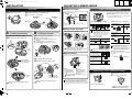
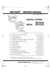
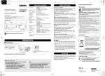
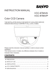
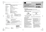
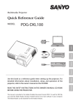
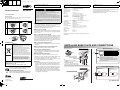
L5CJ2_XE(VCC-9685VP)(GB).fm 1 ページ
English
Deutsch
2007年10月26日 金曜日 午後4時9分
Français
PRECAUTIONS
Important
INSTRUCTION MANUAL
VCC-9685VP
• Be careful when opening holes for installing the unit. Work with the
power and video cables pulled out for easy installation.
• Make sure to properly perform waterproofing for the ceiling or wall
where you are installing the unit.
Color CCD Camera
• Make sure that the surface in the installation location has no
unevenness and is strong enough to bear the total weight of the unit.
About this manual
• Install this unit in an environment where the temperature range stays
between -10°C and +50°C/14°F and 122°F (no condensation allowed).
Before installing and using the camera, please read this manual carefully.
Be sure to keep it handy for later reference.
Wall Installed
In-ceiling routing
Ceiling Installed
• As a precaution against static electricity damage, touch a nearby metal
object (door knob, etc.) to dissipate static electricity in your body before
touching this unit.
■ In case of a problem
Surface routing*1
Do not use the unit if smoke or a strange odor comes from the unit,
or if it seems not to function correctly. Turn off the power
immediately and disconnect the power cord, and then consult your
dealer or an Authorized Sanyo Service Center.
■ Do not open or modify
Do not open the cabinet, as it may be dangerous and cause damage
to the unit. For repairs, consult your dealer or an Authorized Sanyo
Service Center.
■ Do not put objects inside the unit
*1 Surface routing
SPECIFICATIONS
Scanning system
Image sensor
Number of effective pixels
Horizontal resolution
Minimum illumination
(approx.)
Video output
Video S/N ratio
Vari-focal lens
Rotation range
Backlight compensation
White balance
Electronic shutter
Aperture compensation
Sync system
Operating Environment
Power supply
Power consumption
(approx.)
Weight (approx.)
Accessory
:
:
:
:
SERVICE
PAL standard 625 lines, 50 fields/sec.
1/4" interline transfer method CCD
752 (H) x 582 (V)
540 TV lines, typical
: 0.5 lx (F0.95)
: 1.0 V(p-p)/75 Ω, composite, BNC
UTP support (VA-10T: option board)
: More than 48 dB (AGC off: More than 50 dB)
: f2.8 - 8 mm, F=0.95 - 1.7
: (On the ceiling) Pan: ± 100 degrees
Tilt: 0 - 90 degrees
(On the wall)
Pan: ± 90 degrees
Tilt: 0 - 90 degrees
: OFF, Multi-spot metering (High/Normal), Center zone
metering
: ATW/Manual
: 1/50, 1/120, 1/1000, 1/2000 sec.
: Sharp/Normal
: Internal sync/Line-lock
: Temperature: –10°C – +50°C (14°F – 122°F)
Humidity: less than 90 % RH (no condensation)
: 24 V AC ±10%, 50 Hz / 12 - 15 V DC
The camera is a precision instrument. Handle it carefully and always
follow the safety precautions. If the camera requires service, never
try to repair it yourself or open the casing.
For servicing, maintenance, or repairs, consult your dealer or an
Authorized Sanyo Service Center.
: 2.4 W
: 500 g (16 oz.)
: Screw ×1
Appearance and specifications are subject to change without prior notice
or obligations.
Make sure that no metal objects or flammable substance get inside
the unit. If used with a foreign object inside, it could cause a fire, a
short-circuit or damage. Be careful to protect the unit from rain, sea
water, etc. If water or liquid gets inside the unit, turn off the power
immediately and disconnect the power cord, and then consult your
dealer or an Authorized Sanyo Service Center.
Cutout
Rib mark
For EU Users
■ Be careful when handling the unit
Please note:
Your SANYO product is designed and manufactured
with high quality materials and components which
can be recycled and reused.
This symbol means that electrical and electronic
equipment, at their end-of-life, should be disposed
of separately from your household waste.
Please dispose of this equipment at your local
community waste collection/recycling centre.
In the European Union there are separate collection
systems for used electrical and electronic products.
Please help us to conserve the environment we live
in!
This symbol mark and recycle system are
applied only to EU countries and not applied
to countries in other areas of the world.
SANYO FISHER Sales (Europe) GmbH
Stahlgruberring 4, D-81829 München, Germany
SANYO Electric Co., Ltd.
1-1, Sanyo-cho, Daito City, Osaka 574-8534, Japan
For Russian Users
This product certified by official certification company
which is authorized by Russian Federation.
ДЛЯ ПОЛЬЗОВАТЕЛЕЙ РОССИЯ
Данная продукция сертифицирована официальным
органом по сертификации Российской Федерации.
To prevent damage, do not drop the unit or subject it to strong shock
or vibration.
■ Do not install this unit close to magnetic fields
INSTALLING BASE PLATE AND CONNECTIONS
The magnetic fields may result in unstable operation.
■ Protect from humidity and dust
Open the base plate.
Ceiling Installed
Monitor Connection
(B)
(C)
To prevent damage, do not install the unit where there is greasy
smoke or steam, where the humidity may get too high, or where
there is a lot of dust.
Cable type
RG-59U (3C-2V)
RG-6U (5C-2V)
RG-11U (7C-2V)
(B)
Push
■ Protect from high temperatures
Do not install close to stoves, or other heat sources, such as
spotlights, etc., or where it could be subject to direct sunlight, as this
could cause deformation, discoloration or other damages.
Be careful when installing close to the ceiling, in a kitchen or boiler
room, as the temperature may rise to high levels.
■ Cleaning
• Dirt can be removed from the cabinet by wiping it with a soft cloth.
To remove stains, wipe with a soft cloth moistened with a soft
detergent solution and wrung dry, then dry by wiping with a soft
cloth.
• Do not use benzine, thinner or other chemical products on the
cabinet, as this may cause deformation and paint peeling. Before
using a chemical cloth, make sure to read all accompanying
instructions. Make sure that no plastic or rubber material comes
into contact with the cabinet for a long period of time, as this may
cause damage or paint peeling.
Point the arrow (↓) in the same
direction as the lens
orientation.
Length
250 m (273 yd) max.
500 m (547 yd) max.
600 m (656 yd) max.
• When using an RG-59U (3C-2V) cable, do not let it
dangle in the air or attach it to piping.
• If you use a cable other than the types above, the
image or sync signal will be attenuated and will not
be transmitted correctly.
(A)
• Length: 35 mm/1.4 in. or more
(A)
• Diameter: 3.5 to 5.0 mm/0.1 to 0.2 in.
• Height of screw head:
5 mm/0.2 in. or less (washer included)
(A)
(A)
(A)
Make sure to tighten the screws properly.
Using screws of sizes other than specified may cause the unit to fall.
Power Supply Connection
b With AC 24 V
Wall Installed
(B)
(C)
Place the base plate so that
the arrow points downward.
(C)
(RED)
(BLACK)
(WHITE)
~
~
GND
b With DC 12 V
Check that +/- polarity is
correct.
(RED)
(BLACK)
+
–
(A)
For the connections, use cables thicker than 18 AWG.
(A)
Printed on recycled paper
(A)
1AC6P1P3267-L5CJ2/XE (1007KP-HS)
SANYO Electric Co., Ltd.
Printed in China
(A)
& Reverse side
L5CJ2_XE(VCC-9685VP)(GB).fm 2 ページ
2007年10月26日 金曜日 午後4時9分
Français
INSTALLATION
English
ADJUSTING CAMERA IMAGE
2 Remove the blue tape, air cushion and screw.
Connect a portable monitor.
The camera comes pre-adjusted and ready to install at the
time of factory shipment, but you can make adjustments or
settings if you need.
MONITOR
OUT
Do not touch the lens and lens barrel.
3 Turn the lens
If you have trouble adjusting the camera, consult your dealer
or an Authorized Sanyo Service Center.
5 Loosen the
90 degrees
clockwise.
Push
Camera adjustments/settings
b Checks on monitor
Preparation
1 Remove the dome cover.
Deutsch
black
screw.
4 Screw
GND
● Electronic shutter speed setting
1 Blue tape
2 Air
A dedicated MONITOR OUT connector is provided for
portable monitor.
cushion
● White balance (color compensation)
(unit: second)
1/50
1/120
1/1000
1/2000
Manual White Balance
Auto-Tracing
White balance
MWB
1
b Angle-of-view adjustment
A
Installing on the Ceiling
1 Connect the cables from the ceiling.
2 Mount the camera unit to the base plate.
B
Adjust the angle of view by moving the lens unit.
Installing on the Wall
1 Set the lens in the correct direction.
1
2
(Ceiling Installed)
2
6
• Using the high speed electronic shutter indoors
with low lighting, will give darker pictures. In
such a case, add some lights to make sure the
lighting is sufficient.
• If the lighting is very bright, pay attention to the
light angle in order to avoid or minimize the
smear phenomenon effect.
Sharp outline
Normal outline
3
3
Line-Lock
Synchronizes the unit with
power frequency*
● Do not touch the lens and lens barrel.
● When rotating the lens unit, make sure a metal
edge does not damage the cables.
High
Center zone metering
Backlight compensation
to the central portion of
the screen
Normal
● Lens iris level adjustment
If the entire image is too dark or too bright, adjust
the condition.
4
A Black screw
7
PHASE
If the vertical roll cannot be corrected by adjusting
the LINE PHASE dial on the second and
subsequent cameras, try adjusting the LINE
PHASE dial on the first camera. If it still cannot be
corrected, please check that the polarity of the
power cords of all connected devices is correct.
Only when using an auto-iris lens
Multi-spot metering
Backlight compensation
to the entire screen*
b Zoom and focus
2 Connect the cables from the wall.
3 Mount the camera unit to the base plate.
Internal sync
* Adjust the roll by turning the LINE PHASE dial on the
second and subsequent cameras.
3
14
● Sync setting
7
● Backlight compensation
1
6
BLUE
RED
Turn clockwise to
augment the color.
(Wall Installed)
2
Push the camera unit
until it clicks taking care
not to pinch the cable.
1
LL
200
3 Confirm that the dials are located at the top.
4 Temporarily tighten the removed black screw A.
Power
cables
2
Switch2: LSB
● Aperture compensation
1 Remove the black screw A.
2 Turn the lens in the arrow direction to reverse the
orientation.
2
1
2
Switch1: MSB
5
4
5
A. I. LENS
Low (darker)
4
5
4
5
High (brighter)
LEVEL
OFF
B
* If the background of the object is extremely dark, set to
Center zone metering.
A
1 Zoom
Loosen the zoom ring
knob A, and turn the
zoom ring B to zoom in
or out.
2
Supplied
screw
Supplied
screw
3
Make sure that the camera unit and base plate fit
perfectly.
D C
2 Focus
Push the camera unit
until it clicks taking care
not to pinch the cable.
Make sure that the camera unit and base plate fit
perfectly.
Loosen the focus ring
knob C, and turn the
focus ring D to focus on
the object.
When finished, tighten the zoom and focus ring
knobs AC securely.
When monitoring lighting or other extremely bright objects (which
exceed the maximum required illumination), smearing may occur in
the vertical or horizontal direction (either above and below the
high-brightness object or as a perpendicular band). In such a case,
adjust the angle of illumination and other factors while observing the
monitor.
After finishing camera adjustments/settings ...
1 Tighten the screw.
2 Install the dome cover.
1 Push the dome cover until it clicks.
1
1
For wall installation, securely tighten the
screw you temporarily tightened.
2
2 While holding down the dome cover, turn it
in the direction of the arrow until the lens is
completely visible through the camera
window.