1
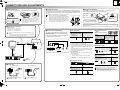
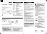
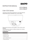
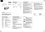
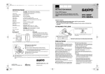
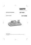
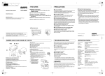
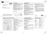
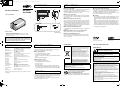
L5CP2_XE_US(VCC-6695P_6584DN)(ENGLISH).fm 1 ページ 2008年5月15日 木曜日 午前11時38分
English
Français
DIMENSIONS
PRECAUTIONS
<VCC-6695P>
INSTRUCTION MANUAL
VCC-6695P
VCC-6584DN
108 (4.3)
1.3
(0.05)
56 (2.2)
99 (3.9)
45
(1.8)
Color CCD Camera
1/4"-20 UNC
■ Protect from high temperatures
Do not use the unit if smoke or a strange odor comes from the unit,
or if it seems not to function correctly. Turn off the power
immediately and disconnect the power cord, and then consult your
dealer or an Authorized Sanyo Service Center.
Do not install close to stoves, or other heat sources, such as
spotlights, etc., or where it could be subject to direct sunlight, as this
could cause deformation, discoloration or other damages.
Be careful when installing close to the ceiling, in a kitchen or boiler
room, as the temperature may rise to high levels.
■ Do not open or modify
11 (0.4)
16
(0.6)
■ In case of a problem
28 (1.1)
Do not open the cabinet, as it may be dangerous and cause damage
to the unit. For repairs, consult your dealer or an Authorized Sanyo
Service Center.
■ Do not put objects inside the unit
25 (1.0)
Make sure that no metal objects or flammable substance get inside
the unit. If used with a foreign object inside, it could cause a fire, a
short-circuit or damage. Be careful to protect the unit from rain, sea
water, etc. If water or liquid gets inside the unit, turn off the power
immediately and disconnect the power cord, and then consult your
dealer or an Authorized Sanyo Service Center.
<VCC-6584DN>
11 (0.4)
16
(0.6)
1/4”–20 UNC
■ Be careful when handling the unit
28 (1.1)
26 (1.0)
■ Cleaning
• Dirt can be removed from the cabinet by wiping it with a soft cloth.
To remove stains, wipe with a soft cloth moistened with a soft
detergent solution and wrung dry, then dry by wiping with a soft
cloth.
• Do not use benzine, thinner or other chemical products on the
cabinet, as this may cause deformation and paint peeling. Before
using a chemical cloth, make sure to read all accompanying
instructions. Make sure that no plastic or rubber material comes
into contact with the cabinet for a long period of time, as this may
cause damage or paint peeling.
To prevent damage, do not drop the unit or subject it to strong shock
or vibration.
■ Do not install this unit close to magnetic fields
The magnetic fields may result in unstable operation.
About this manual
Unit: mm (inch)
• Before installing and using the camera, please read this manual carefully.
Be sure to keep it handy for later reference.
• This manual covers two models. Any difference between the two models is
indicated when necessary.
To prevent damage, do not install the unit where there is greasy
smoke or steam, where the humidity may get too high, or where
there is a lot of dust.
Depending on the conditions of use, installation and environment,
please be sure to make the appropriate settings and adjustments.
If you need help with installation and/or settings, please consult
your dealer or an Authorized Sanyo Service Center.
1AC6P1P3335-L5CP2/XE, US (0508KP-HS)
SPECIFICATIONS
Scanning system
: VCC-6695P: PAL standard 625 lines, 50 fields/sec.
VCC-6584DN: NTSC standard 525 lines, 60 fields/sec.
Image sensor
: 1/3" interline transfer method CCD
Number of effective pixels : VCC-6695P: 752 (H) x 582 (V)
VCC-6584DN: 768 (H) x 494 (V)
Horizontal resolution
: 540 TV lines, typical
Minimum illumination
(approx.)
: 0.25 lx (F1.2, B/W mode), 0.35 lx (F1.2, color mode)
Video output
: 1.0 V(p-p)/75 Ω, composite, BNC
Video S/N ratio
: More than 48 dB (AGC off: More than 50 dB)
Backlight compensation
: OFF, Multi-spot metering (High/Normal), Center zone
metering
White balance
: ATW/Manual
Light control
: Optical auto iris lens/Electronic iris (indoor use)
Lens mount
: CS mount
Flange back
: 12.5 mm ±0.5 mm/0.5 in. ±0.02 in. adjustment
Sync system
: Internal sync/Line lock
Day/Night mode
: ON/OFF
Operating Environment
: Temperature: -10°C – +50°C (14°F – 122°F)
Humidity: less than 90 % RH (no condensation)
Power supply
: VCC-6695P: 24 V AC ±10%, 50 Hz/ 12 – 15 V DC
VCC-6584DN: 24 V AC ±10%, 60 Hz/ 12 – 15 V DC
Power consumption
(approx.)
: 3.6 W (with auto-iris lens)
Weight (approx.)
: 260 g/9.2 oz. (without lens)
Appearance and specifications are subject to change without prior notice
or obligations.
■ Protect from humidity and dust
TROUBLESHOOTING
Before sending the camera out for repair, check the items below.
If the problem persists after checking these items, consult your
dealer or an Authorized Sanyo Service Center.
■ If no image appears
• Is the coaxial cable attached securely?
• Are the power and voltage normal?
• Has the iris of the lens been adjusted correctly (with the LEVEL
dial)?
• Is there adequate illumination?
■ If the image is unclear
•
•
•
•
Is the monitor adjusted correctly?
Is the flange-back position correctly set?
Is the lens in focus?
Is the lens clean?
Dirt or fingerprints on the lens can adversely affect the image.
Gently wipe any dirt or fingerprints off the lens with a soft cloth or
lens cleaning paper and cleaning fluid (commercially available).
For EU Users
The camera is a precision instrument. Handle it carefully and always
follow the safety precautions. If the camera requires service, never
try to repair it yourself or open the casing.
For servicing, maintenance, or repairs, consult your dealer or an
Authorized Sanyo Service Center.
Printed in China
For US and Canadian Users
Please note:
Your SANYO product is designed and manufactured
with high quality materials and components which
can be recycled and reused.
This symbol means that electrical and electronic
equipment, at their end-of-life, should be disposed
of separately from your household waste.
Please dispose of this equipment at your local
community waste collection/recycling centre.
In the European Union there are separate collection
systems for used electrical and electronic products.
Please help us to conserve the environment we live
in!
This symbol mark and recycle system are
applied only to EU countries and not applied
to countries in other areas of the world.
SANYO FISHER Sales (Europe) GmbH
Stahlgruberring 4, D-81829 München, Germany
SANYO Electric Co., Ltd.
1-1, Sanyo-cho, Daito City, Osaka 574-8534, Japan
For Russian Users
SERVICE
SANYO Electric Co., Ltd.
This product certified by official certification company
which is authorized by Russian Federation.
ДЛЯ ПОЛЬЗОВАТЕЛЕЙ РОССИЯ
Данная продукция сертифицирована официальным
органом по сертификации Российской Федерации.
Safety Guard
THIS SYMBOL INDICATES THAT THERE ARE IMPORTANT
OPERATING AND MAINTENANCE INSTRUCTIONS IN THE
LITERATURE ACCOMPANYING THIS UNIT.
WARNING:
TO PREVENT THE RISK OF FIRE OR ELECTRIC SHOCK, DO NOT
EXPOSE THIS APPLIANCE TO RAIN OR MOISTURE.
For the customers in Canada
This Class B digital apparatus complies with Canadian ICES-003.
Pour la clientèle canadienne
Cet appareil numerique de la Classe B est conforme à la norme
NMB-003 du Canada.
This installation should be made by a qualified service person and should
conform to all local codes.
This equipment has been tested and found to comply with the limits for a Class B
digital device, pursuant to Part 15 of the FCC Rules.
These limits are designed to provide reasonable protection against harmful
interference in a residential installation. This equipment generates, uses, and can
radiate radio frequency energy and, if not installed and used in accordance with the
instructions, may cause harmful interference to radio communications.
However, there is no guarantee that interference will not occur in a particular
installation. If this equipment does cause harmful interference to radio or television
reception, which can be determined by turning the equipment off and on, the user
is encouraged to try to correct the interference by one or more of the following
measures:
– Reorient or relocate the receiving antenna.
– Increase the separation between the equipment and receiver.
– Connect the equipment into an outlet on a circuit different from that to which the
receiver is connected.
– Consult the dealer or an experienced radio/TV technician for help.
This device complies with Part 15 of the FCC Rules. Operation is subject to the
following two conditions: (1) This device may not cause harmful interference, and
(2) this device must accept any interference received, including interference that
may cause undesired operation.
Changes or modifications not expressly approved by Sanyo may void the user's
authority to operate this camera.
L5CP2_XE_US(VCC-6695P_6584DN)(ENGLISH).fm 2 ページ 2008年5月15日 木曜日 午前11時38分
Français
English
CONNECTIONS AND ADJUSTMENTS
b Attaching the lens
b Camera attachment
b Flange-back adjustment
Use any DC type and CS mount lens equipped with an auto iris (sold separately).
When attaching the camera, make sure to verify that the attachment surface will allow full
tightening of the screws. Plaster board, etc., may not give a strong enough attachment, and
it is recommended to use a reinforcement, or other method so that the screws are anchored
securely.
This normally does not need adjustment. If the picture is out of focus at the telephoto
position, adjust the flange-back position as described below.
1
3
2
5 mm/0.2 in. max.
Pin layout for LENS terminal
Brake coil (–)
Drive coil (+)
Brake coil (+)
Drive coil (–)
• Depending on the type of the lens, the shape of
the lens plug may differ. In this case, consult your
dealer or an Authorized Sanyo Service Center.
• Apply adapter ring (sold separately) when you use
any C mount lens.
B Camera screws (shorter)
Loosen.
Tighten.
3
A
2
• You can change the bracket topside down. Make sure to
use the longer screws A to secure the bracket.
B
A Bracket screws (longer)
b Supported coaxial cables
1
4
LOCK
• When monitoring lighting or other extremely bright objects
(which exceed the maximum required illumination),
smearing may occur in the vertical or horizontal direction
(either above and below the high-brightness object or as a
perpendicular band). In such a case, adjust the angle of
illumination and other factors while observing the monitor.
Set to the maximum
wide-angle position
and focus the
picture.
Set to the maximum telephoto
position and focus the picture.
Repeat steps 2 and 3 until the image stays in-focus when changing from a wide-angle position to
a telephoto position.
Cable type – Length:
• RG-59U (3C-2V) – 250 m/273 yd max.
• RG-6U (5C-2V) – 500 m/547 yd max.
• RG-11U (7C-2V) – 600 m/656 yd max.
1 Iris setting (EI/AI)
b Camera adjustments/settings
The camera comes pre-adjusted and ready to install at the
time of factory shipment, but you can make adjustments or
settings if you need.
• When using an RG-59U (3C-2V) cable, do not use it on piping or air
wiring.
• If you use a cable other than the type above, the image or sync signal will
be attenuated and will not be transmitted correctly.
If you have trouble adjusting the camera, consult your dealer
or an Authorized Sanyo Service Center.
3 Backlight compensation
EI (Electronic Iris)
When using a manual or fixed
iris lens and the electronic iris
function is on
• For indoor use
AI (Auto Iris)
When using an auto-iris lens
L
1
H
3
NOTE on EI setting:
POWER
• Set the lens aperture to the shortest F stop.
BLC
D/N
ON CENT
LL
EI MULTI MANU
AI
INT
OFF OFF ATW
L
R WB B
PHASE
LEVEL
H
• If fluorescent lighting is used where the camera is installed, the
object will flicker as a result. This type of phenomenon can be
avoided by replacing the fluorescent lighting with incandescent
lamps.
• If the light entering the lens exceeds the maximum required
illumination, the image cannot be displayed properly. In that
case, manually adjust the lens iris.
NOTE on AI setting:
Normal
• L (Counterclockwise):
Closes the lens iris, making the entire image darker.
• H (Clockwise):
Opens the lens iris, making the entire image brighter.
: VIDEO IN
: VIDEO OUT
2 Day/Night function (D/N)
B/W
b Power cable
Color
Switchover point
<DC 12 V connection>
GND AC24V
GND AC24V
DC12V
DC12V
ON
Automatically switches to
B/W (non-IR sensitive) to
optimize low light surveillance
2
Check that polarity is correct.
4
OFF
3
4
3
OFF
Color images only
2
3
4
4
* If the background of the object is extremely dark, set to Center zone
metering.
4 White balance (WB)
MANU
(Manual white balance)
ATW
(Auto-Tracing
White balance)
Turn clockwise to
augment the color.
5
If the entire image is too dark or too bright, adjust the contrast
using the LEVEL dial.
To prevent a fire hazard use any UL
listed wire rated VW-1.
CENT
(Center zone metering)
Backlight compensation
to the central portion of
the screen
LEVEL
VIDEO OUT
<AC 24 V connection>
MULTI
(Multi-spot metering)
Backlight compensation
to the entire screen*
High
1
Monitor
Digital video recorder
(BLC)
Only when using an auto-iris lens
5
R WB B
5 Sync setting (LL/INT)
LL (Line-Lock)
(Only when using an AC power supply)
Synchronizes the unit with power
frequency*
6
PHASE
INT
(Internal sync)
6
* Adjust the roll by turning the PHASE dial on the second and subsequent
cameras.
If the vertical roll cannot be corrected by adjusting the
PHASE dial on the second and subsequent cameras, try
adjusting the PHASE dial on the first camera. If it still cannot
be corrected, please check that the polarity of the power
cords of all connected devices is correct.