
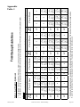
1
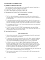
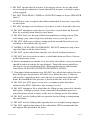
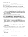
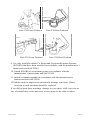
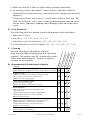
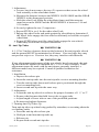
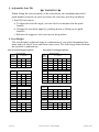
and
Patent Pending
Patent Pending
Owner’s Operation
and Maintenance Manual
DEALER: THIS MANUAL MUST BE GIVEN TO THE USER OF THE WHEELCHAIR
USER: BEFORE USING THIS WHEELCHAIR, READ THIS ENTIRE
MANUAL AND SAVE FOR FUTURE REFERENCE
For more information regarding PDG products,
parts and services please visit www.PDGmobility.com
M O B I L I T Y T E C H N O L O G I E S
Class 1 Medical Device
Registration CA 004986
May 2007
Fuze Part # 4532 - Patent Pending
Page
TABLE OF CONTENTS
1. NOTICE:
READ BEFORE USING................... p. 3
A. Warnings.............................................p. 3
B. Special Notes......................................p. 3
C. Unpacking...........................................p. 3
D. Out of the Box
Assembly Instructions........................p. 6
E. Inspection............................................p. 6
F. Storage.................................................p. 6
G. Contacting A Qualified
Service Agent To Obtain Service.......p. 6
H. Specifications......................................p. 7
2.0 GENERAL GUIDELINES.............. p. 8
2.1 INDICATIONS FOR USE.................p. 8
2.2 CONTRAINDICATIONS
FOR USE.......................................... p. 8
A. Information for Health Care
Professionals or Assistants . ..............p. 8
B. Operating Information........................p. 8
C. Weight Training................................p. 10
D. Weight Limitation.............................p. 10
E. Stability and Balance........................p. 10
3.0 TROUBLESHOOTING................ p. 16
4.0 MAINTENANCE........................... p. 13
A. Maintenance Safety Precautions.......p. 16
B. Tools Required..................................p. 17
C. Cleaning............................................p. 17
D. Recommended Maintenance
Schedule...........................................p. 17
5.0 SET-UP AND ADJUSTMENT...... p. 18
A. Footrests - Swing-away
(70° and 90°)....................................p. 18
B. Locking Flip-up Arms.......................p. 19
C. T-Style Arms.....................................p. 20
D. Back Angle.......................................p. 20
E. Adjustable Angle
Stroller Handle.................................p. 22
F. Quick Release Axles..........................p. 23
G. Wheel Locks - Front or Rear............p. 24
H. Anti-Tip Tubes..................................p. 25
I. Adjustable Seat Tilt............................p. 26
J. Seat Height.........................................p. 26
K. Seat Depth........................................p. 27
L. Seat Width.........................................p. 28
F. Safety and Handling
of Wheelchairs.................................p. 10
6.0 SETUP GUIDELINES................... p. 28
G. Note To Wheelchair Assistants.........p. 11
7.0 TESTING........................................ p. 28
H. Tilting the Wheelchair......................p. 11
8.0 LIMITED WARRANTY............... p. 28
I. Curbs and Steps..................................p. 11
Appendix
J. Stairs..................................................p. 12
Table 1 - Seat Height Adjustments........p. 29
K. Transferring To
and From Other Seats.......................p. 13
Table 2 ..................................................p. 30
L. Reaching, Leaning
and Bending Forwards.....................p. 13
Table 3 - Seat Pan Sizes.........................p. 31
Table 4 - Seat Pan Size Options............p. 31
Table 5 - Seat Pan Size Overlap............p. 32
M. Reaching and
Leaning Backwards..........................p. 13
Table 6 - Adjustments............................p. 33
N. Motor Vehicle Use............................p. 14
Table 7 - Fuze T50 Set-up Guide..........p. 34
Page 2
Page
Fuze Part # 4532 - Patent Pending May 2007
1. NOTICE: READ BEFORE USING
A. Warnings
Warning/Caution notices as used in this manual apply to hazards or unsafe
practices, which could result in personal injury or property damage.
1. DO NOT OPERATE THIS EQUIPMENT WITHOUT FIRST READING
AND UNDERSTANDING THIS MANUAL.
2. IF YOU ARE UNABLE TO UNDERSTAND THE WARNINGS,
CAUTIONS AND INSTRUCTIONS, CONTACT A HEALTH CARE
PROFESSIONAL, DEALER OR A QUALIFIED TECHNICIAN
BEFORE ATTEMPTING TO USE THIS EQUIPMENT - OTHERWISE
INJURY OR DAMAGE MAY RESULT.
3. THE INITIAL SET UP OF THIS WHEELCHAIR MUST BE
PERFORMED BY A QUALIFIED TECHNICIAN. PROCEDURES
OTHER THAN THOSE DESCRIBED IN THIS MANUAL MUST BE
PERFORMED BY A QUALIFIED TECHNICIAN.
B. Special Notes
1. The information contained in this document is subject to change without
notice. As a manufacturer of wheelchairs, PDG endeavors to supply a wide
variety of wheelchairs to meet many needs of the end user. However, final
selection of the type of wheelchair to be used by an individual rests solely
with the user and his/her health care professional capable of making such a
selection.
2. Tie-down restraints and seat positioning straps. PDG recommends that
wheelchair users NOT be transported in vehicles of any kind while in
wheelchairs unless equipped with a manufacturer installed transport kit.
3. Restraints – seat & chest positioning straps. It is the obligation of the DME
dealer, therapists and other health care professionals to determine if a
seat/chest positioning strap is required to ensure the safe operation of this
equipment by the user. Serious injury can occur in the event of a fall from
a wheelchair.
C. Unpacking
1. Check for any obvious damage to the carton or its contents. If damage is
evident, notify your Dealer/Carrier immediately.
2. Remove all loose packing from the carton.
3. Carefully remove all components from the carton.
Note: Unless the PDG wheelchair is to be assembled immediately, retain
cartons and packing materials for use in storing the wheelchair until
assembly is required.
May 2007
Fuze Part # 4532 - Patent Pending
Pending
Page 3
1. Seat Pan
6. Arm Rest Release Trigger
11. Front Casters
2. Arm Rest
7. Gas Strut
12. Lower Frame
3. Push Handle
8. Cross Bar
13. Front Pivot Bracket
4. Foot Rest
9. Caster Cap
14. Axle Plate
5. Tilt Trigger
10. Caster Journal
15. Anti-Tip System
16. Rear Wheel
3
5
2
1
6
4
7
8
13
9
10
12
14
15
11
Page 4
Page
Fuze Part # 4532 - Patent Pending May 2007
1. Seat Pan
7. Tilt Locking System
12. Lower Frame
2. Arm Rest
8. Cross Bar
13. Pivot Point Arm
3. Push Handle
9. Caster Cap
14. Axle Plate
4. Foot Rest
10. Caster Journal
15. Anti-tip System
5. Tilt Trigger
11. Front Casters
16. Rear Wheel
17. Wheel Lock
6. Arm Rest Release Trigger
3
2
5
1
16
13
4
7
6
8
9
10
14
12
15
17
11
May 2007
Fuze Part # 4532 - Patent Pending
Pending
Page 5
D. Out of the Box Assembly Instructions
When unpacking a new Fuze wheelchair, you will need to assemble the
armrests (T-style version only) and front rigging to complete the setup.
1. Install the T-style arm assemblies by inserting the metal locking
tab into the arm receivers on the chair (see Section 5-D for detailed
instructions).
2. Install the swing-away front rigging by inserting the front rigging
assembly at 90º to the chair, into the front rigging mount and swiveling
the front rigging forward to an in-line position with the wheelchair (see
Section 5-A for detailed instructions).
E. Inspection
1. Examine the exterior of the PDG wheelchair for nicks, dents, scratches,
or other damages. Inspect all components. If damage is evident, notify
your Dealer/Carrier immediately.
F. Storage
1. Store the repackaged PDG wheelchair in a dry area.
2. DO NOT place other objects on top of the repackaged wheelchair.
G. Contacting a Qualified Service Agent to Obtain Service
PDG has Qualified Service Agents in many locations. To find your nearest
Qualified Service Agent, visit our web site at www.pdgmobility.com and
click on CONTACTS. If you are uncertain as to which CONTACT is
most appropriate for your need, contact PDG directly by telephone, fax,
or e-mail to obtain the necessary information. You will be asked by the
Qualified Service Agent for the serial number that is affixed to the wheelchair. This information will allow PDG to serve you better.
In some circumstances, it may be necessary to return your wheelchair to a
Qualified Service Agent for repairs. If any of the following conditions are
observed, the wheelchair must be serviced by a Qualified Service Agent:
1. Any part of the frame is cracked or broken
2. Any weld is cracked or broken
Always contact your Service Agent prior to sending a wheelchair for
repairs. For safe and secure shipping, the wheelchair must be placed
in a suitable carton, or fastened to a pallet, to ensure it does not sustain
damage during shipping. The Qualified Service Agent will provide specific
instructions for packaging and shipping your wheelchair. Alternatively,
the Qualified Service Agent may arrange for pick-up.
Page 6
Page
Fuze Part # 4532 - Patent Pending May 2007
H. Specifications
Overall Width - seat width + 8”
Overall Depth - without front rigging - 35 ½ ”
Overall Height - 24” back height - 42”
Shipping Weight - 45 lbs
Anti-tippers - standard
Footrests - Swing-away footrests - standard
- Elevating leg rests - optional
Back Angle Adjustment - 90 degrees to 120 degrees
Rear Wheels - 12”, 16”, 20”, 22” or 24”
- Urethane or pneumatic
Casters - 6” or 8”
- Urethane or pneumatic
Seat Width - 15”, 16”, 17”, 18”, 19”, 20”
Seat Depth - 15”, 16”, 17”, 18”, 19”, 20”
1
Seat Height - 13”, 14”, 15”, 16”, 17”, 18”, 19”, 20”
Back Height - 20” or 24”
Wheel Locks - Push to lock
Tilt-in-Space - Fuze T50 - 50 degrees of tilt
- Fuze T20 - 20 degrees of tilt
Weight Limitation - 250 pounds
1
The seat-to-floor heights are based on urethane tires. These heights can vary ¼ inch due to tire wear.
I. Additional Information
Additional information is available upon request. Please contact PDG at
[email protected] .
May 2007
Fuze Part # 4532 - Patent Pending
Pending
Page 7
2.0 GENERAL GUIDELINES
2.1 INDICATIONS FOR USE
The intended use of this wheelchair is as a manually operated, attendant or
user propelled, manual mechanical wheelchair.
2.2 CONTRAINDICATIONS FOR USE
A. Information for Health Care Professionals or Assistants
æWARNINGæ
1. The Fuze wheelchair must be operated by a health care professional or
assistant when in ANY tilt position only when client is unable to propel in
a tilted position.
2. To maintain maximum stability, position the rear wheels in the most rearward position in the axle mounting plate. Moving the rear wheels to any of
the other mounting positions causes the wheelchair to decrease in stability.
3. If moving the rear wheels to ANY forward position, ensure the wheelchair
is stable BEFORE using.
4. ALWAYS ensure stability BEFORE using maximum amount of tilt-inspace or moving the rear wheels forward. TEST wheelchair BEFORE it is
occupied by the end user to ensure safety.
B. Operating Information
æWARNINGæ
1. Unless otherwise noted, all service and adjustments should be performed
while the wheelchair is unoccupied.
2. To determine and establish your particular safety limits, practice bending,
reaching and transferring activities in the presence of a qualified health
care professional BEFORE attempting active use of the wheelchair.
3. ALWAYS wear your SEAT/CHEST POSITIONING STRAP when applicable. Inasmuch as the SEAT/CHEST POSITIONING STRAP is an
option on this wheelchair (you may order with or without the Seat /Chest
Positioning Strap), PDG strongly recommends ordering the Seat/Chest
Positioning Strap as an additional safeguard for the wheelchair user.
4. ALWAYS check foam grips for looseness BEFORE using the wheelchair. If
loose, contact a qualified technician for instructions.
5. The necessary back angle MUST be selected BEFORE repositioning the
rear wheels forward.
Page8
Page
Fuze Part # 4532 - Patent Pending May 2007
6. DO NOT operate the tilt-in-space if the trigger release levers and cables
are not properly adjusted to ensure that the tilt-in-space is locked in place
when engaged.
7. DO NOT TRAVERSE, CLIMB or GO DOWN ramps or slopes GREATER
than 9°.
8. NEVER leave the occupied wheelchair unattended at any time, especially
on an incline.
9. DO NOT attempt to reach objects if you have to move forward in the seat.
10. DO NOT attempt to reach objects if you have to pick them up from the
floor by reaching down between your knees.
11. DO NOT lean over the top of the back upholstery/seating system. This
will change your center of gravity and may cause you to tip over.
12. DO NOT shift your weight or sitting position toward direction you are
reaching as wheelchair may tip over.
13. WHEEL LOCKS ARE NOT BRAKES. DO NOT attempt to stop a moving wheelchair with the wheel locks.
14. DO NOT tip the wheelchair onto the rear wheels without assistance.
15. DO NOT use an escalator to move a wheelchair between floors. Serious
bodily injury may occur.
16. Before attempting to transfer in or out of the wheelchair, every precaution
should be taken to reduce the gap distance. Turn both casters parallel to
the object you are transferring onto. When transferring to and from the
wheelchair, ALWAYS ENGAGE BOTH WHEEL LOCKS.
17. If equipped with pneumatic tires DO NOT use wheelchair unless the tires
have the proper tire pressure. DO NOT over inflate the tires. Failure to
follow these suggestions may cause the tire to explode and cause bodily
harm. Recommended tire pressure is listed on the side wall of the tire.
18. DO NOT use ANY parts, accessories, or adapters other than those
authorized by PDG. Otherwise, the warranty is void.
19. DO NOT attempt to lift a wheelchair by lifting on any removable (detachable) parts. Lifting by means of any removable (detachable) parts of a
wheelchair may result in injury to the user or damage to the wheelchair.
20. DO NOT use the folding links or spreader bar for lifting or transporting
the wheelchair.
21. DO NOT use the folding links spreader bar as a weight bearing support.
22. DO NOT stand on the frame of the wheelchair. PDG recommends that
anti-tippers BE attached at all times.
May 2007
Fuze Part # 4532 - Patent Pending
Pending
Page 9
23. DO NOT use the footplates as a platform. When getting in or out of the
wheelchair, make sure that the footplates are in the upward position.
C. Weight Training
æWARNINGæ
PDG DOES NOT recommend the use of its wheelchairs as a weight training
apparatus. PDG wheelchairs have NOT been designed or tested as a seat for
any kind of weight training. If occupant uses said wheelchair as a weight
training apparatus, PDG shall NOT be liable for bodily injury and the warranty is void.
D. Weight Limitation
æWARNINGæ
The Fuze wheelchair has a weight limitation of 250 lbs
E. Stability and Balance
æWARNINGæ
1. Anti-tippers MUST be attached at all times.
2. To assure stability and proper operation of your wheelchair, you must at
all times maintain proper balance. Your wheelchair has been designed to
remain upright and stable during normal daily activities as long as you do
not move beyond the center of gravity.
3. Virtually all activities which involve movement in the wheelchair have an
effect on the center of gravity. PDG recommends using seat/chest positioning straps for additional safety while involved in activities that shift your
weight.
4. DO NOT lean forward out of the wheelchair any further than the length
of the armrests. Make sure the casters are pointing in the forward position whenever you lean forward. This can be achieved by advancing the
wheelchair and then reversing it in a straight line.
5. The PDG Fuze wheelchair should be operated by an assistant when the
wheelchair is in any tilted position.
F. Safety and Handling of Wheelchairs
Safety and handling of the wheelchair requires the close attention of the
wheelchair user as well as the assistant. This manual points out the most
common procedures and techniques involved in the safe operation and maintenance of the wheelchair. It is important to practice and master these safe
techniques until you are comfortable in maneuvering around the frequently
encountered architectural barriers.
Page10
Page
Fuze Part # 4532 - Patent Pending May 2007
Use this information only as a basic guide. The techniques that are discussed
on the following pages have been used successfully by many.
Individual wheelchair users often develop skills to deal with daily living
activities that may differ from those described in this manual. PDG recognizes and encourages each individual to try what works best for him/her in
overcoming architectural obstacles that they may encounter, however ALL
WARNINGS and CAUTIONS given in this manual MUST be followed.
Techniques in this manual are a starting point for the new wheelchair user
and assistant with “safety” as the most important consideration for all.
G. Note to Wheelchair Assistants
æWARNINGæ
1. When assistance to the wheelchair user is required, remember to use good
body mechanics. Keep your back straight and bend your knees whenever
tipping the wheelchair or traversing curbs, or other impediments.
2. DO NOT attempt to lift the wheelchair by any removable (detachable)
parts. Lifting by means of any removable (detachable) parts of a wheelchair may result in injury to the user or damage to the wheelchair.
3. DO NOT use the spreader bar for lifting or transporting the wheelchair.
4. DO NOT use the spreader bar as a weight bearing support. When learning
a new assistance technique, have an experienced assistant help you before
attempting it alone.
H. Tilting the Wheelchair
æWARNINGæ
1. DO NOT tilt the wheelchair without assistance
2. When tilting the wheelchair, an assistant should grasp the back of the
wheelchair on a non-removable (non-detachable) part. Inform the wheelchair occupant before tilting the wheelchair and remind him/her to lean
back. Be sure the occupant’s feet and hands are clear of all wheels.
3. After mastering the techniques of tilting the wheelchair, use this procedure
to tackle shallow curbs, short stairs, etc.
I. Curbs and Steps
æWARNINGæ
1. Each person who helps you should read the “Notes to Wheelchair
Assistants” (Section G above).
May 2007
Fuze Part # 4532 - Patent Pending
Pending
Page 11
2. Wheelchairs with Step Tubes
a. Apply a continuous downward motion until the balance point is achieved
and the front casters clear the curb. At this point, the assistant will feel a
difference in the weight distribution.
b. Roll the wheelchair forward and slowly lower the wheelchair in one
continuous movement. Do not let the wheelchair drop the last few inches
to the ground. This could result in injury to the occupant. Push the
wheelchair forward until the rear wheels roll up and over the curb.
3. Wheelchairs Without Step Tubes
a. Unless the first assistant has exceptional upper body strength, it is recommended that METHOD 2 use two (2) assistants. The second assistant
should be positioned at the front of the wheelchair lifting upward on a
non-removable (non-detachable) part of the wheelchair frame when lifting the wheelchair and stabilizing the wheelchair when the wheelchair is
being lowered to the ground.
b. The first assistant should stand on the sidewalk and turn the wheelchair
so that the rear wheels are against the curb. The wheelchair should
be tilted back to the balance point and, in one continuous downward
movement, the rear wheels should be pulled up and over the curb. DO
NOT return the front casters to the ground until the wheelchair has been
pulled backward far enough for the front casters to clear the edge of the
curb.
J. Stairs
æWARNINGæ
1. Extreme caution is advised when it is necessary to move an occupied
wheelchair up or down the stairs. PDG recommends using two (2) assistants and making thorough preparations. Make sure to use ONLY secure,
non-detachable parts for hand-held supports. Lifting by means of any
removable (detachable) parts of a wheelchair may result in injury to the
user or damage to the wheelchair.
2. After the wheelchair has been tilted back to the balance point, one assistant
(in the rear) backs the wheelchair up against the first step, while securely
grasping a non-removable (non-detachable) part of the wheelchair for
leverage.
3. The second assistant, with a firm hold on a non-detachable part of the
framework, lifts the wheelchair up and over the stair and steadies the
wheelchair as the first assistant places one (1) foot on the next stair and
repeats STEP 2.
4. The wheelchair should be kept tilted on its back wheels until the last stair
has been negotiated and the wheelchair has been rolled away from the
stairway.
Page12
Page
Fuze Part # 4532 - Patent Pending May 2007
K. Transferring To and From Other Seats
æWARNINGæ
1. BEFORE attempting to transfer in or out of the wheelchair, every precaution should be taken to reduce gap distance. Turn both casters toward
the object you are transferring onto. Also be certain the wheel locks are
engaged to help prevent wheels from moving.
2. CAUTION: When transferring, position yourself as far back as possible in
the seat. This will prevent the possibility of the wheelchair tipping forward.
3. NOTE: This activity may be performed independently provided you have
adequate mobility and upper body strength.
4. Position the wheelchair as close as possible along side the seat to which
you are transferring, with the front casters pointing toward it. Engage
wheel locks. Shift body weight into seat with transfer.
5. During independent transfer, little or no seat platform will be beneath you.
Use a transfer board if at all possible.
L. Reaching, Leaning and Bending - Forward
æWARNINGæ
1. DO NOT attempt to reach objects if you have to move forward in the seat
or pick them up from the floor by reaching down between your knees.
2. Many activities require the wheelchair owner to reach, bend and transfer
in and out of the wheelchair. These movements will cause a change to
the normal balance, the center of gravity, and the weight distribution of
the wheelchair. To determine and establish your particular safety limits,
practice bending, reaching and transferring activities in several combinations in the presence of a qualified health professional BEFORE attempting
active use of the wheelchair.
3. Proper positioning is essential for your safety. When reaching, leaning,
bending forward, it is important to use the front casters as a tool to
maintain stability and balance.
M. Reaching and Leaning - Backwards
æWARNINGæ
1. DO NOT lean over the top of the back upholstery. This will change your
center of gravity and may cause you to tip over.
2. Position wheelchair as close as possible to the desired object. Point front
casters forward to create the longest possible wheelbase. Reach back only
as far as your arm will extend without changing your sitting position.
May 2007
Fuze Part # 4532 - Patent Pending
Pending
Page 13
N. Motor Vehicle Use
æWARNINGæ
Identify whether your chair has been manufactured with the Transit TieDown System (TTDS).
If your chair is NOT equipped with the Transit Tie-Down System
(TTDS), this wheelchair DOES NOT meet federal standards for motor
vehicle seating.
1. NEVER let anyone sit in this chair while in a moving vehicle.
2. ALWAYS secure the rider with proper vehicle restraints. In an accident or
sudden stop the rider may be thrown from the chair. Wheelchair seatbelts
will not prevent this and further injury may result from the belts or straps.
3. NEVER transport this chair in the front seat of a vehicle. It may shift and
interfere with the driver.
4. ALWAYS secure this chair so that it cannot roll or shift.
5. Do not use any chair that has been involved in a motor vehicle accident.
If your chair is equipped with the Transit Tie-Down System (TTDS):
1. If possible and feasible, the rider should transfer to the Original Equipment
Manufacturer vehicle seat and use the vehicle restraint.
2. Use only Wheelchair Tie Down and Occupant Restraint Systems
(WTORS) which meet the requirements of SAE J2249 Recommended
Practice – Wheelchair Tie Down and Occupant Restraint Systems For Use
in Motor Vehicles. Do not use WTORS designed to rely on the wheelchair
structure to transfer occupant restraint loads to the vehicle.
3. The rider must not weigh more than 250 lbs.
4. The wheelchair has been dynamically tested in a forward –facing mode
for a 30 mph frontal impact test. The wheelchair must be forward facing
during transport.
5. In order to reduce the potential of injury to vehicle occupants, wheelchairmounted accessories, such as trays and respiratory equipment should be
removed and secured separately.
6. Postural supports and positioning devices should not be relied on for
occupant restraint.
7. Do not alter or substitute wheelchair frame parts, components or seating.
8. The figures below show the locations of the wheelchair securement points,
front and back.
Page14
Page
Fuze Part # 4532 - Patent Pending May 2007
Fuze T20 Front Tiedown
Fuze T50 Front Tiedown
Fuze T20 Rear Tiedown
Fuze T50 Rear Tiedown
9. Use only with Wheelchair Tie Down and Occupant Restraint Systems
(WTORS) that have been installed in accordance with the manufacturer’s
instructions and SAE J2249.
10. Attach WTORS to securement points in accordance with the
manufacturer’s instructions and SAE J2249.
11. Attach occupant restraints in accordance with the manufacturer’s
instructions and SAE J2249.
12.Sudden stops or impacts can structurally damage your chair. Chairs
involved in such incidents should be replaced.
If you fail to heed these warnings, damage to your chair, a fall, tip-overs or
loss of control may occur and cause severe injury to the rider or others.
May 2007
Fuze Part # 4532 - Patent Pending
Pending
Page 15
3. TROUBLESHOOTING
You will need to adjust your chair from time to time for best performance.
Use the chart provided below to troubleshoot and find a solution.
Symp
toms
Chair
Veers
to Ri
ght
Chair
Veers
to Le
Slugg
ft
ish
Perfo Turning o
rman
r
ce
Caste
rs Flu
tter
Squea
ks an
d Rat
tles
Loose
ness i
n Ch
air
Chair
Cont
a
ct
On 3
Whee s Only
ls
Note: Make only ONE change at a time.
Solutions
Check tire pressure.
Check for loose nuts and bolts.
Check caster angle.
Check that both casters
contact the ground. If not,
add proper spacers between
bottom surface of lower bearing
and top of fork stem nut. Check
on a flat surface.
4. MAINTENANCE
Every six (6) months take your wheelchair to a qualified technician for a
thorough inspection and servicing. Regular cleaning will reveal loose or
worn parts and enhance the smooth operation of your wheelchair. To operate
properly and safely, your wheelchair must be cared for just like any other
vehicle. Routine maintenance will extend the life and efficiency of your
wheelchair. Initial adjustments should be made to suit personal body structure
and preference. Thereafter, follow these maintenance procedures:
A. Maintenance Safety Precautions
æWARNINGæ
1. After ANY adjustments, repair or service and BEFORE use, make sure all
attaching hardware is tightened securely - otherwise injury or damage may
result.
2. DO NOT over tighten hardware attaching to the frame. This could cause
damage to the frame tubing.
3. If the tires are pneumatic, DO NOT use the wheelchair unless it has the
proper tire pressure. DO NOT over inflate the tires. Failure to follow
these suggestions may cause the tire to explode and cause bodily harm.
Recommended tire pressures will be listed on the sidewall of the tires.
4. Periodically adjust wheel locks in correlation to tire wear. Refer to the
WHEEL LOCKS SECTION of this manual.
Page 16
Page
Fuze Part # 4532 - Patent Pending May 2007
5. Make sure that ALL bolts are tight before operating wheelchair.
6. As with any vehicle, the wheels, casters and tires should be checked
periodically for cracks and wear, and any defective components should be
replaced.
7. Clean quick-release axles once (1) a week with a Teflon® lubricant. DO
NOT use WD-40®, 3-in-1 oil®, or other penetrating lubricants on quick
release axles. Otherwise, binding and/or damage to the wheelchair may
occur.
B. Tools Required
The following tools are needed to make adjustments to the wheelchair
1. Philips Screw Driver
2. Allen Keys: 1/8”, 5/32”, 3/16”, 7/32”, 1/4”
3. Adjustable or Open-End Wrenches: 3/8”, 7/16”, 1/2”, 9/16”, 3/4”
4. Socket Head Driver with Socket Heads: 3/8”, 7/16”, 1/2”, 9/16”, 3/4”, 1-1/6”
C. Cleaning
y
t / Ad
just W
eekly
t / Ad
just W
eekly
Inspe
ct / A
djust
Perio
dica
Inspe
c
Inspe
c
CHECK
GENERAL
Wheelchair rolls straight (No excessive drag or pull to one side).
Initia
ll
D. Recommended Maintenance Schedule
lly
Periodic cleaning of all surfaces will help
keep you wheelchair looking good and operating
properly. All surfaces may be cleaned with warm
water and a mild detergent. Do not use abrasive
cleaners on any surfaces.
WHEEL LOCKS
Make sure they are not interfering with tires rolling.
Pivot points are free of wear and looseness.
Wheel locks are easily engaged.
SEAT / BACK UPHOLSTERY
Inspect for rips and sagging.
Inspect fastenings to ensure they are secure.
REAR WHEELS
No excessive side movement or binding when
lifted and spun.
Quick-relaese axles lock properly (if applicable).
Inspect wheels and tires for cracks and wear.
Replace when necessary.
FRONT CASTER
Inspect wheelfork assembly. Caster should spin freely.
Wheel bearings are clean and free of moisture.
Inspect wheels and tires for cracks and wear.
Replace when necessary.
CLEANING
Clean upholstery and armrests
May 2007
Fuze Part # 4532 - Patent Pending
Pending
Page 17
5. SET-UP AND ADJUSTMENT
æWARNINGæ
After ANY adjustments, repair or service and BEFORE use, make sure all
attachment hardware is tightened securely; otherwise, injury or damage may
result.
A. Footrests – Swing-away (70° and 90°)
1. Installation
a. Turn the footrest to the side (open footplate is perpendicular to
wheelchair).
b. Insert footrest mounting pin into mounting tube.
c. Rotate the footrest towards the inside of the wheelchair until it locks into
place. The footplate will be on the inside of the wheelchair when locked
in place.
d. Repeat this procedure for other footrest assembly.
2. Removal
a. To release the footrest, push the footrest release lever.
b. Rotate footrest outward and lift.
3. Adjusting
NOTE: Release the footrest locking mechanism and lift the footrest
mounting pins out of its mounting tube.
NOTE: Make sure to note the position of the washers before disassembly.
a. Remove impact guards and/or calf strap, if so equipped. Remove the
hex screw and coved washer and position the footrest assembly to a
determined height.
b. Line up the mounting hole in the footrest frame, reinsert the hex screw
and coved washer; hand-tighten.
c. Securely tighten the hex screw and coved washer.
d. Repeat this procedure for the other footrest.
e. Replace impact guards and/or calf strap, if so equipped.
Page18
Page
Fuze Part # 4532 - Patent Pending May 2007
B. Locking Flip-up Arms
1) Use
a. Pull actuator D shown in
Figure 1 towards the front of the
wheelchair.
b. While holding the actuator of the
locking mechanism, lift up on the
cantilever arm.
NOTE: If necessary, the locking
mechanism in the cantilever arm
can be repositioned so the cantilever
arm will open down instead of up.
For this adjustment, contact a
qualified technician.
Figure 1
c. To lock the cantilever arm in the down position, push down until there is
an audible click.
d. Pull up on the cantilever arm to make sure it is locked in place.
2) Installation
NOTE: When removing the locknuts and washers from the cantilever
arm assembly, leave the top hex bolt, coved washers and spacer (between
adjustment plate and cantilever arm) in place.
a. Place the partially assembled cantilever arm assembly with mounting
hardware against the back cane at the desired height. Make sure the
adjustment plate is on the outside of the wheelchair.
b. Insert the bottom bolt (with coved washer) through the adjustment plate
and back cane.
c. Securely tighten the cantilever arm to the wheelchair with two locknuts
and washers (B in figure 2).
d. Adjust the angle of the cantilever arm, if necessary. Refer to Step 3
below in this section of the manual.
3) Adjustment
e. Arm Angle Adjustment
NOTE: This adjustment is recommended if the back angle has been
changed.
i. Flip the cantilever arm up and out of the way.
ii. Remove the locknut that secures the locking pin to the arm adjustment plate (C in figure 2).
May 2007
Fuze Part # 4532 - Patent Pending
Pending
Page 19
iii. Install pin in the mounting hole in the armrest mount plate that gives
the desired angle adjustment plate that will be used to correspond to
the back angle.
NOTE: Arm angles are displayed in figure 2 for a back at 90°, they vary by
6°, also the pins cannot occupy adjacent holes (i.e. both 90° and 96°).
iv. Securely tighten the locking pin and washer to the adjustment plate
with a locknut.
v. Repeat STEPS I to iv for the other arm, if necessary.
4) Height Adjustment
a. Remove fasteners securing the cantilever arm assembly to the back cane
(item B as shown in Figure 2).
b. Remove the cantilever arm assembly with hardware from the back cane.
c. Perform STEPS a. to d. in Installation section to reposition the arm at the
desired height.
5) Arm Depth Adjustment and Arm Pad Replacement
a. Remove the mounting screws from the armrest pad (A in Figure 2).
b. Replace with NEW armrest pad and/or adjust to desired length.
i. Desk Length Arms - to one of three positions depending on the desired
arm pad depth.
ii. Full Length Arms - to one of five positions depending on the desired
arm pad depth.
c. Secure with existing hardware.
C. T-Style Arms
Installation
a. Attach the T-style arm rest receiver
using the shoulder bolt (item B in
Figure 2) and the button-head cap
screw (item E in Figure 2).
NOTE: Make sure the locking lever is towards
the front of the wheelchair. Spacers must be
added on the far side of the shoulder bolt and
between the T-style arm rest receiver and the
seat rail for the hex bolt.
b. Slide the T-style arm into the socket until
the locking lever is in the slot in the
T-arm socket and an audible “click”
is heard.
Page 20
Page
Fuze Part # 4532 - Patent Pending Figure 2
May 2007
c. Pull up on the T-style arm to make sure it is locked in place.
d. Adjust the T-style arm for desired height, width and depth, if necessary.
Refer to Adjustment instructions in this section of the manual below.
e. Repeat STEPS 1-4 for opposite side of wheelchair.
Removal
a. Press up on the locking lever, indicated by C in figure 3, and lift the
T-style arm straight up and out of the socket.
b. Repeat for opposite side of the wheelchair.
Adjustment
a. Depth Adjustment
i. Remove the two screws that secure the arm pad to the arm tube (item
D in Figure 3).
ii. Turn the arm pad 180º around and reposition the arm pad on the arm
tube.
iii. Re-secure the arm pad to the arm tube with the same screws. Tighten
securely.
iv. Repeat for the opposite side, if necessary.
b. Height Adjustment
i. Depress button A, indicated in figure 3, then pull up or push down on
the T-style arm until desired height is reached.
ii. Release button A and continue pushing or pulling until and audible
“click” is heard and the arm is locked in place.
D. Back Angle
æWARNINGæ
The back MUST be locked securely in place BEFORE using the wheelchair.
C
1. Adjustment – Back Angle Locking Pin Locations
a. Locking pins in (items A in Figure 3)
can be repositioned to change the back
angle of the chair.
b. The available angles start at 84° in the
top hole and incremented by 6° for each
subsequent hole, as noted in Figure 3.
Figure 3
May 2007
Fuze Part # 4532 - Patent Pending
Pending
Page 21
c. Loosen and withdraw locking pin from back angle support plates.
d. Reposition to desired location and reinsert and tighten locking pin.
2. Selecting Between Back Angles
a. To adjust between the two locking pin (back angle) positions, lift the
actuator handles (item C in Figure 3) on each side of the seat back
upwards to release the latches from the pins.
b. Reposition the seat back to the desired angle and align the latches with
the desired pin location and release latches to engage.
c. Push and pull the back to make sure it is locked in position.
E. Adjustable Angle Stroller Handle
1. Installation
a. Remove end caps from both back canes.
b. Slide the adjustable height stroller
handle into the back canes.
c. Secure adjustable angle stroller handle
to the back canes with the two quick
release pins (C in Figure 4).
d. If necessary, adjust the height. Refer to
ADJUSTMENT in this section of the manual.
Figure 4
2. Removal
a. Remove the two quick release pins (item C in Figure 4) by pulling on the
rings.
b. Remove the adjustable angle stroller handle from the back cane.
c. Install end caps on the back canes.
3. Adjustment
a. Angle
i. Depress the 2 buttons labeled A in figure 4.
ii. Adjust stroller handle to desired angle.
iii. Release the buttons and push down on the stroller handle to ensure
release levers hold the desired position.
Page 22
Page
Fuze Part # 4532 - Patent Pending May 2007
b. Width
i. Undo the 4 fasteners (B in Figure 4)
ii. Insert one half of the stroller handle into a back cane, secure it with a
quick release pin (C in figure 5)
iii. Insert the other half of the stroller handle into the other back cane
(previously set to the desired width) and fasten it with a quick release
pin. Slide the connecting tube until it lines up with 2 sets of holes on
each half of the handle.
iv. Replace and tighten the fasteners and push on the handle to make
sure it’s secure.
F. Quick Release Axles (Optional)
æWARNINGæ
If any adjustments (size or position) to the rear wheels have been made, the
anti-tippers must be adjusted to maintain the 1-1/2 to 2-inch clearance. If this
adjustment cannot be made with the anti-tippers currently installed, a different model may be required. Consult a qualified technician for assistance.
æWARNINGæ
Make sure detent button and locking balls of the quick-release axles are fully
engaged BEFORE operating the wheelchair. The locking balls MUST be
protruding past the inside of the axle mounting plate for a positive lock. Keep
locking balls clean.
1. Installation
a. Push in the detent button of the quick-release axle and insert the quickrelease axle through the center bearings of the rear wheel.
b. Push in the button of the quick-release axle again and insert the axle
(with wheel) into the axle mounting plate on the side of the wheelchair
frame until the assembly locks in place.
c. If the locking balls of the quick-release axles are not protruding past
the inside of the axle mounting plate or there is too much movement
of the rear wheel assembly in a back and forth position, refer to
ADJUSTMENT section below.
d. Repeat STEPS a to c for other rear wheel assembly.
e. Adjust the wheel locks. Refer to WHEEL LOCKS SECTION of this
manual.
May 2007
Fuze Part # 4532 - Patent Pending
Pending
Page 23
2. Removal
a. Reverse the procedure outlined in the INSTALLATION SECTION
above.
3. Adjustment
a. Remove rear wheel and quick-release axle from the wheelchair. Refer to
REMOVAL instructions above.
b. Depress detent button in the quick-release axle and slide axle through the
wheel hub bearings.
c. Increase or decrease axial engagement in the quick-release axle by
adjusting the locknut at the end of the quick-release axle.
d. Reinstall rear wheel onto the wheelchair. Refer to INSTALLATION
instructions above.
e. Release detent button ensuring that the locking balls are fully engaged.
f. Repeat STEPS a to d above as necessary until the quick-release axle
locks properly (the properly adjusted quick release axle should have a
maximum axial movement of no more than 1/32” or 1 mm when it is
engaged in the axle housing).
g. Repeat for other wheel, if necessary.
G. Wheel Locks – Front or Rear
æWARNINGæ
Rear wheel locks are NOT designed to slow or stop a moving wheelchair.
Use them only to keep the rear wheels from rolling when the chair is at a
complete stop.
æWARNINGæ
When changing the position of the rear wheels, the wheel locks MUST be
repositioned.
æWARNINGæ
Ensure pneumatic tires are inflated to the recommended pressure as listed
on the sidewall of the tires before adjusting or replacing the wheel lock
assemblies
æWARNINGæ
If wheel locks need replacement, installation must be performed by a qualified technician.
Page 24
Page
Fuze Part # 4532 - Patent Pending May 2007
1. Adjustment
a. Loosen, but do not remove the two (2) capscrews that secure the wheel
lock assembly to the wheelchair frame.
b. Measure the distance between the WHEEL LOCK SHOE and the REAR
WHEEL in the disengaged position.
c. Slide the wheel lock along the wheelchair frame until the measurement between the SHOE and the REAR WHEEL is between 3/16 and
5/16-inches.
d. Securely tighten the two (2) capscrews
e. Repeat STEPS a. to d. for the other wheel lock.
f. Engage the wheel locks and push against the wheelchair to determine if
the wheel locks engage the rear wheels sufficiently to hold the occupied
wheelchair.
g. Repeat STEPS above until the wheel locks engage the rear wheels
sufficiently to hold the occupied wheelchair.
H. Anti-Tip Tubes
WARNING
A 1-1/2 to 2-inches clearance between the bottom of the anti-tip tube wheels
and the ground MUST be maintained at all times. If set too high, they may
not prevent a tip-over. If set too low, they may interfere with obstacles.
æ
æ
æ
æ
WARNING
If any adjustments/replacement of the rear wheels have been made, the antitip tubes must be adjusted to maintain the 1-1/2 to 2-inch clearance. If this
adjustment cannot be made with the anti-tippers currently installed, a
different model may be required. Consult a qualified technician for
assistance.
1. Installation
a. Depress the release pin
b. Insert the anti-tip tube into the anti-tip tube receiver mounting bracket.
c. Turn the anti-tip tube down until release pin is positioned through the
receiver mounting hole.
d. Insert second anti-tip tube the same way.
2. Adjustment
a. Adjust the anti-tip wheels to achieve the proper clearance of 1 ½” to 2”.
b. Remove the fasteners that hold lower tube to upper tube.
c. Adjust length of lower tube to one of the predrilled positions.
d. Reinsert and tighten fasteners.
3. Turning Anti-Tip Tubes Up
Turn anti-tip tubes up when being pushed by attendant, overcoming obstacles
or climbing curbs.
a. Press the anti-tip tube release pin.
b. Hold pin in and turn anti-tip tube up.
c. Release pin.
d. Repeat with second anti-tip tube.
May 2007
Fuze Part # 4532 - Patent Pending
Pending
Page 25
I. Adjustable Seat Tilt
æWARNINGæ
When tilting the seat assembly of the wheelchair, the attendant must hold
push handles securely in order to ensure the seat does not drop suddenly.
1. Seat Tilt Activation
a. To adjust the seat tilt angle, activate tilt lever mounted on the push
handle.
b. Change the seat back angle by pushing down or lifting up on push
handles.
c. Release tilt trigger to lock seat in new tilt position.
J. Seat Height
The seat height is adjusted using a combination of rear wheel mounting locations and rear wheel sizes and front caster sizes. The following charts indicate
the possible combinations.
Fuze T50 Seat Height Options
Seat Height
Rear Wheel
12”
16”
20”
22”
5” Casters
-
14”
16”
17”
13” 14”
15” 16”
17”
-
-
-
Fuze T20 Seat Height Options
Seat Height
Rear
Wheel
12”
16”
20”
22”
24”
Rear 6” Casters/6” Fork
Wheel
12”
-
- 14”
16”
14” 15” 16”
20” 16” 17” 18”
22”
17” 18”
-
24”
18”
-
-
Rear
Wheel 16”
20”
22”
24”
Rear 6” Casters/8” Fork
Wheel
16”
- 15” 16”
20”
16” 17” 18”
22”
17” 18” 19”
24”
18” 19”
-
Rear
Wheel
16”
20”
22”
24”
Rear 8”Casters/8” Fork
Wheel
16”
-
- 16”
20”
16” 17” 18”
22”
17” 18” 19”
24”
18” 19” 20
Rear
Wheel
20”
22”
24”
Page 26
Page
5” Casters
13”
13”
13”
14”
-
-
14”
14”
15”
15” -
-
15”
-
15” 16” 17”
16” 17”
16” 17”
-
6” Casters/6” Fork
14”
14”
14”
-
15”
-
-
15” 16” 17”
15” 16” 17”
15” 16” 17”
18”
18”
6” Casters/8” Fork
15”
-
-
-
15” 16” 17”
-
15” 16” 17” 18” 15” 16” 17” 18” 19”
8” Casters/8” Fork
16” 17”
16” 17”
16” 17”
-
-
18”
-
18” 19”
Fuze Part # 4532 - Patent Pending -
May 2007
æWARNINGæ
Any adjustments to seat height must be performed by a qualified technician.
* 13” Seat height is only available with 12” urethane rear wheels.
1. Rear Axle Adjustment
a. Remove rear wheels and rear axles to expose axle receivers
b. Loosen and remove locknut holding axle receiver to axle plate
c. Withdraw axle receiver from axle plate and reposition to new desired
location
Note: PDG recommends the axle receiver be positioned in the rearmost set
of holes for additional stability when the chair is in tilt.
d. Tighten locknut to lock axle receiver to axle plate.
e. Repeat for other side.
2. Caster Fork Height Adjustment
a. The front caster fork has 2 positions that are 1” apart.
b. To reposition the caster wheel to a different position on the caster fork,
loosen the locknut and remove the capscrew holding the wheel to the
fork assembly.
c. Reposition wheel to new location and insert capscrew.
d. Tighten locknut.
K. Seat Depth
æWARNINGæ
Any adjustments to seat depth must be performed by a qualified technician.
Wheelchair seat depth may be adjusted from 15” to 20” deep. Seat depth is
adjusted by adjusting the front seat rail extensions and/or by adjusting the
back support brackets.
1. Seat Depth Adjustment
a. Remove the two (2) fasteners holding the front seat rail extension to the
seat rail.
b. Reposition the front seat rail extension to the desired position.
c. Reinstall the two fasteners.
d. Remove the two (2) fasteners holding back support bracket to seat rail.
e. Reposition the back support bracket to the desired position.
f. Reinstall the two fasteners.
g. Repeat for the other side.
May 2007
Fuze Part # 4532 - Patent Pending
Pending
Page 27
L. Seat Width
æWARNINGæ
Any adjustments to chair width must be performed by a qualified technician
a. Remove the four fasteners from each cross brace.
b. Adjust to desired width (15” to 20”).
c. Tighten fasteners.
6. SET UP GUIDELINES
See appendix for set up guidelines.
7. TESTING
The Fuze wheelchairs have been designed to meet the following standards:
ANSI/RESNA WC.19 and ISO 7176.
Upholstery specifications meet the State of California Technical Bulletin 117
Section D.
8. LIMITED WARRANTY
PLEASE NOTE: THE WARRANTY BELOW HAS BEEN DRAFTED TO COMPLY WITH
FEDERAL LAW APPLICABLE TO PRODUCTS MANUFACTURED AFTER JULY 4, 1975.
This warranty is extended only to the original purchaser/user of our products.
This warranty gives you specific legal rights and you may also have other legal rights, which
vary from state to state.
PDG warrants its product, except for the seat cushion (which is not warranted), to be free from
defects in materials and workmanship for a period of one (1) year from date of purchase. The
side frames and cross-members are warranted for the lifetime of the original purchaser/user. If
within such warranty period any such product shall be proven to be defective, such product shall
be repaired or replaced, at PDG’s option. This warranty does not include any labor or shipping
charges incurred in replacement part installation or repair of any such product. PDG’s sole
obligation and your exclusive remedy under this warranty shall be limited to such repair and/or
replacement.
For warranty service, please contact the dealer from whom you purchased your PDG product.
In the event you do not receive satisfactory warranty service, please write directly to PDG at the
address on the back cover page, provide dealer’s name, address, and date of purchase, indicate
nature of the defect and, if the product is serialized, indicate the serial number. Do not return
products to our factory without our prior consent.
Limitations and exclusions: the foregoing warranty shall not apply to serial numbered products
if the serial number has been removed or defaced, products subjected to negligence, accident,
improper operation, maintenance or storage, products modified without pdg’s express written
consent including, but not limited to, modification through the use of unauthorized parts or
attachments; products damaged by reason of repairs made to any component without the specific
consent of pdg, or to a product damaged by circumstances beyond pdg’s control, and such
evaluation will be solely determined by pdg. The warranty shall not apply to problems arising
from normal wear or failure to adhere to these instructions. The foregoing express warranty is
exclusive and in lieu of any other warranties whatsoever, whether express or implied, including
the implied warranties of merchantability and fitness for a particular purpose, and the sole
remedy for violations of any warranty whatsoever, shall be limited to repair or replacement of
the defective product pursuant to the terms contained herein. The application of any implied warranty whatsoever shall not extend beyond the duration of the express warranty provided herein.
The manufacturer shall not be liable for any consequential or incidental damages whatsoever.
This warranty shall be extended to comply with state/provincial laws and requirements.
Page28
Page
Fuze Part # 4532 - Patent Pending May 2007
May 2007
X
20”
Fuze Part # 4532 - Patent Pending
Pending
24”
X
X
13”
AP(2)
CJ – S
CFP – 2*
SD(.5”)
15”
AP(2)
CJ-M
CFP – 2*
SD(1.5”)
17”
AP(2)
CJ-L
CFP - 2
SD(3”)
X
X
X
14”
AP(3)
CJ – S
CFP – 2*
SD(1.5”)
16”
AP(3)
CJ-M
CFP – 2*
SD(2.5”)
24”
22”
20”
16”
12”
Re
ar
Wh
eel
X
20”
18”
AP(3)
CJ – L
CFP - 2
SD(3.5”)
17”
AP(2)
CJ – L
CFP - 2
SD(2.5”)
18”
AP(2)
CJ – L
CFP - 2
SD(3.5”)
16”
AP(1)
CJ – L
CFP - 1
SD(2.5”)
17”
AP(1)
CJ – L
CFP - 1
SD(3.5”)
18”
AP(1)
CJ – L
CFP - 2
SD(3.5”)
X
24”
22”
16”
16”
AP(3)
CJ – S
CFP - 2
SD(1.5”)
15”
AP(2)
CJ – S
CFP - 2
SD(.5”)
14”
AP(1)
CJ – S
CFP - 1
SD(.5”)
X
12”
14”
AP(3)
CJ – S
CFP - 1
SD(.5”)
Rear
Wheel
X
X
6” Fork / 6” Caster
Seat Height
16”
AP(1)
CJ – M
CFP - 1
SD(1.375”)
17”
AP(1)
CJ – L
CFP - 1
SD(2.375”)
18”
AP(1)
CJ – L
CFP - 2
SD(2.5”)
X
X
17”
AP(2)
CJ – M
CFP - 2
SD(1.375”)
18”
AP(2)
CJ – L
CFP - 2
SD(2.375”)
19”
AP(2)
CJ – L
CFP - 2
SD(3.5”)
15”
AP(2)
CJ – S
CFP - 1
SD(.375”)
X
X
X
18”
AP(3)
CJ – M
CFP - 2
SD(2.375”)
19”
AP(3)
CJ – L
CFP - 2
SD(3.375”)
16”
AP(3)
CJ – S
CFP - 2
SD(.375”)
6” Fork / 8” Caster
Seat Height
24”
22”
20”
16”
12”
Rear
Wheel
16”
AP(1)
CJ – S
CFP - 1
SD(.375”)
17”
AP(1)
CJ – M
CFP - 1
SD(1.375”)
18”
AP(1)
CJ – L
CFP - 1
SD(2.375”)
X
X
17”
AP(2)
CJ – S
CFP - 2
SD(.375”)
18”
AP(2)
CJ – M
CFP - 2
SD(1.375”)
19”
AP(2)
CJ – L
CFP - 2
SD(2.375”)
X
X
Hole #1, the bottom hole of the 3 will be considered to be Hole # 2. The middle hole of the 3 will not be used.
X
18”
AP(3)
CJ – S
CFP - 2
SD(1.375”)
19”
AP(3)
CJ – M
CFP - 2
SD(2.375”)
20”
AP(3)
CJ – L
CFP - 2
SD(3.375”)
16”
AP(3)
CJ – S
CFP - 1
SD(0.375”)
8” Fork / 8” Caster
Seat Height
* With Caster Forks having 3 holes, the middle hole should be ignored for the purposes of the set up guide. The top hole of the 3 will be considered to be
22”
16”
Seat Height
6“ Fork / 5” Caster
14”
AP(1)
CJ-M
CFP – 1*
SD(1.5”)
16”
AP(1)
CJ-L
CFP - 1
SD(3”)
17”
AP(1)
CJ-L
CFP - 2
SD(3”)
12”
Rear
Wheel
Table # 1
1. U sing Table # 1 below, find the Rear Wheel size, Caster / Fork size, and Seat Height desired.
2. Using Table # 2, set up configurations for Axle Position (AP), Caster Journal Size (CJ), Caster Fork Position (CFP), and Setup Distance (SD).
I. Seat 1.
Height
Table
SeatAdjustments
Height Adjustments
FuzeFuze
T50 Setup Guidelines
Appendix
Table 1
Page 29
Page 30
Page
AP (1) A
Table 2.
P (2)
AP (3)
Table # 2
Axle Position (AP)
Options
CJ – S
(3.125”)
Short
CJ – M
(4.125”)
Medium
CJ – L
(5.125”)
Long
Caster Journal (CJ)
Sizes
CFP - 1
CFP - 2
Caster Fork
Position (CFP)
Setup Distance (SD)
Appendix
Table 2
Fuze Part # 4532 - Patent Pending May 2007
Appendix
Table 3 and Table 4
Seat Pan Sizes
Seat Pan Dimensions
The following Table # 3 shows the seat pan sizes available from PDG. All
seat pans will grow 2” in width and 2” in depth from the stated size below:
Table 3
Seat Pan
Seat Pan Dimension
A
15” W x 15” D
B
15” W x 18” D
C
16” W x 16” D
D
16” W x 20” D
E
17” W x 17” D
F
18” W x 15” D
G
18” W x 18” D
H
18” W x 20” D
Seat Pan Size Options
For any given seat dimension (for example, 16” W x 16” D or 17 “ W x 18”
D), there may be more than pan suitable Seat Pan to fit. Table 4 below shows
the various options available for any given seat Width and Depth. The shaded
option is the seat pan PDG ships on the chair because it gives the most
growth upward from the starting position.
Seat Width
Table 4
15”
16”
17”
18”
19”
20”
May 2007
15”
A
A
A
F
F
F
16”
A
A C
A C
C F
F
F
Seat Depth
18”
B
A
C
C
B
A C E B C E
C E F C E G
F
E
E
G
F
G
17”
A
Fuze Part # 4532 - Patent Pending
Pending
19”
B
B
B E
E G
E G
G
20”
B
B
D
B
D
D G H
G
H
G
H
Page 31
18”W x 15”D
18”W x 18”D
18”W x 20”D
Seat
F
G
H
Appendix
Table 5
A
F
F
F
17”
18”
19”
20”
Seat Pan Size Overlap
Seat Pan Size Overlap
The following Table 5 shows the overlap of the seat pans available.
The following Table # 5 shows the overlap of the seat pans available.
Table # 5
Width
Depth
13
14
15
16
17
18
19
20
21
22
Page 32
Page
13
14
15
15 x 15
16
16 x 16
18 x
15
17
18
19
20
15 x 18
17 x 17
18 x 18
16 x 20
Fuze Part # 4532 - Patent Pending 18 x 22
May 2007
A
C
F
F
F
F
C
F
A C E
C E F
F
E
F
B C E
C E G
E
G
G
Appendix
Appendix
Table 6
Table 6
May 2007
B
E
E
G
E
G
G
B
D
D G H
G
H
G
H
Fuze Part # 4532 - Patent Pending
Pending
Page 33
Appendix
Table 7
Page 34
Page
Fuze Part # 4532 - Patent Pending May 2007
May 2007
2007
Fuze Part # 4532 - Patent Pending
Pending
Page
M O B I L I T Y T E C H N O L O G I E S
Product Design Group Inc.
Unit 103
318 East Kent Avenue South
Vancouver, BC
Canada V5X 4N6
Customer Service: 604-323-9220
Toll Free In N. America: 1-888-858-4422
www.PDGmobility.com
Page
Fuze Part # 4532 - Patent Pending May 2007


![U.S. Version [Last Updated on: Jun 13th, 2014]](http://vs1.manualzilla.com/store/data/005873845_1-0370c7761d3b42576ec2ae1fd24c9e75-150x150.png)