1
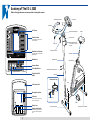
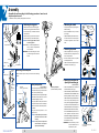
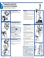
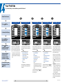
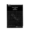
Cateye ergociser
OPERATING INSTRUCTIONS
EC-L32OO
®
CONTENTS
Introduction
For safety operation
----------------------------------------------------------------------------------- 3
Anatomy of the EC-L3200
Assembly
------------------------------------------------------------------------ 2
----------------------------------------------------------------------------------------------------- 4
Mounting the control unit / How to use the pulse sensor
------------------------------- 6
Your first ride ----------------------------------------------------------------------------------------------Operation of buttons & workload shift lever
Input your data
----------------------------------------- 10
------------------------------------------------------------------------------------------- 12
Start the exercise
---------------------------------------------------------------------------------------- 14
Purpose of exercise / Exercise program / Glossary of terms
Trouble shooting / Warranty service
Specifications
---------------- 16
------------------------------------------------------- 18
Package
(If anything is missing, contact the dealer where you purchased this unit.)
9
r
6
7
3
8
2
e
w
q
y
u
1
8
t
i
0
o
5
4
1
2
3
4
5
6
7
8
9
0
q
w
e
r
t
y
u
i
o
Main Body
Handlebar Post
Seat Post
Rear Leg Pipe
Front Leg Pipe
Handlebar
Handlebar Clamp Bracket
Quick Release Lever
Saddle
Pedals (L & R)
Sensor Clip
Pulse Sensor
Control Unit
Batteries (AA x 4)
Mounting Screw (2 large
screw, 2 small screw, 2
Belleville Spring)
Spanner Wrenches
Hexagon Wrench
Operating Instructions (this
book)
Warranty Card
Anatomy of The EC-L3200
Refer to this page whenever necessary while reviewing this manual.
Control Unit
Handlebar Clamp Bracket
Handlebar
LCD Screen
EC-L3200
LOADING LEVEL
Control Unit Mounting Base
MODE
Saddle
PULSE
1
PULSE
2
3
CADENCE
4
SPEED
5
TIME
6
DISTANCE
7
Data Description
Cable Connector
Indicates what the figure in each
column stands for
Workload Adjustment Dial
Sensor Clip
Pedal resistance is adjusted
in 8 grades
WORK RATE
8
CALORIE
Workload Level Indicator
INSTRUCTIONS
1. Attach pulse sensor to earlobe.
2. Press
button to turn screen on.
3. Press
button to enter "AGE".
4. Press
buttons to adjust to your age.
5. Repeat 3 & 4 to set other exercise conditions.
6. Press
button and start pedaling.
7. Adjust pedal resistance with workload
adjustment dial.
Quick Release Lever
Shows the position of the workload
adjustment dial
Seat Post
Mode Button
Handlebar Post
EC-L3200
Seat Post Knob
Advance Button
TARGET PULSE
ON / OFF
VALUE
ADJUST
MODE
ADVANCE
Value Adjust Button
Handlebar Post Fastening Screw
Target Pulse On/Off
Button
Base Post
Pulse Sensor Plug
Crank
Pulse Sensor Jack
Cable Clip
Plug
Mounting Screw Hole
Cable Inlet
Cable connector from the main
body is connected here.
Earlobe Sensor
Pedal
Battery Case
PUSH
OPEN
Distance Scale Switch
Accessible when the battery case
is removed. Select either km or
mile.
2
Front Leg with Casters
Rear Leg with level adjusters
Introduction
Thank you very much for your purchase of Cat eye Ergociser Model EC-L3200. The model EC-L3200 is
a new high-tech exerciser with a built-in computer designed to allow aerobic exercise conveniently for
the purpose of advancing your cardiovascular system, and maintaining and improving physical
endurance.
You can do aerobic exercise effectively when your pulse rate meets constantly a target pulse rate that
is decided under your age, physical strength and purpose.
Read this manual carefully to achieve maximum fitness from your EC-L3200 and keep it handy.
Symbol marks used for safety precautions in this manual
The descriptions with the following symbol marks in this manual refer to very important matter in terms
of your safety and handling of the unit. You are strictly requested to observe these precautions.
WARNING
Should this indication be neglected and improper handling attempted by the operator, such critical risks which could result in a fatal or serious injuries are
impending.
CAUTION
Should this indication be neglected and improper handling attempted by the operator, there are possibilities of physical injuries or material damages.
REFERENCE This symbol mark describes advantageous items to the user or complementary items.
For safety operation
Please read through this section before proceeding to operate your Cat eye Ergociser.
For your safety, you are kindly requested to observe the following:
CAUTION
WARNING!!!
• Before using the EC-L3200, it is important to consult a medical specialist if you
are suffering from any of the following:
heart disease (angina pectoris, myocardial infraction), hypertension, diabetes,
respiratory disease (asthma, chronic
bronchitis, pulmonary emphysema, etc.),
articular metamorphosis, rheumatism,
gout, or any other disease and physical
complaints.
• If you are not used to regular physical activities, it may be dangerous to suddenly
start strenuous exercise. Try to increase
your exercise level gradually and always
avoid careless exertion.
• If you feel sick or sense something is
wrong with your body during exercise,
immediately stop exercising.
• In case children, sick persons, or those
who are physically disabled are using
this unit, be sure that they should be attended by someone else.
• The pulse (earlobe) sensor should always be used with the correct
age setting. This allows the upper pulse limit alarm to issue a
warning when your heart rate has unusually increased.
• Be sure to remove pulse sensor cord by holding the plug instead
of pulling it by holding the cord.
• Do not use this unit in areas where there are a lot of spray products or inflammable substance.
• Do not use this unit with the ventilation hole, etc. covered.
• Do not let substance fall or insert into the openings of the unit.
As otherwise, it may result in failures of the unit.
• Do not disassemble the main unit or the control unit. Consult the
dealer you purchased the unit from, in case of trouble.
• Avoid using or storing the unit outdoors or in areas where it is
exposed to direct sunlight.
• Do not use the unit in areas where temperature and humidity are
high.
• Avoid using the unit in other manners than stated in this manual.
• Do not use the unit whenever it does not operate normally, it is
dropped or damaged, or when it is wet. When such events have
occurred, contact our authorized dealer in your location.
• Do not wipe the unit with organic solvents such as thinner, kerosene, gasoline or alcohol. Wipe it clean with a cloth with neutral
cleanser, and wipe with a dry cloth.
• Wipe off the sweat drops on the main unit and control unit, after use.
• For repairing the unit, be sure to use the genuine parts for Cateye
Ergocisers only.
3
EC-L32OO
Assembly
Assemble the unit according to the following procedure. Learn how to
adjust each part as well.
* In addition to the tools provided, please prepare a screw driver.
1
Fig. 1
Front
TOP mark
Pipe with casters
1. Attaching the leg pipes
4. Mounting the saddle
• Remove the two screws from each leg pipe.
• Place the front leg pipe under the front end of
the main body as Fig. 1 and fasten it with the
screws securely.
• Place the rear leg pipe under the rear end of
the main body as Fig. 2 and fasten it equally.
CAUTION: Place the leg pipes with the "TOP"
mark facing upward.
ADJUSTMENT: Turn the level adjusters if necessary, in order to compensate the
floor unevenness.
REFERENCE: When the marking line is at the
top, the rear leg is at the same level
as front.
• Lift up the seat post to a proper height for
saddle mounting.
• Mount the saddle at the top of the seat
post as Fig. 5.
• Adjust the saddle angle to make it horizontal, and use the #13 end of the spanner
wrenches to tighten the nuts from both
sides.
5. Attaching the pedals
• Attach the pedals to the crank as Fig. 6
and fasten them firmly using the #15 end
of the wrench provided.
• Be sure to identify R and L of the pedal
with the engraved mark.
• Fasten clockwise the R pedal, and counterclockwise the L pedal. (Fig. 7)
Marking line
8
6 4 2
Level adjusters
1
3
5
7
Rear
Belleville
spring
2
5
#15 Wrench
Crank
Fig. 6
Front
Right(R)
2. Mounting the handle post
Fig. 7
6. Mounting the handlebar and
adjusting the handlebar grip
Base post
Handlebar
post
fastening
screw
Seat post
Left(L)
• Attach handlebar post to base post and secure with fastening
screws.
Handlebar post
Nut
#13 Wrench
Fig. 5
Rear leg pipe
Fig. 2
4
3. Seat post position
3
Seat post
Pitch 1" (approx. 25 mm)
Seat post knob
Loosen
Pull
Fig. 3
Fig. 4
4
(ADJUSTMENT)
• Turn the seat post knob clockwise and counterclockwise and pulling it allows the seat
post to slide up and down.(Fig.4)
• Adjust the seat post to an appropriate height
and release the seat post knob, and move
the seat post slightly up or down.
• The spring inside the seat post knob drives
the pin into the nearest hole on the seat post
and turn it clockwise until the seat post cannot wobble.
• The pitch of the seat post hole is 1 inch
(approx.25mm).
CAUTION: Confirm that the pin of the seat
post knob must be in the hole
securely.
CAUTION: Do not pull the seat post knob
while mounted. The seat post
may drop down suddenly.
6
Handlebar clamp bracket
Quick release lever
(ADJUSTMENT)
Assembly completed.
(Control Unit already mounted)
• Place the Handlebar clamp bracket and
the handle bar into place. (fig 8)
• Place both washers provided onto the Quick
release and screw it into the handlebar clamp
assembly until there is a loose fit. The Quick
release works like a clamp, test it to determine
when it is open (clamp assembly will be
loose). Test for proper tightness using the lever action to close the Quick Release. If at
this time the handle bar is too loose open the
Quick Release lever and turn the screw portion into the Handlebar clamp bracket 1 to 2
turns. Repeat the Test process until the
handle bar is held tightly into place when the
lever is closed and loose enough to adjust the
bar when the lever is open.
REFERENCE: Be sure that when you close
the Quick Release lever it
snaps firmly into place.
5
Washers
1
Fig. 8
2
Tighten
Handleber
Tighten
(Lay down)
Loosen (Raise)
Turn the quick relaese lever
for adjustment
EC-L32OO
Mounting The Control Unit
How to Use The Pulse Sensor
Complete the following procedure before riding
1
Push-Open
P
O US
P H
E
N
1. Setting the distance scale
4. Adjustment
• Remove the battery case from the control unit (Fig. 1)
• Set the distance scale switch to "km" or "mile" at your choice.
(Fig. 2)
• Adjust the position of each part in such a way that your riding posture
will be as illustrated. (Fig. 6)
• The saddle height should be at the level where your knee is slightly
bent when the pedal is at the lowest position. (Refer to Item 3 of
Page 4 on how to adjust)
• Using the quick release lever, determine the handlebar angle where
you can keep a natural posture. (Item 6 of Page 5)
• When moving the unit, lift up the rear of the unit holding the rear end
of the saddle, and roll forward on the casters of the front leg.
Fig. 1
MILE
KM
Battery case
Distance scale switch
4
Fig. 2
2. Loading (replacing) the batteries
2
Insert
• Put the batteries provided [AA(R6) x 4] in the battery case, making sure that the polarity is correct (Fig. 3) and insert the battery
case into the control unit.
• Execute the "All Clear" process as shown below.
How to do "All Clear"
AA(R6) Batteries
• Press the three buttons
simultaneously, and
holding them down press the
button.
• All the LCD segments appear at a time, then the screen
turns blank. (Refer to page 10)
Battery case
Fig. 3
EC-L3200
Trainingspuls
Ein / Aus
Einstellung
Modus
Replacing the batteries
Start / Stop
• When the batteries wear out, mark appears on the screen. If it
appears replace the batteries soonest possible.
• Alkaline batteries are recommended because of longer life.
CAUTION: Be sure to execute the "All Clear" upon replacing
the batteries, too.
All clear process
Fig. 6
5. Attaching the pulse sensor
• Insert the pulse sensor plug into the sensor jack at the back of the
control unit. (Fig. 7)
• Use the sensor clip to take up slack in the cable, to keep the cable
from swinging too much during exercise. (Fig. 7)
• Keep the pulse (earlobe) sensor attached on the sensor clip when
not in use. (Fig. 8)
6. How to use the pulse (earlobe) sensor
• Clip the pulse sensor at the center of your earlobe of either side.
(Fig. 9) Ear rings or other ornaments must be removed while using
the pulse sensor.
• Attach the cable clip to the collar of your clothes during the exercise,
to prevent excessive swinging of the sensor cable. (Fig. 10)
Recommended exercise posture
5
Sensor clip
Sensor jack
Fig. 7
Pulse sensor plug
Sensor clip
Earlobe sensor
Cautions on handling the pulse sensor
3
3. Mounting the control unit
Cable Inlet
Cable
connector
• Insert the cable connector of the 7P cable coming out of the
main body, securely into the cable inlet at the back of the control
unit. (Fig.4).
• Place the control unit on the mounting the base as Fig.5, and
fasten the 2 screws securely.
Fig. 4
When the pulse rate display seems to be incorrect, check the
pulse sensor as described below.
* Remove the pulse sensor from your earlobe and close it with
nothing in between, while the screen is in working state.
•
mark lights up and pulse rate is displayed as 0 --- Normal
•
mark lights up intermittently when you swing the cable --The cable is half broken
•
mark doesn't light up --- The cable is broken
•
mark lights up even when the pulse sensor is attached to
your earlobe or some object --- The cable is short-circuited.
Fixing screw
Fig. 5
• When it is cold, massage your earlobe before use, to improve blood
circulation.
• Try not to change the position of the pulse sensor during the exercise.
• If the
symbol frequently lights up during the use, remove the earlobe sensor once and reattach.
• The sensor cable can be broken if pulled strongly. Treat it with sufficient care.
Control unit mounting base
6
7
Cable clip
Fig. 8
6
Earlobe sensor
Fig. 9
Fig. 10
Cable clip
EC-L32OO
Your First Ride
Try a ride so that you can familiarize yourself with the unit.
Attach Pulse Sensor
No-Display Screen
Press
Initial Display Screen
In-Exercise Display (A) Screen
In-Exercise Display (B) Screen
No-Display Screen
Button
EC-L3200
LOADING LEVEL
EC-L3200
MODE
PULSE
1
MODE
PULSE
1
PLL
PULSE
2
Confirm Initial Display
CADENCE
3
4
SPEED
4
5
TIME
5
6
DISTANCE
6
7
WORK RATE
8
CALORIE
Press
Button
Begin Exercise
Press
Button
Confirm In-Exercise
Display(A) and (B)
Turn the workload
adjustment dial.
Confirm the Pedal
Resistance changes.
MODE
ADVANCE
When power is off, no display appears on
the screen. In this state, the battery consumes minimal power. When the unit is
not in use, turn off to "No-Display" state.
• If input signal is not entered into the
control unit in 10 minutes, the unit is automatically turned off to "No-Display"
state.
Finish Exercise when
Buzzer beeps. Press
Button
MODE
PULSE
1
TPL
7
AGE
CADENCE
3
SPEED
4
TIME
5
DISTANCE
6
min
sec
WORK RATE
8
CALORIE
VALUE
ADJUST
MODE
ADVANCE
MODE
PULSE
1
rpm
min
sec
7
CADENCE
3
SPEED
4
TIME
5
DISTANCE
6
WORK RATE
watt
8
CALORIE
VALUE
ADJUST
MODE
ADVANCE
PU
PU
mile/h
mile
7
CADENCE
3
CAD
SPEED
4
SP
TIME
5
DISTANCE
6
WORK RATE
8
kcal
CALORIE
T
DIST
7
WOR
8
CAL
EC-L3200
TARGET PULSE
ON / OFF
VALUE
ADJUST
MODE
ADVANCE
In the "No-Display" state, this "Initial Display" appears with a press of the Advance
button
.
After the "Initial Display" state, this "In-Exercise Display (A)" appears with a press of
the advance button
.
The In-Exercise Display (A) and (B) alternately appear with each press of the mode
button
.
Preset Initial Display (from top)
• Upper-Limit Pulse Rate
160 bpm (beats per minute)
• Target Pulse Rate
120 bpm (beats per minute)
• Target Exercise Time
15 minutes
• Age
40 years old
Exercise Display (A) Screen (from top)
• Current Pulse Rate
(bpm)
• Pedal Cadence
(rpm-revolutions per minute)
• Countdown Timer
(minute:second)
• Work Rate
(watt)
Change pedal resistance by moving
the workload adjustment dial to the
left for easier and to the right for
harder.
In-Exercise Display (B) Screen (from top)
• Current pulse Rate
(bpm)
• Simulated Current Speed
(mile/h or km/h)
• Simulated Trip Distance
(mile or km)
• Calorie Consumption
(kcal)
The above display can be modified to your
personal data, but at this stage leave them
as they are.
MOD
1
2
EC-L3200
TARGET PULSE
ON / OFF
LOADING LEVEL
PULSE
2
EC-L3200
TARGET PULSE
ON / OFF
EC-L3200
LOADING LEVEL
PULSE
2
EC-L3200
VALUE
ADJUST
EC-L3200
LOADING LEVEL
PULSE
2
3
TARGET PULSE
ON / OFF
EC-L3200
LOADING LEVEL
If you press the Advance button
when
the screen is in this state, it turns to the
"No-Display" state.
If you press the advance button
when
the screen is in this state, it turns to the
"No-Display" state.
EC-L320
TARGET PULSE
ON / OFF
VALUE
ADJUST
MODE
ADVANCE
When the target time has elapsed,
the buzzer will beep to notify the
target has been achieved. After the
target time has been achieved, the
timer will start counting up.
Slow down your pace gradually,
and finish your exercise. Review
your workout data shown on the
screen, and press the Advance
button
. The screen will go off
and the power will be disconnected.
REFERENCE: If you wish to continue your exercise after hearing
the beep to notify you the
achievement of the target time,
you can continue the exercise.
The calorie consumption will be
continuously logged.
Now, we believe you have understood what you can expect from
the exercise of Cateye Ergociser
EC-L3200.
8
9
EC-L32OO
Operation of Buttons & Workload
Adjustment Dial
To make the most of the functions of the unit.
1. Functions of the buttons
2. Workload Adjustment Dial and Work rate
Advance Button
Advance Button
It makes the program proceed. Each time you press this button, the display advances in the order as Fig. 1.
NO-DISPLAY
Mode Button
It is used in two ways.
a) In the "Initial Display", each press of this button switches the item to be modified in the order as Fig. 2.
b) In the "In-Exercise Display", each press of this button converts the screen alternately as Fig. 3.
INITIAL DISPLAY
Fig.1
IN-EXERCISE DISPLAY A/B
Before starting exercise, set the
workload adjustment dial to the following standard level in accordance
with your age and sex.
Age
Male
Female
20~30's
3
2
40~50's
2
1
Over 60
1
1
Easier
• Work rate (watt) is determined by the position of the workload adjustment dial, and your
pedal cadence. (Fig.5)
• To get the desired work rate during the exercise, first adjust it roughly by the workload
adjustment dial, then precisely by changing your pedal cadence. The workload can be
shifted to 8 positions, 1 is the easiest and 8 is the heaviest.(Fig.4) Turning the workload
adjustment dial leftward make the workload easier and turning it the rightward make the
workload heavier. Each position of the workload adjustment dial is identified by the
mark displayed on the screen. The following table shows work rate (watt) corresponding
to each workload adjustment dial position, and the pedal cadence.
Harder
Work Rate (watt)
Pedal Cadence
Shifting Position
1
2
3
4
5
6
7
8
Value Adjust Buttons
In the "Initial Display", each button serves to change the blinking numerical value in
each selected mode.
Button ------------------ Each press increases the numerical value by 1, and
when held down, it increases rapidly.
Button ------------------ Each press decreases the numerical value by 1, and
when held down it decreases rapidly.
Mode Button
AGE
TARGET EXERCISE TIME
Target Pulse On/Off Button
The
mark turns on and off each time you press this button.
When the
mark is shown, the buzzer beeps if your pulse rate deviates from the
target pulse rate zone. When the
mark is off, such a function is not activated.
[Beeping Sound Pattern]
0
1
2 (sec.)
Beyond the target pulse rate zone
2kHz
Below the target pulse rate zone
1kHz
• The buzzer function is not activated until your pulse rate once reaches the target
pulse rate.
• The target pulse rate zone may slightly differ depending on the target pulse rate
that you input, but approximately within +/- 5 bpm from the target pulse rate.
TARGET PULSE RATE
UPPER-LIMIT PULSE RATE
Fig.5
IN-EXERCISE DISPLAY (A)
When new batteries are loaded, or when abnormal signal is received due to electrostatic trouble, etc., the screen may show abnormal displays. In such a case, first
hold down the set buttons
and the mode button
simultaneously, then
press the advance button
. The screen first turns to "No-Display" state, then it
displays all the readings for 2 seconds. Finally it returns to the "No-Display" state.
Recovery Function
If you press the advance button
by mistake during exercise, making the
screen turn to "No-Display" state, press any of the other buttons, except the advance button
, within 10 seconds. The screen recalls the previous "In-Exercise
Display" state.
PLL
• Press the three buttons
simultaneously, and holding
them down press the
button.
• Be sure to perform this procedure
after replacing the batteries.
TPL
rpm
mile/h
km/h
min
sec
mile
km
EC-L3200
Trainingspuls
Ein / Aus
Einstellung
Modus
In the "No-Display", if you hold down the mode button
and press the advance
button
, the data that was set for your last exercise can be recalled. This function is useful when you can use the unit exclusively and want to repeat the same
exercise program.
*This function becomes effective 10 seconds after the unit is turned off.
10
1
2
3
4
5
6
4
7
AGE
watt
kcal
Fig.4
120
25
50
75
100
125
150
175
200
33
65
100
135
165
200
235
265
41
85
130
170
215
255
295
335
50
105
155
210
260
310
355
405
65
140
215
285
350
420
480
545
85
195
265
355
440
520
595
680
2 Pulse Sensor "OK" Mark
Indicates that the pulse sensor functions properly.
3 "Error" Mark
Appears when the pulse rate jumps up or down abnormally, or when the
pulse sensor is not attached to your earlobe properly.
4 Data Mark
Indicates the mode in display.
PLL ---------- Upper-Limit Pulse Rate
TPL --------- Target Pulse Rate
AGE --------- Age of the user
5 Pulse Mark
Flickers synchronized with the pulse
4
7
8
Fig.6
100
6 Target Pulse Rate On/Off Mark
Start / Stop
Memory Function
80
Indicates the position of the workload adjustment dial.
IN-EXERCISE DISPLAY (B)
All-clear Process
70
1 Workload Level Indicator
Screen Display
"All Clear" Function
60
REFERENCE: At the middle position of each workload level on the workload adjustment dial, it shows the exact work rate as per above figure.
CAUTION:
Do not overtighten workload adjustment dial.
Fig.2
Fig.3
Special functions of buttons
50
When this mark is on, the buzzer functions to signal when your pulse rate is
out of the target pulse rate zone.
7 Unit Mark
Indicates the unit of the display figure.
8 Battery Alarm Mark
Indicates that the battery power has exhausted.
11
EC-L32OO
Input Your Data
The target pulse rate calculated from your age is the key of effective
exercise.
Adjusting Saddle Height
LOADING LEVEL
1
Adjust the saddle height to get correct exercise posture.
MODE
PULSE
PLL
PULSE
TPL
CADENCE
2
3
SPEED
4
5
Adjusting Handlebar Angle
Buttons to use and display progress
Attaching Pulse Sensor
Attach the pulse sensor to your earlobe correctly.
Press Advance Button
to turn on the
Input Your Age
Use
and
buttons to input your age.
Input Target Exercise Time
Use
time.
and
buttons to input exercise
7
AGE
8
MODE
PULSE
PLL
PULSE
TPL
CADENCE
2
3
SPEED
4
5
min
sec
Use
and
pulse rate.
TIME
DISTANCE
6
7
AGE
8
WORK RATE
1
MODE
PULSE
PLL
PULSE
TPL
CADENCE
2
3
5
min
sec
TIME
DISTANCE
6
7
AGE
8
3
WORK RATE
CALORIE
MODE
PULSE
PLL
PULSE
TPL
CADENCE
SPEED
4
5
min
sec
TIME
DISTANCE
6
7
AGE
8
1) Press the mode button
, to make the numerical value "15:00" in
the third column flicker, which is the preset standard exercise time.
2) Input the desired exercise time, using the
or
button.
Setting range: 0 ~ 99 minutes, in 1 minute increment
SPEED
4
2
12
1) Press the mode button
, and the numerical value "40" at the
bottom flickers, which is the preset standard age.
2) Input your age, using the
or
button.
* Each time the age is modified, the upper-limit pulse rate (PLL) and
the target pulse rate are automatically set, based on "200 – age"
and "160 – age" respectively.
3. Input Target Exercise Time
LOADING LEVEL
1
buttons to input target
2. Input Your Age
CALORIE
LOADING LEVEL
Input Target Pulse Rate
WORK RATE
CALORIE
LOADING LEVEL
1
TIME
1) After setting the correct saddle height and handlebar angle, ride on
the saddle and attach the pulse sensor to your earlobe.
to turn on the "Initial Display". You
2) Press the Advance button
can modify the "Age", "Exercise Time" and "Target Pulse Rate"
from this display, as described below.
DISTANCE
6
Adjust handlebar angle to get correct exercise posture.
Press the advance button
Initial Display.
min
sec
1. Press Advance Button
WORK RATE
CALORIE
4. Input Target Pulse Rate
1) Press the mode button
to make the numerical value "120" in the
second column flicker, which is the preset standard target pulse rate.
2) Input the desired target pulse rate, using the
or
button.
Setting range: 80 ~ (Upper Pulse Limit – 10) bpm
For a person who has built up enough physical strength:
The target pulse rate cannot be set higher than (Upper Pulse
Limit – 10). If you wish to set a higher target pulse rate, first
modify the Upper Pulse Limit upward. The maximum settable
Upper Pulse Limit is 199, so you can set the target pulse rate to
189 bpm at maximum.
• How to modify the upper-limit pulse rate
1) Press the mode button
until the upper-limit pulse rate
(value in the top column) flickers.
2) Input the desired upper-limit pulse rate using the
or
button.
• In general, modification of the upper-limit pulse rate is not always recommended because the target pulse rate automatically set at [180 – age] is adequate for effective exercise.
13
EC-L32OO
Start The Exercise
Continuing exercise with the EC-L3200 will make you fit.
Adjust the workload level
LOADING LEVEL
1
Set the workload adjustment dial at an appropriate position, in accordance with your
age and sex.
MODE
PULSE
PLL
PULSE
TPL
CADENCE
2
3
Press Advance Button
(Start to Exercise)
Buttons to use and display progress
, start
You can read various data using the mode
button
.
Finish Exercise when Buzzer
Beeps
When the target exercise time is over, the
buzzer signals the end. (The timer starts to
count-up after this point.)
Review Your Data
to review the
to turn off the
TIME
DISTANCE
7
Press Mode Button, Review (A)
& (B) Screens
Press the mode button
data, and record them.
Press the advance button
screen to No-Display state.
min
sec
6
Upon pressing the advance button
pedaling.
AGE
8
WORK RATE
LOADING LEVEL
MODE
PULSE
1
PULSE
2
3
rpm
SPEED
4
5
min
sec
TIME
DISTANCE
6
7
8
CADENCE
WORK RATE
watt
LOADING LEVEL
CALORIE
40~50's
Over 60
2
1
1
1
PULSE
2
CADENCE
3
4
mile/h
SPEED
mile
DISTANCE
5
6
TIME
7
8
PULSE
CADENCE
mile/h
SPEED
mile
DISTANCE
TIME
7
8
With each press of the mode button
during exercise, the In-Exercise Display (A) and (B) alternate. (Refer to page 9) You can read
different data while you exercise.
CALORIE
MODE
5
6
7. Alternate Display
WORK RATE
kcal
3
4
1) After setting the data, press the advance button
and start pedaling. The timer starts to countdown, so the remaining time is shown.
2) Keep pedaling in the range of 50~70 rpm, increasing the workload
level by one point per minute, so that your pulse rate comes close
to the target pulse rate smoothly.
3) After your pulse rate once reaches the target pulse rate, the buzzer
will beep if your pulse rate is out of the target pulse rate zone. In such
a case, adjust your pedal cadence upward or downward by about 5
rpm so that your pulse rate can stay within the target pulse rate zone.
* In case you cannot get back to the target pulse rate zone by only
changing the pedal cadence, adjust the workload adjustment dial
to change the workload level upward or downward.
PULSE
PULSE
14
Female
2
MODE
1
2
When the upper-limit pulse rate is exceeded
Beyond the target pulse rate zone
Below the target pulse rate zone
When the target exercise time has elapsed
Male
3
6. Start to Exercise
1
If the buzzer beeps continuously to signal that your pulse rate has exceeded
the upper-limit pulse rate, stop exercising immediately.
Beeping sound pattern
0
1
2(sec.)
Age
20~30's
CALORIE
LOADING LEVEL
WARNING !!!
Set the workload adjustment dial at an appropriate position, in accordance with your age and sex.
SPEED
4
5
5. Adjust Workload Level
WORK RATE
kcal
CALORIE
8. Finish Exercise
1) When the buzzer beeps to signal the end of the target exercise
time, finish exercise. Recall the In-Exercise (B) screen, by pressing
the mode button
.
2) Review the consumed calories (kcal) and the simulated trip distance (mile or km).
* You may continue exercise even after the buzzer beeps to signal
the end, if you have not reached to your target of consumed calories. The timer starts counting up after this point.
3) Press the advance button
to turn off the screen to the "NoDisplay" state.
15
EC-L32OO
Purpose of Exercise / Exercise Program
Glossary of Terms
To maximize the benefit of your exercise.
1. Purpose of Exercise
PULSE RATE (bpm)
Do you often get out of your breath when you go up stairs or walk fast? This is because
your ability to take oxygen into your body is getting weak. Such ability is evaluated by a
value called MOU (Maximum Oxygen Uptake), which represents the maximum amount
of oxygen taken into your body per 1 kg of body-weight in a minute (ml/kg.min.). The
MOU value can be used as a scale of your physical endurance.
The average MOU value is 40-50 ml/kg.min. for men in their twenties, and 30-40 ml/
kg.min. for women of the same age. In general, the MOU value becomes less as you
get older, and the more you lack proper exercise, the faster it decreases. It is said the
MOU value less than 22 ml/kg.min. may result in illness of cardiovascular system, and
in restriction of your daily life.
Continued aerobic exercise several times per week maintains and improves your MOU
value, activating oxygen supply to your cardiovascular system. With the EC-L3200,
you can perform aerobic exercise effectively and efficiently.
200
mp
ulse
limi
t (2
20-
180
When you exercise, your heart rate continues to increase as the exercise level becomes more intense, but there is a certain limit. This limit is called the maximum
heart rate. The maximum heart rate decreases as you become older. The decrement ratio in the maximum heart rate differs individually, depending on whether one
is physically well trained or not. In general, the maximum heart rate decreases yearly
by 0.6-1.0 beats per minute.
Age
)
Max
imum
puls
e lim
it x 8
160
5%
140
120
er p
um p
Maxim
ulse
limit
x 70%
Exercise Time for Each Session
A minimum of 30 minutes exercise is necessary for each session of exercise. A 5
minute warm up period, and 20 minutes of exercise time, with a 5 minute cool down
period, is suggested as a standard exercise. For weight reducing exercise, over 30
minutes exercise time at the low level of the target pulse rate is recommended with a
5 minute cool down.
How many days a week for exercise
Minimum two exercise days a week is required just to maintain your present fitness
level. With 3-4 exercise days you can expect improvement. Always consult with your
doctor before proceeding with any exercise program.
ulse
TAR
RGET ZONE
um pu
lse lim
get
Pu
lse
it x 60
%
limi
t (2
00-
Age
(19
0-
Tar
(180
Rat
eA
How to decide your target pulse rate
When you input your age, the EC-L3200 automatically sets your target pulse rate at
[160 – age]. This target pulse rate corresponds to 50-60 % of the exercise level for the
twenties, 40-50 % for the sixties. (Refer to "Exercise Level" on page 17.) The older you
are, at the less intense level your target pulse rate is set because of such programming
of the EC-L3200. The exercise level automatically set by this unit could be too hard
even for a young person, if he is a beginner. If you feel it too hard, you may decrease
the target pulse rate by 10 bpm from the original level. If you feel too easy, you may
increase it by 10 bpm so that you can continue exercise in the appropriate target zone
as illustrated. If you can continue your exercise at the target pulse rate of [180 – age],
your exercise can be considered as effective enough. Upgrade your exercise gradually so that you can reach the suggested final target of [190 – age].
The heart rate is the number of heart beats per minute measured by a cardiograph.
However, we can measure the pulse by touching the arteries near the skin, such as
carotid arteries; which is called the pulse rate.
Upp
Maxim
100
uto
mat
ical
ly S
)
Age
)
- Ag
e)
et (
160
–Ag
30
40
50
60
At the earlobe, blood flow fluctuates with each beat of the heart, and the optical
permeability through the earlobe changes every time the heart beats. The EC-L3200
measures the pulse rate with the sensor, amplifying the changes of optical permeability. An earlobe is a suitable part for sensing the pulse rate during the physical
exercise since its muscular movement during exercise is very little and doesn't affect
the pulse rate detection.
The heart rate and the pulse rate differ from each other in principle and method, but
their value per minute is equal, and therefore both can be interpreted as synonymous.
Upper-Limit Pulse Rate (PLL)
e)
90
20
3. Glossary of Terms
Maximum Heart Rate
imu
2. Exercise Program
Aerobic exercise will be more effective when it is continued at a certain pulse rate, which is
determined based on your age and physical strength. This is called "Target Pulse Rate".
Max
Target Pulse rate Chart
70
Age
The maximum pulse rate is related with the age, and is calculated by standard formulas such as [220 – age] or [204 – 0.69 x age]. In the EC-L3200, it is calculated as [200
– age] and called the upper-limit pulse rate (PLL), which is lower than the standard
formula of the maximum pulse rate and gives you a safer upper-limit pulse rate. When
your pulse rate exceeds the preset upper-limit pulse rate, a buzzer beeps to warn you.
You can adjust the upper-limit pulse rate according to your physical condition.
Target Pulse Rate (TPL)
A pulse rate to be maintained during the exercise is called the target pulse rate
(TPL). When your pulse rate is more than 5 bpm over or under the target pulse rate
which you set before the exercise, a buzzer beeps to signal you.
Exercise Level
Since the pulse rate gets higher according to the intensity of exercise, the exercise
level can be indicated by how high your pulse rate is compared with your pulse rate
at rest. It is shown by percentage as follows:
Exercise Level (%) =
Pulse Rate in exercise – Pulse Rate at rest
x 100
Maximum Heart Rate – Pulse Rate at rest
Therefore, the target pulse rate for a certain exercise level can be obtained through
the following formula:
Target Pulse rate = (Maximum Heart Rate – Pulse Rate at rest)
x
Caution:
Exercise Level (%)
+ Pulse Rate at rest
100
Concentrated and repeated exercise in a day may produce an adverse result.
16
17
EC-L32OO
Trouble Shooting / Warranty Service
Specifications
Trouble Shooting
Trouble
No display appears
or abnormal display
appears on the
LCD panel.
Buzzer beeps continuously.
"Distance Scale
Unit" display is
wrong.
The pulse rate
reading is not displayed.
The target pulse
rate alarm does not
beep.
Check Item
Press the advance button
and
check if the display appears or not.
Proceed "All-clear Process", and
press the advance button
and
check if the display appears or not.
[Page 10 (Fig. 4)]
Check if your upper-limit pulse rate
(PLL) has been set correctly. [Page
13-2]
Check if the distance scale unit was
set correctly according to instructions. [Page 5-7]
Check if the sensor plug is inserted
properly. [Page 7-5]
Check if the pulse sensor is correctly attached to your earlobe.
[Page 7-6]
Check if the plug or the cable of the
pulse sensor is damaged. [Page 7]
Has your pulse rate once reached
the target pulse rate? [Page 10]
Is the Target Pulse On/Off mark
lit on the screen? [Page 10]
Suggested Remedy
If still no display appears, the batteries are
dead. Replace all four
batteries. [Page 10 ]
Input your age correctly.
The upper-limit pulse
rate is set at [200 – age].
Follow instructions on
page 6-1 to set the desired distance unit.
Insert the sensor plug
properly, and attach the
pulse sensor correctly.
ITEM
Load
SPECIFICATIONS
Eddy current system utilizing permanent magnet
Load Range
Manual Adjustment
1 ~ 8 level
Cadence
50 ~ 120 rpm
Load Range
25 ~ 680 watts
Acceleration
2-step belt drive
Control System
4-bit micro-computer
Display Function
Function
Range
Accuracy
Pulse Rate
50 ~ 220 bpm
± 1 bpm (stable state)
Cadence
20 ~ 240 rpm
± 1 rpm
Exercise Time
00 min. 00 sec. ~ 99 min. 59 sec. ± 0.003 %
Alarm Function
Work Rate
0 ~ 999 watts
± 5 watts (at 50 watts)
Speed
0 ~ 99 miles/h (km/h)
Simulated value
Distance
0.00 ~ 99.99 miles (km)
Simulated value
Calorie
0 ~ 999 kcal
Estimated value
Target Pulse Rate Alarm
Signals if the pulse rate deviates from target pulse rate zone
Upper-limit Pulse Rate Alarm
Signals when pulse rate exceeds preset upper-limit pulse rate
In case of damage on
the pulse sensor, replace it with a new one.
The target pulse rate
alarm is activated only
after your pulse rate
reaches the target.
Press the Target Pulse
On/Off button
to
turn on the
mark.
Exercise Time Alarm
Signals when preset target exercise time is reached
Power Supply
AA (R6) x 4 (Battery life: Approx. 200 hours by alkaline battery)
User's Weight Limit
286 lbs (130 kg)
Measurement
Handlebar Height:
Weight
39-7/32 ~ 52-7/16 inches (996 ~ 1332 mm)
Saddle Height:
33-9/32 ~ 46-31/32 inches (845 ~ 1193 mm)
Length:
42-11/32 inches (1075 mm)
Width:
19-11/16 inches (500 mm)
Net Weight:
55.5 lbs. approx. (27 kgs)
* Specifications and design are subject to change without notice.
U.S. Pat. 4929825 / Design Pat. Pending
Warranty Service
• Cat Eye Co., Ltd. guarantees that the Cateye Ergociser™ Model EC-L3200 is free
from material defects and malfunctions under correct and normal use for a period
specified in the separate Warranty Card. In case there should be defects or malfunctions, Cat Eye will repair or replace the unit or parts, according to the terms and
conditions mentioned in the Warranty Card.
• If repair service is required, contact your dealer where the unit was purchased.
• The warranty covers only the main unit and the control unit. Accessories such as the
pulse sensor are not covered.
18
Copyright© 2000
Cat eye Co., Ltd.
Printed in Japan
ECMeL32-000118-1
19
®
CO.,LTD.
2-8-25, Kuwazu, Higashi Sumiyoshi-ku, OSAKA, 546-0041 JAPAN
PHONE: 81-6-6719-7781
FAX:
81-6-6719-2362
066660001 (E)