1
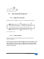
JetBox 8210 User Manual Hardware www.korenix.com Copyright Notice Copyright© 2007 Korenix Technology Co., Ltd. All rights reserved. Reproduction without permission is prohibited. Information provided in this manual is intended to be accurate and reliable. However, the original manufacturer assumes no responsibility for its use, or for any infringements upon the rights of third parties that may result from its use. The material in this document is for product information only and is subject to change without notice. While reasonable efforts have been made in the preparation of this document to assure its accuracy, Korenix assumes no liabilities resulting from errors or omissions in this document, or from the use of the information contained herein. Korenix reserves the right to make changes in the product design without notice to its users. Acknowledgments Korenix is a registered trademark of Korenix Technology Co., Ltd. All other trademarks or registered marks in the manual belong to their respective manufacturers. 2 Overview | Korenix Table of Content Copyright Notice ............................................................................................ 2 Acknowledgments .......................................................................................... 2 Table of Content ............................................................................................................. 3 Chapter 1 Overview ................................................................................................ 5 Chapter 2 Hardware Specification .......................................................................... 5 Chapter 3 Hardware Feature .................................................................................. 6 3‐1 Dimensions ............................................................................................. 6 3‐2 Front Panel IO Connectors ..................................................................... 7 3‐2‐1 Power ON/OFF Switch .................................................................... 7 3‐2‐2 COM Connectors ............................................................................ 8 3‐2‐3 Power LED Indicator ....................................................................... 9 3‐2‐4 CF LED Indicator ............................................................................. 9 3‐2‐5 Ethernet Connector ........................................................................ 9 3‐2‐6 Audio Connector .......................................................................... 10 3‐2‐7 Compact Flash Socket .................................................................. 10 3‐3 Rear Panel IO Connectors .................................................................... 11 3‐3‐1 Digital IO Connector ..................................................................... 11 3‐3‐2 VGA Connector ............................................................................. 11 3‐3‐3 Ethernet Connector (the same as 3‐2‐5) ..................................... 12 3‐3‐4 Reset Button ................................................................................. 12 3‐3‐5 USB1 ~ USB4 Connectors ............................................................. 12 3‐3‐6 Power Connector ......................................................................... 13 3‐4 Memory and Storage ........................................................................... 13 3‐4‐1 Overview ...................................................................................... 13 3‐4‐2 Boot Memory ............................................................................... 14 3‐4‐3 Compact Flash Card ..................................................................... 14 3‐4‐4 SDRAM ......................................................................................... 14 3‐4‐5 Battery Backup SRAM (NVRAM)—Optional ................................. 14 3‐4‐6 I2C EEPROM ................................................................................. 15 3‐4‐7 Security EEPROM ......................................................................... 15 3‐5 RS232/422/485 Serial Ports ................................................................. 15 3‐5‐1 Overview ...................................................................................... 15 3‐5‐2 Configuration ............................................................................... 15 3‐6 Digital Input and Output ...................................................................... 16 3‐6‐1 Digital Input .................................................................................. 16 Korenix | Overview 3 3‐6‐2 Digital Output ............................................................................... 17 3‐7 Hardware Unique Serial Number ......................................................... 17 Chapter 4 Appendix .............................................................................................. 18 4‐1 Chart Index ........................................................................................... 18 4‐2 Customer Service ................................................................................. 19 4 Overview | Korenix Chapter 1 Overview The advantage of adopting Korenix JetBox series is ready-to-use. Korenix is devoted to improve the usability of embedded computer in industrial domain. Besides operating system (Linux/WinCE), Korenix provides device drivers, protocol stacks, system utilities, supporting services and daemons in one Compact Flash card to make system integration simple. Further, Korenix provides application development toolkits for users to build up their own applications easily. JetBox 8210 is a high performance, compact and rugged embedded computer. All-in-one device with small volume, fanless design and a capability to withstand a wide range of temperatures is suitable for industrial severe environment. It is equipped with Intel Xscale PXA270 RISC processor and 128MB SDRAM (256MB optional) and supports Linux and WinCE5.0 to meet requirements of industrial PC applications. For better expansibility, it carries 4 USB ports, 2 RS-232 ports and 2 RS-232/422/485 ports for versatile peripheral and interfaces and one Compact Flash slot for system integration. It also supports VGA (640*480) and audio to give users much flexibility in industrial applications. In addition, it is equipped with 2 RJ-45 ports and supports daemons and web server to accommodate to the network communication environment today. With complete software solution and excellent hardware design, JetBox series is the best choice of embedded computer. Chapter 2 Hardware Specification Model JetBox 8210 CPU Intel Xscale PXA270 32 bits 416 MHz SDRAM 128MB (default), 256 MB (optional) Boot Memory 256 KB Flash (Boot loader), up to 1024 KB Compact Flash Interface 1 slot (OS and Applications) VGA 640*480*16‐bits Audio AC97 stereo audio output with 2.1 W amp, Korenix | Overview 5 Model JetBox 8210 mono MIC input Ethernet 10/100 Base‐T * 2 NVRAM Battery backup SRAM 1 MB (optional) EEPROM (I2C) 128‐256 Bytes USB Host USB v1.1 Host Port * 4 RTC Battery backup external RTC WDT External Watch Dog Timer UART 16C550 compatible RS232 * 2, RS232/422/485 * 2 DIO Buffered TTL DI *16, DO * 16 Battery 3V Li‐Battery EEPROM (Security) 128 bytes EEPROM Unique Number 6 bytes unique serial number Reset Button 1 Power Switch 1 LED Indicator Power * 1, CF * 1 Dip Switch (In Box) 8‐bits Dip‐Switch * 4 (Configuration) USB Slave (In Box) 1 Power Input 10VDC‐48VDC, (‐48VDC) or 100VAC‐240VAC@50‐60 Hz Power Consumption 5W Dimensions 250(W)*66.5(H)*106.3(D)mm Operating Temperature ‐15℃ ~ 70℃, 5 to 95% RH Net Weight 1.07kg Chart 1 JetBox 8210 HW spec Chapter 3 Hardware Feature 31 Dimensions The following figures show the dimensions of JetBox 8210. The following sections give you detailed information about the function of each I/O connector. 6 Hardware Feature | Korenix Chart 2 JetBox 8210 appearance Chart 3 JetBox 8210 ME drawing 32 Front Panel IO Connectors 321 Power ON/OFF Switch This switch is used to turn the system power on and off. Korenix | Hardware Feature 7 Charrt 4 Power switch 322 COM M Conne ectors COM M 1 and CO OM2 Connecctors The JetBox 821 10 provides 2 D‐sub 9‐p pin connecttors for RS‐2 232/422/48 85 com mmunication ns. The defaault setting of COM1~ C COM2 is RSS‐232. Please refer with h the programmiing guide fo or changing the settings or use thee “SerCon” ccontrol app plet of th he control p panel to chaange the settings. COM M3 and COM M4 Connecctors The JetBox 821 10 provides 2 D‐sub 9‐p pin connecttors (COM3 and COM4)) for RS‐232 2 com mmunication n. Notte the settin ngs are storred in the EEPROM, no ot registry. IIt’s necessaary to configgure each hardware e target manually or prrogrammattically. Replacing the C CF card with h OS and d hive registtry data will not affectt the mode settings of the COM ports. Charrt 5 COM conn nector R RS-232 RS-422 R RS-485 (2-wirre) (44-wire) 1 DCD T X D-(A) DATA A-(A) T X D-(A) 2 R X D T X D+(B) DATA+ +(B) T X D+(B) 3 T X D R X D+(B) R X D+(B) 4 DTR R X D-(A) R X D-(A) 5 GND GND 8 Hardwaare Feature | Korenix RS-485 GND D GND RS-232 RS-422 6 DSR RTS-(A) 7 RTS RTS+(B) 8 CTS CTS+(B) 9 RI CTS-(A) RS-485 RS-485 (2-wire) (4-wire) Chart 6 COM connector PIN assignment 323 Power LED Indicator This LED indicator is used to indicate the power on off status. 324 CF LED Indicator This LED indicator is used to indicate the CF card access status. 325 Ethernet Connector A standard RJ‐45 jack socket with LED indicators shows its Active/Link status (Green LED) and Speed status (Orange LED). Chart 7 Ethernet connector Pin 10/100 BaseT Signal Name 1 TX+ 2 TX- 3 RX+ 4 Korenix | Hardware Feature 9 Pin 10/100 BaseT Signal Name 5 6 RX- 7 8 Chart 8 Ethernet connector PIN assignment 326 Audio Connector JetBox 8210 provides an AC97 stereo audio output with a 2.1 W amplifier and a mono MIC input. Chart 9 Audio connector Pin Audio Signal Name 1 OUT_R+ 2 OUT_R‐ 3 OUT_L+ 4 OUT_L‐ 5 MIC_IN 6 GND Chart 10 Audio connector PIN assignment 327 Compact Flash Socket This socket is used by the Compact Flash (CF) card contains OS and the user’s applications. 10 Hardware Feature | Korenix Charrt 11 Compactt flash socket 33 Rear P Panel IO O Conne ectors 331 Digiital IO Connecto or JetB Box 8210 prrovides 16 d digital input channels and 16 digitaal output ch hannels. Charrt 12 Digital IO O connector 332 VGA A Connecctor JetB Box 8210 su upports VGA A (640*480)) output to ggive users m much flexibiility in indu ustrial appliications. ency of JetB Box 8210 VG GA output iss around 62 2 Hertz, nott the Notte: Because the freque general VGA 60 0 or 75 Hertz. Therefore, the VGA A output of the JetBox 8210 is NO OT fullyy compliantt with all th he VGA mon nitors, espe ecially for so ome monito ors withoutt “Auto Sync” functionality. Korenix | Hardware Feature 11 1 Charrt 13 VGA connector Pin VGA Signal S Name 1 R RED 2 GREEN 3 B BLUE 4 5 G GND 6 G GND 7 G GND 8 G GND 9 10 G GND 11 12 13 H‐‐SYNC 14 V‐‐SYNC 15 Charrt 14 VGA connector PIN assignment 333 Ethe ernet Co onnector (the sa ame as 3 325) 334 Rese et Butto on Thiss button is u used to reseet the CPU ccausing the system reb boot. 335 USB B1 ~ USB B4 Conne ectors JetB Box 8210 prrovides 4 USSB type “A” female connectors for USB periph herals. 12 Hardwaare Feature | Korenix Charrt 15 USB conn nector Pin USSB Signal N Name 1 VC CC 2 DA ATA‐ 3 DA ATA+ 4 GND Charrt 16 USB conn nector PIN asssignment 336 Pow wer Conn nector JetB Box 8210 co omes with a Phoenix co onnector that carries a 7 ~ 40 VDC C external pow wer input. Charrt 17 Power co onnector Pin Power Signal S Name 1 V VCC 2 G GND Charrt 18 Power co onnector PIN assignment 34 Memorry and Storag ge 341 Overrview ory architeccture of JetB Box 8210. The gray block The following ffigure shows the memo meaans it is reseerved as sysstem usage.. Korenix | Hardware Feature 13 3 JetBox 8210 Boot Memory SDRAM SRAM (256 KB) (128 – 256 MB) (1 MB) Boot Loader OS Image, Object Store, Applications Application Run Time Data I2C EEPROM Security EEPROM Li Battery (64 Bytes) (64 Bytes) Application Application Security CF Card Default Settings Settings (16 MB – 50 MB) (64 Bytes) (64 Bytes) System Default Settings System Security Settings User’s applications File OS Image File, Hive Registry File Chart 19 JetBox 8210 memory architecture 342 Boot Memory There is 256 KB of Flash ROM for the Boot Loader program. 343 Compact Flash Card One type‐II Compact Flash card interface is designed for store Windows CE image and user’s applications. 344 SDRAM JetBox 8210 supports 128 MB of SDRAM. The Windows CE Image occupies 16 MB to 50 MB depending on the model. The remainder 112 MB to 78 MB is arranged for Windows CE Object Store and applications. 345 Battery Backup SRAM (NVRAM)—Optional 1 MB of battery backed SRAM to provide a security way to save the important run 14 Hardware Feature | Korenix time information and avoids the risk of power fails. 346 I2C EEPROM 128 Bytes I2C type EEPROM is provided for the default settings. There is 64 bytes is reserved for system usage, and 64 Bytes is provides for user’s applications. 347 Security EEPROM 128 Bytes security EEPROM is provided for the security settings usage. It’s can’t be read/write by the hardware programmer, only the software interface can. There is 64 bytes is reserved for system usage, and 64 Bytes is provides for user’s applications. 35 RS232/422/485 Serial Ports 351 Overview JetBox 8210 supports four serial ports. The first 2 ports, COM1 and COM2, are RS232/422/485 configurable. The later 2 ports are dedicated for RS232 mode. Refer with 3‐3‐2 VGA Connector for connector pin assignments. 1 352 Configuration JetBox 8210 configures COM1 and COM2 as RS232 operation mode as factory default settings. These operation mode settings are stored in the system EEPROM, not registry, and the settings are applied during system boot up. One configuring utility named “SerCon” located in the control panel could be used to change the settings and save to the system EEPROM. Replace the CF card “B” of JetBox 8210 “B” with from a well configured CF card “A” of JetBox 8210 “A” will not change the serial port configurations of JetBox 8210 “B”. It’s suggested to configure the serial ports programmatically if a great quantity of JetBox 8210 is applied. Refer with SW Manual if software programming interface is necessary for configuring Korenix | Hardware Feature 15 programmatically. 36 Digital Input and Output 361 Digital Input JetBox 8210 supports 16 digital input channels. Refer with 3‐3‐1 Digital IO Connector for connector pin assignments. Below figures show 2 ways to use digital input function. Chart 20 Dry connect for digital input Chart 21 Wet connect for digital input 16 Hardware Feature | Korenix 362 Digital Output JetBox 8210 supports 16 digital output channels. Refer with 3‐3‐1 Digital IO Connector for connector pin assignments. Below figure show how to use digital output function. 1 Chart 22 Wet connect for digital output 37 Hardware Unique Serial Number JetBox 8210 provides a 6 bytes hardware unique serial number for identification. User’s applications can utilize this ID for security protection. In addition, the drivers for security are implemented as a non‐unloadable driver and the related registry settings are set as hive boot (non‐changeable). Korenix | Hardware Feature 17 Chapter 4 Appendix 41 Chart Index Chart 1 JetBox 8210 HW spec ........................................................................ 6 Chart 2 JetBox 8210 appearance ................................................................... 7 Chart 3 JetBox 8210 ME drawing ................................................................... 7 Chart 4 Power switch ..................................................................................... 8 Chart 5 COM connector ................................................................................. 8 Chart 6 COM connector PIN assignment ....................................................... 9 Chart 7 Ethernet connector ........................................................................... 9 Chart 8 Ethernet connector PIN assignment ............................................... 10 Chart 9 Audio connector .............................................................................. 10 Chart 10 Audio connector PIN assignment .................................................. 10 Chart 11 Compact flash socket .................................................................... 11 Chart 12 Digital IO connector ....................................................................... 11 Chart 13 VGA connector .............................................................................. 12 Chart 14 VGA connector PIN assignment .................................................... 12 Chart 15 USB connector ............................................................................... 13 Chart 16 USB connector PIN assignment ..................................................... 13 Chart 17 Power connector ........................................................................... 13 Chart 18 Power connector PIN assignment ................................................. 13 Chart 19 JetBox 8210 memory architecture ................................................ 14 Chart 20 Dry connect for digital input ......................................................... 16 Chart 21 Wet connect for digital input ........................................................ 16 Chart 22 Wet connect for digital output ...................................................... 17 18 Appendix | Korenix 42 Customer Service Korenix Technologies Co., Ltd. 9F, No. 100‐1, Ming‐Chuan Rd., Shing Tien City, Taipei, Taiwan Tel:+886‐2‐82193000 Fax:+886‐2‐82193300 Business service: [email protected] Customer service: [email protected] Korenix | Appendix 19 00.080.02 20 Appendix | Korenix