1
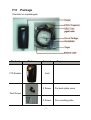
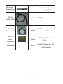
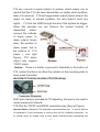
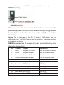
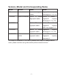
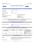
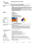
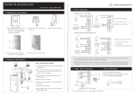
Fingerprint Reader
F10
User Guide
F10 description
Pass/Fail Indicator & Button
The indicator glow green which the
flash interval is 1sec, in normal ready working state, and constantly
glow green for 3 sec as the identification is positive, if the
authentication fail it will constantly glow red light for 3 sec. When the
sliding ID card or Mifare Card to be verified is valid, the indicator
displays rapidly green flash it interval time is 1 sec., you can press
the button to start the reader while it in normal working state, and
wait for 3 sec., switch the reader into idle state.
Fingerprint Sensor Enroll or match fingerprint
Power Indicator It constantly glow green in the normal supply or
idle state!
DB15 Port, mainly apply to connect the access controller and build
network for communication
RJ45 Prot"which mainly apply to adjust while it connect to PC
-1-
F10 Package
Checklist on unpackaged#
Product
F10 Reader
Picture
Amount
Purpose
1unit
2 Screw
Fix back plate cover
4 Screw
Fix mounting plate
Fast Screw
-2-
Use for Turning screw
between reader and
mounting plate
Pin-in-hex
Screwdriver
1
15Core
pigtail cable
1 piece
Ethernet
Comm. cable
1 piece
TCP/IP connect assistant
comm. Prot
RS232
comm.
connector
1 piece
RS232 Adjust comm.
Prot !
Manual etc
1 set of
Contain Manuel and CD
with software
-3-
DB15 pin
Installation
-4-
Connect to the access controller
As a fingerprint reader, F10 isn’t able to work alone , only after be
linked the access controller, it offer a fingerprint identification front
-end for system, provide the controller with a standard or self-define
Wiegand signal, such as other Proxy Card Reader
adopt the
standard signal (D0,D1,GND) connection method.(see standard
connection illustration)
Notice #Whatever the power of F10 supply by the access controller,
or doesn’t it, the two equipment’s GND must be in common
connection, to ensure transfer the wiegand signal steady.
Create Network Configuration
The only way to create network is to adopt RS 485 for F10,( see
standard connection illustration), we recommend to use the standard
RVVP2 $ 1.0 shield twisted-pair and RS-232/RS-485 converter
which own power supply, if there are more than 32 unit in one
network, please utilize RS 485 HUB to connect .
F10 power
F 10 is powered by 12 VDC, which the idle current is 50mA, and the
working current is about 400mA, as well as F10 offer a
12VDC/300mA power output which apply to meet the external
reader supply (see standard connection Illustration)
Notice: F10 is powered not only by the access controller, but also can depend
on external power
External Reader
F10 utilize the function of wiegand input to support a external
reader, at the same time F10 connect external reader via standard
way, and the pin of reader (D0,D1,12V ) according to the pin of
F10( Wiegand In D0"Wiegand In D1"GND"12VOUT) one by one
to connect(see standard connection Illustration)
Special Notice: when there is a Mifare module in the F10, the Wiegand input is
invalid, if there is no external reader; don’t need to do this connection.
Connect to Alarm
-5-
F10 can connect a signal (alarm) to system, which mainly use to
remind that the F10 has been dismantled ,no matter what condition,
when it is removed F10 will trigger alarm output (brown wire) in the
power on state, in normal condition, the wire doesn’t send any
signal., F10 will link GND through the wire if the system be trigger,
follow this principle we can achieve the remind function of
dismantled
alarm,
connect the cathode
of alarm power to
alarm output( brown
wire), the positive of
alarm power link to
the positive of F10
power ( see right
Figure), F10 alarm
output only support
12VDC alarm.
Notice: There is a button to prevent to dismantle in the bottom of
F10, realize function is to utilize the cylinder on the mounting plate to
keep press the button
Assistant Communication Port Hookup
RJ45 port mainly is provided for PC adjusting, this port is not used to
create equipment network.
F10 offer the TCP/IP and RS232 connection way (See up Figure)
Special Notice: Because F10 assistant communication port is on the bottom
of equipment, it isn’t necessary to remove the unit for creating connection , so
in normal used, no matter how it must setup communication password( the
-6-
communication pass word of F10 is setup by self in the software ) .
DB15 Hookup
F10 are connected to the access controller, the external reader, the
power supply and to create RS485 network through the pig-tail wire
bundle that protrudes from the rear of the unit (See connection
illustration).
Notice: The all black wire in the DB 15 bundle is GND, which does not
differentiate type. The RS232 may be used in the future. This communications
is invalids at exit factory
DB15 Connector is a 15 core pig-tail cable, which defined by color,
like as the follow chart
Pin
Colour
Signal
Connect to
1
Green
Wiegand Out Data 0
D0 of the access controller
2
Yellow
Wiegand In Data 0
D0 of the external reader
3
Green/white Wiegand Out Data 1
D1 of the access controller
4
Yellow/whiteWiegand In Data 1
D1 of the external reader
5
Brown
Alarm Output
Alarm output
6
Black
Wiegand GND
Wiegand GND
7
Blue/white RS-485 (+)
RS-485 (+)
8
Blue
RS-485 (-)
RS-485 (-)
9
Violet
RS-232 TX
RS-232 Rx
10
Violet/white RS-232 Rx
RS-232 TX
11
Black
Signal GND
Signal GND
-7-
12
Black
Power GND
12V power input (GND)
13
Red
Power 12V IN
12V power input (positive)
14
Red /white 12V OUT
12V Output%positive&
15
Black
12V Output%GND&
GND
Installation Notice Item
This product is designed for indoor installation, if it
has to be installed it outdoor, please place the
equipment in proper surroundings, you must
beware of not exposing it to water or harsh
condition, we remind to cover up the cable into the
wall, if it isn’t capable to do, you must obtain the
user’s permission before to install.
Locate a comfortable height for finger place, firstly
use the screwdriver along with the unit to turn off
the screw in the bottom of the unit, and take away
mounting-plate, there are four fix-hole in the
mounting-plate (see right illustration a, b, c, d),
keep secure it on the wall using supplied screw, and fix the F10
reader body on the mounting-plate. Please strictly complied with the
wire definition and color, after finish the hookup, cut the expose part
of the unwanted wire, especially red/white wire, and use the
insulating tape to wrap it, because the red/white wire provide a
output 12VDC voltage, when there is no external reader, No mater
what, you must cut this wire and wrap it to keep away short circuit,
You must ensure that hookup is correct follow the above table
before power up and use.
-8-
Version, Model and Corresponding Name
Model
Version
Name
F10
Standard
Standard
Name
fingerprint Fingerprint
reader
F10-ID600
Build-in ID module Build-in
capacity
600,support 1:1 or 1:N
ID
moduleBuild-in ID module "
fingerprint reader
Fingerprint
capacity
600,support 1:1 or 1:N
F10-ID5000
Build-in
ID
moduleBuild-in ID module '
fingerprint reader
Fingerprint
capacity
5000, only support 1:1.
F10-ID8000
Build-in
ID
moduleFingerprint
fingerprint reader
F10-SMART
Build-in
module
MifareBuild-in
IC
capacity
600,support 1:1 or 1:N
moduleBuild-in Mifare module"
fingerprint reader
Fingerprint
capacity
immensity 6
The shape or parameter of the above products are subject to charge without
notice, please read this user guide carefully before mounte and use.
-9-